6. 3D Scanning and printing
Our Homework this week:
Our assignment this week is to:
Group assignment:
- Test the design rules for your 3D printer(s)

- Document your work and explain what are the limits of your printer(s) (in a group or individually)
- Document your work to the group work page and reflect on your individual page what you learned
Individual assignment:
- Design and 3D print an object (small, few cm3, limited by printer time) that could not be easily made subtractively
- 3D scan an object, try to prepare it for printing (and optionally print it)
Learning outcomes
- Identify the advantages and limitations of 3D printing
- Apply design methods and production processes to show your understanding of 3D printing.
- Demonstrate how scanning technology can be used to digitize object(s)
Have you answered these questions?
- Linked to the group assignment page
- Explained what you learned from testing the 3D printers
- Documented how you designed and made your object and explained why it could not be easily made subtractively
- Documented how you scanned and prepared an object (for 3D printing)
- Included your original design files for 3D printing (both CAD and common format for 3D printing)
- Included your hero shots
Schedule
- Wednesday: find and watch 3D printing tutorials
- Thursday: begin printing test files (group project), research design process (individual project)
- Friday: work on 3D modeling design; also work ahead on updating parametric design for machining week
- Saturday: 3D scanning, 3D printing design file, learning about / working on machining, getting help with bootloader
- Sunday: clean up documentation
- Monday: focus on preparing for teaching my own class
- Tuesday: bootloader work, finish cleaning up and uploading documentation
Some 3D Printing Resources
- Here is a video on changing the filament on your Ender Pro 3.
- Here is a bed leveling tutorial. It seems a bit more intensive than what I’ve seen before.
- Here and here are some other tutorials about levelling the bed.
- Here is a useful resource shared during the week for failed prints.
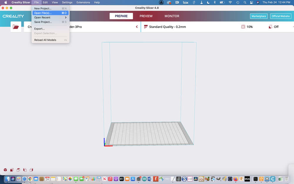
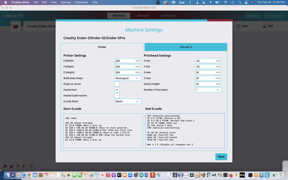
- I downloaded and installed Creality Slicer Software
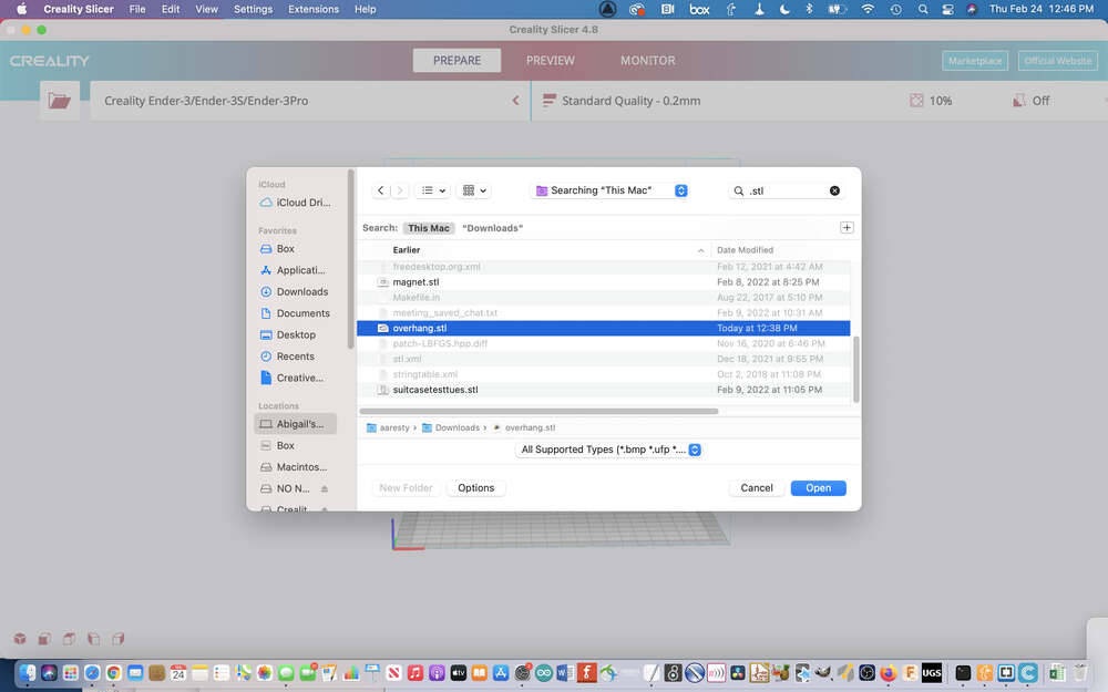
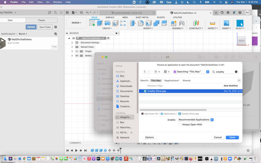
- I followed this tutorial to work on going from Neil’s STL files to a print.
3D Printing Process
There are several discrete phases of additive manufacturing. These include:
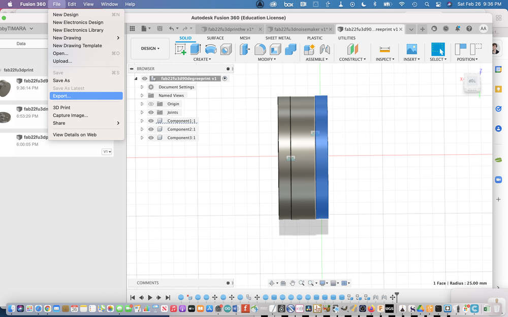
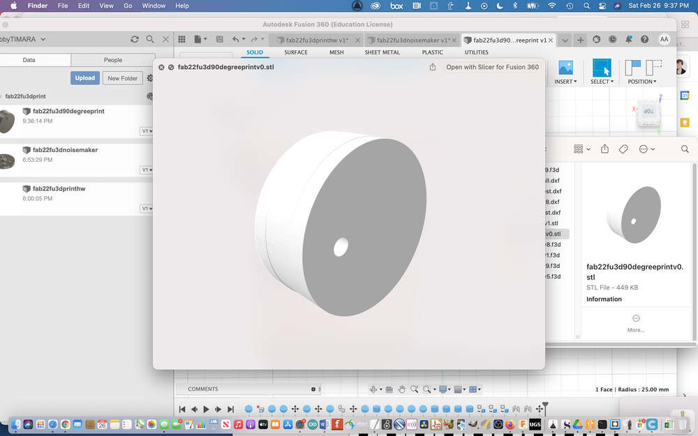
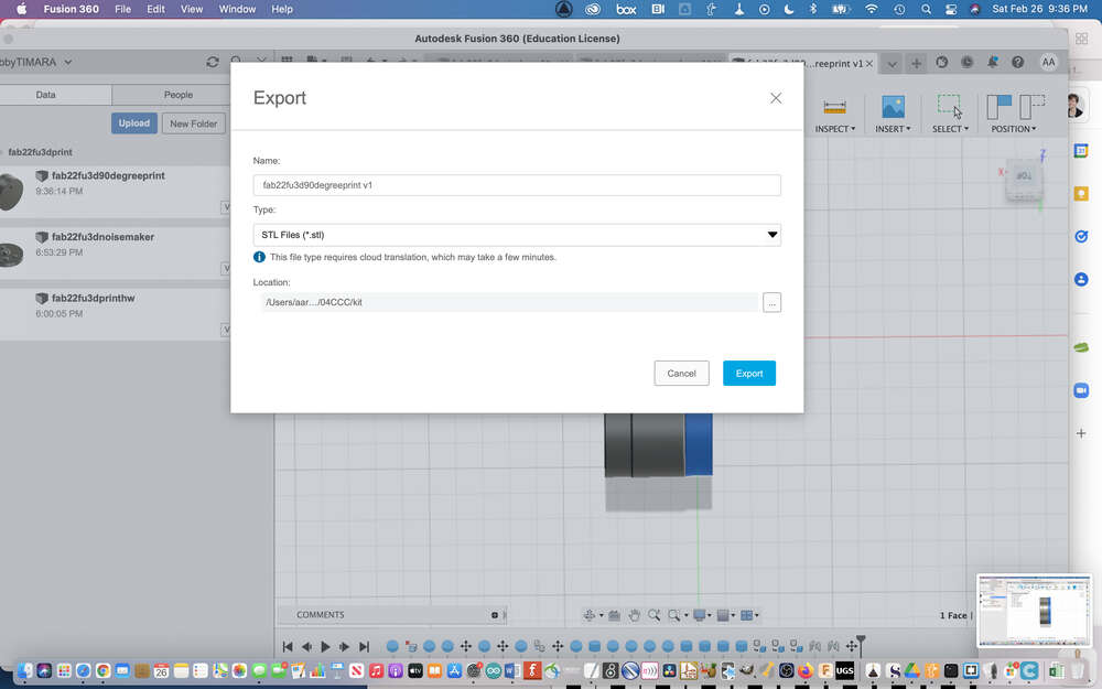
- Desigining an object for printing. Keep in mind general additive manufacturing design constraints as well as constraints specific to your machine; at the end of this process, you will export an .stl file that you can use for the next phase of the process: slicing!
- Slicing your object involves using specialized software that converts a 3D model that you want to print into G-Code that your machine will understand.
- The last step in the 3D printing process is preparing your machine for printing and printing your object.
Depending on your goals and resources, you can mix and match these steps. For example, you can find .stl files for free on sites like Thingiverse. Alternatively, you could create your own design using CAD software like Fusion 360 and send it out for printing to a local or online company. If you are printing an object yourself, whether you make your own design or download an object from Thingiverse, you will still need to use a slicer to generate the GCode for your machine. This allows you to adapt the print to the requirements of your specific machine.
Below, I will go through each of the steps in the 3D printing process in order.
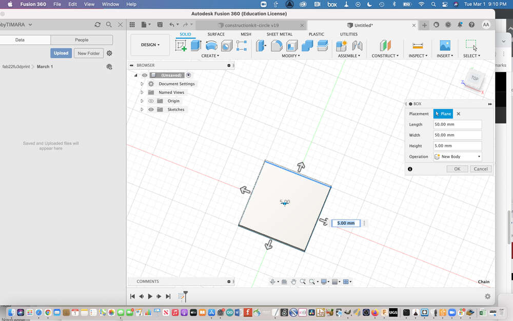
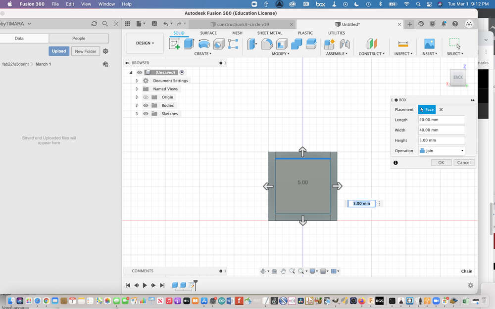
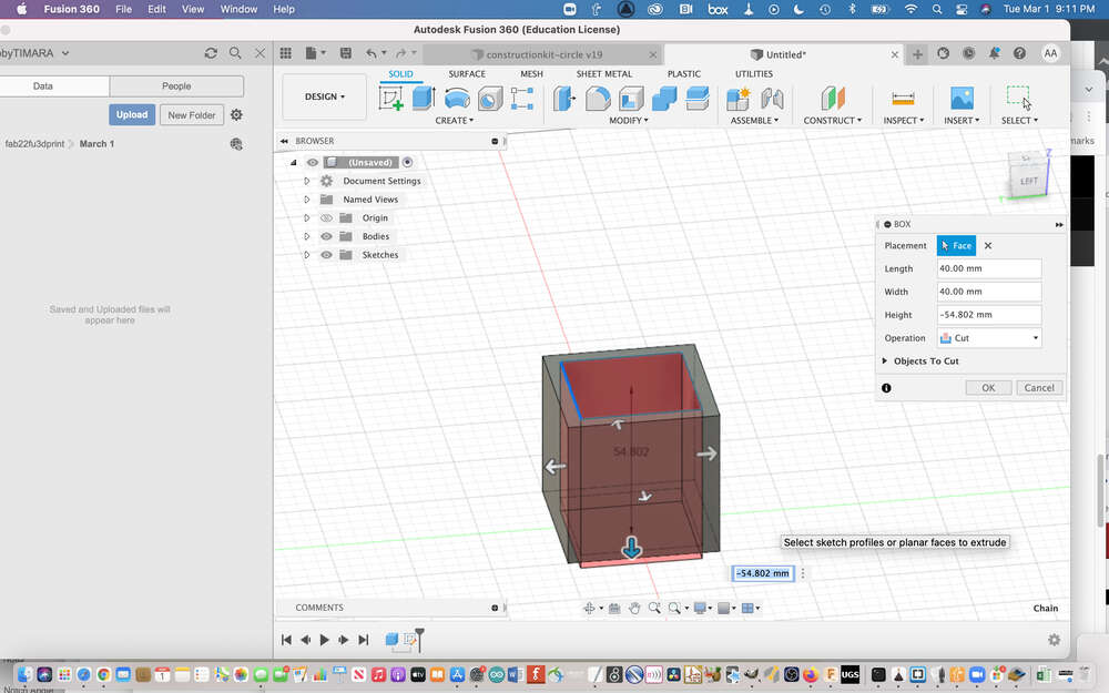
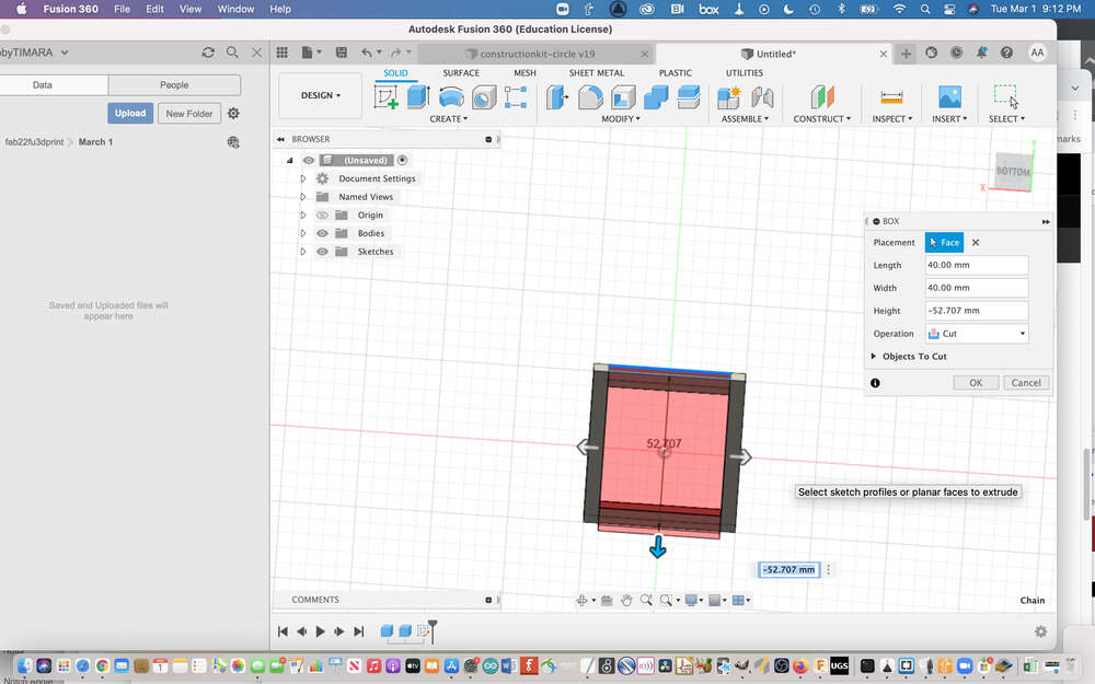
Designing an Object

I really struggled with what to make for this assignment, and had several different failures, one after the other. With each failure, however, I learned something new.
Originally, I thought I would try to make a spool-like object, in order to make some progress towards my final project. The spool would have been for winding magnet wire to make speakers.
You can see the photos of this process here:
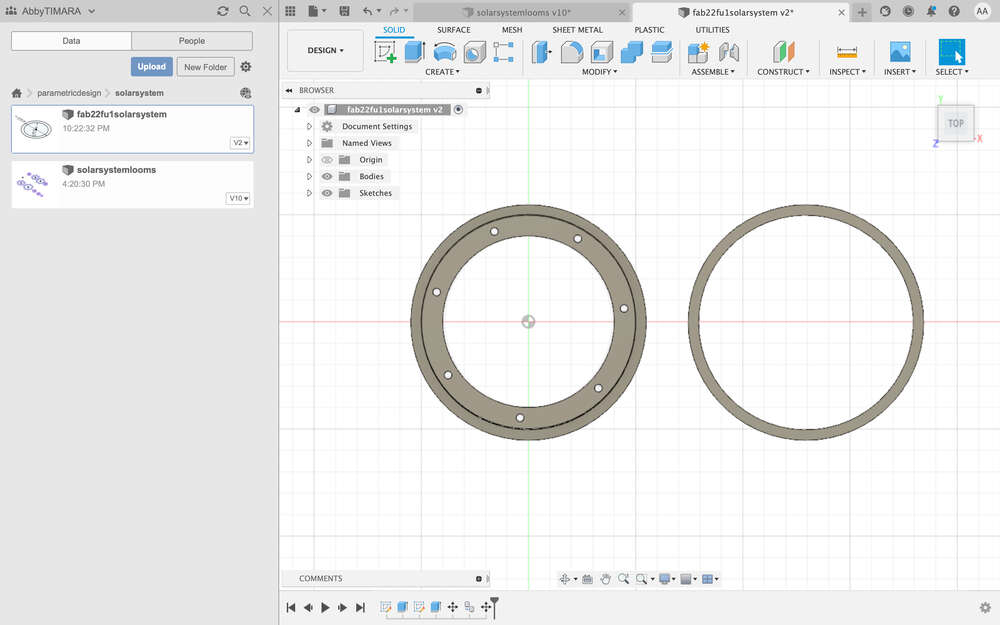
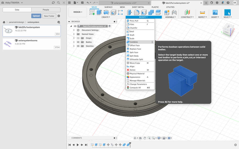
However, when I showed this design to my teacher, they said it would be actually very easy to create subtractively with a mill and/or a lathe and would therefore not meet the requirements of the assignment.
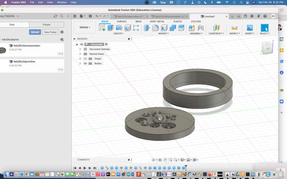
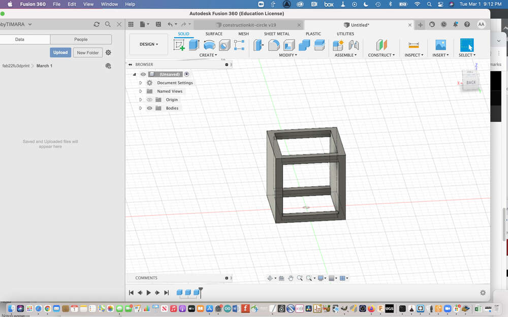
Next, I spent some time experimenting somewhat randomly in Fusion 360 and trying to refresh my memory about how to use the software. I was just letting the software guide my work. As I experimented with spheres and cylinders, I started to think about the textures that I was creating, and had the idea to create a noisemaker with a hole in which you can place objects to move and shake inside the 3D printed object. The inner textures of the printed object would impact the movement of the inserted objects and the sounds they would make.
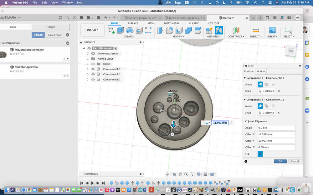
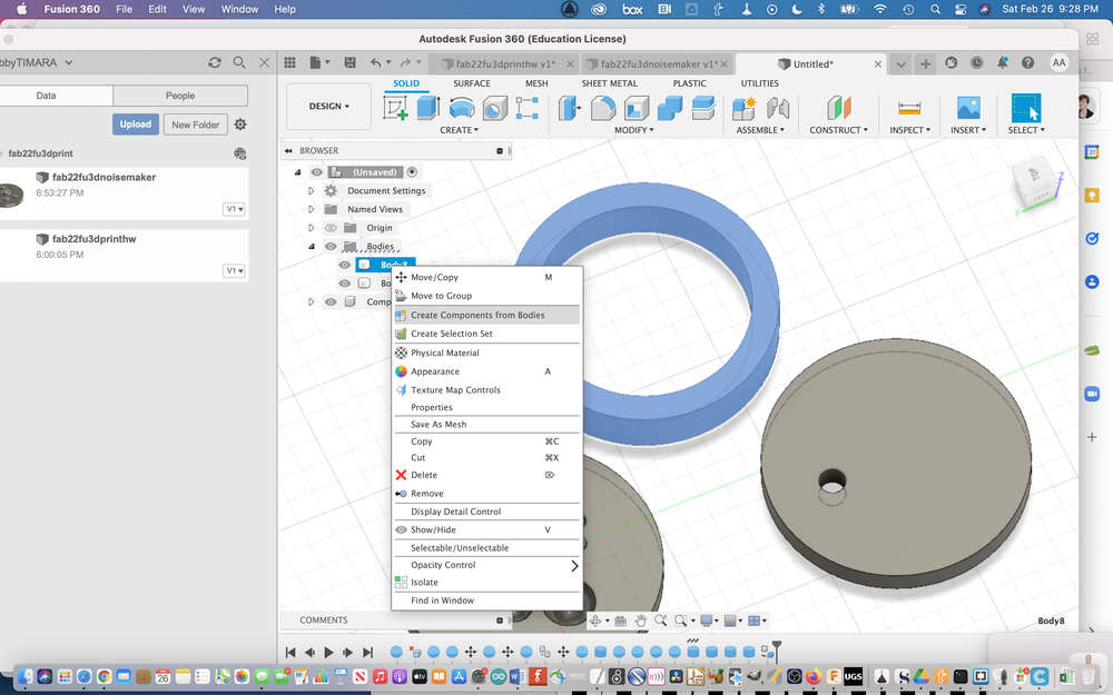
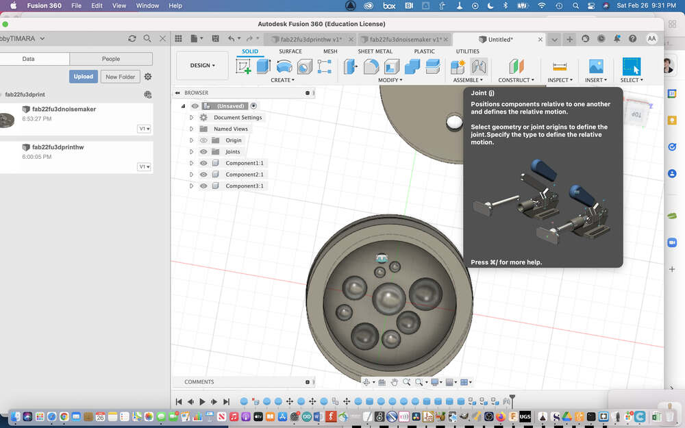
I began by creating several spheres, and then a cylinder at the base. I used the cylinder of the base to create an even plane, and then created a hollow cylinder to join to the base. I also created a top and made all of the items or objects that I created into components and assembled them into one object.
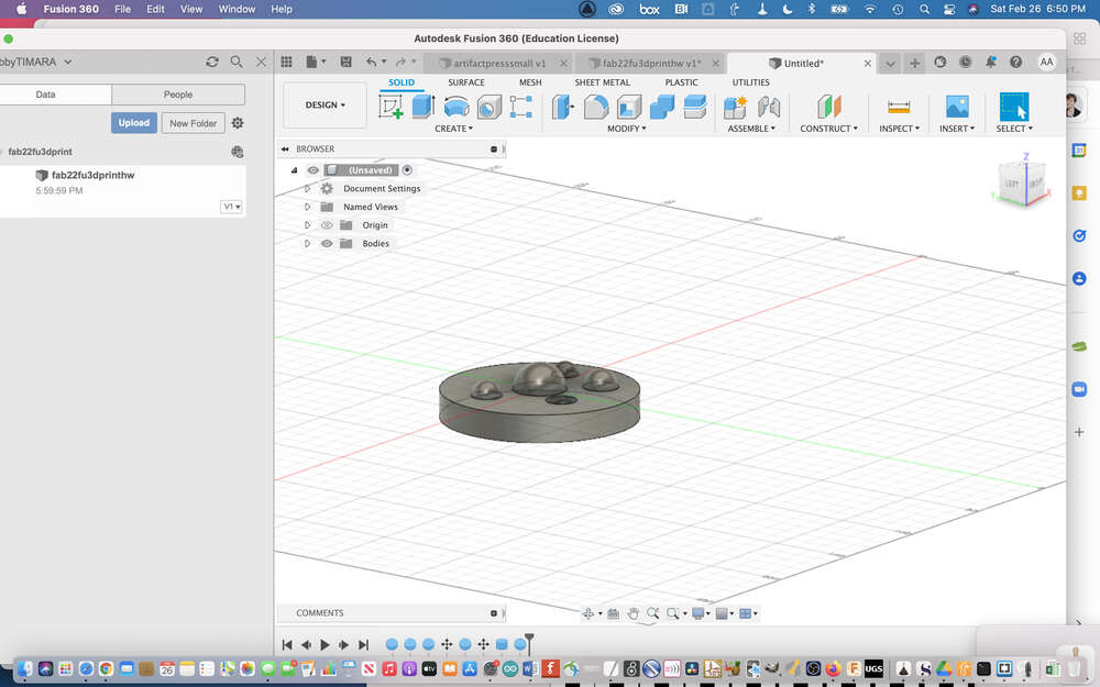
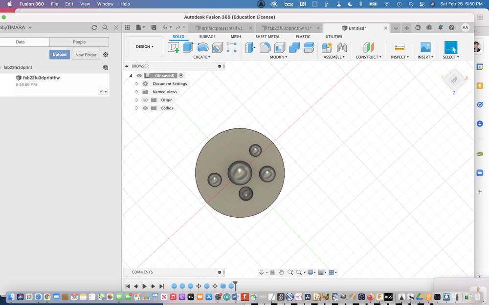


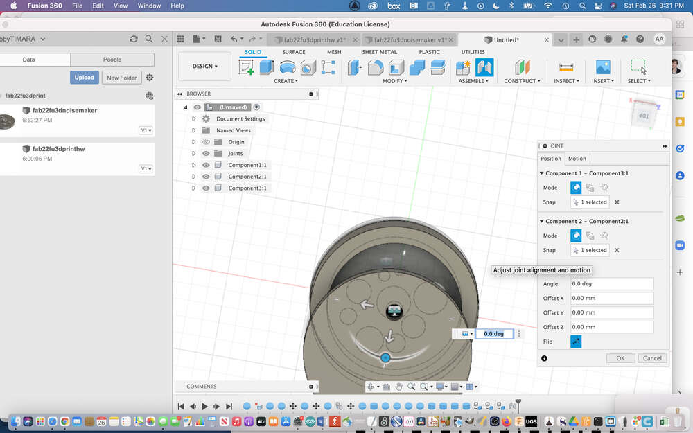
I wanted to print an object that was solid on the outside but hollow in the middle. I also wanted the object to be standing on its side because it was a wide cylinder that I thought would not be able to print successfully with the flat portions touching the print bed. (I thought the bridge distance from one side of the cylinder to the other would be much too long.) I turned on supports, and tried printing the object. Unfortunately, the printer was printing material on the inside of my object. I showed my instructor via a photograph, and he thought that the problem was that I was using supports. I was not sure how to resolve this issue since supports seemed necessary…so I decided to abandon the model and try to design something else entirely.
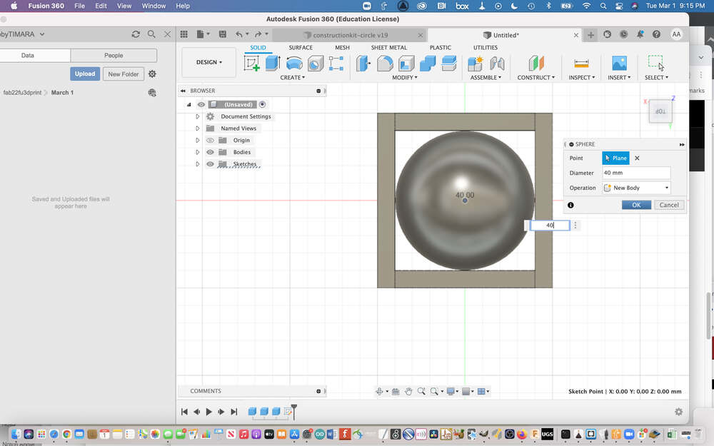
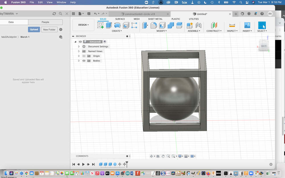
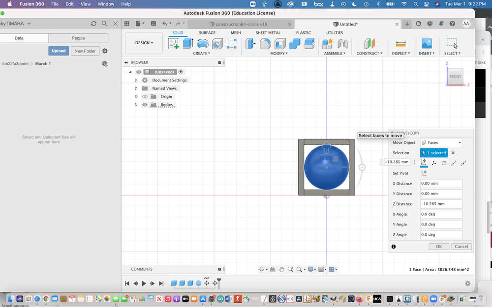
This is when I found this tutorial from Adrian Torres’ page. I tried to follow and tweak Adrian’s design For this week’s assignment. However, I misjudged the sizes of the cube and the sphere. I should have created a fully hollow cube so that the sphere could be larger and stick out the edges of the cube. The sphere I created fell straight through the cube as soon as you picked it up. I also was really excited about mesh mixer that Adrian used, but I wasn’t able to figure out how to even install it on a Mac. So, I hope to revisit this assignment in order to create something a bit more interesting, and a bit more personalized.
Slicing Software
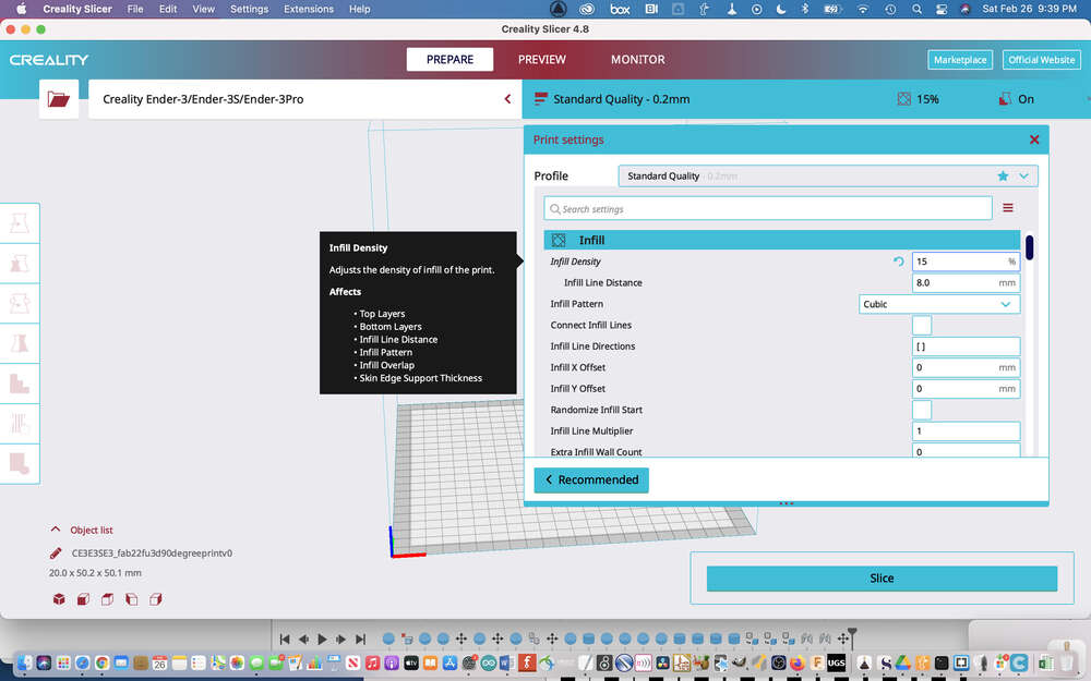
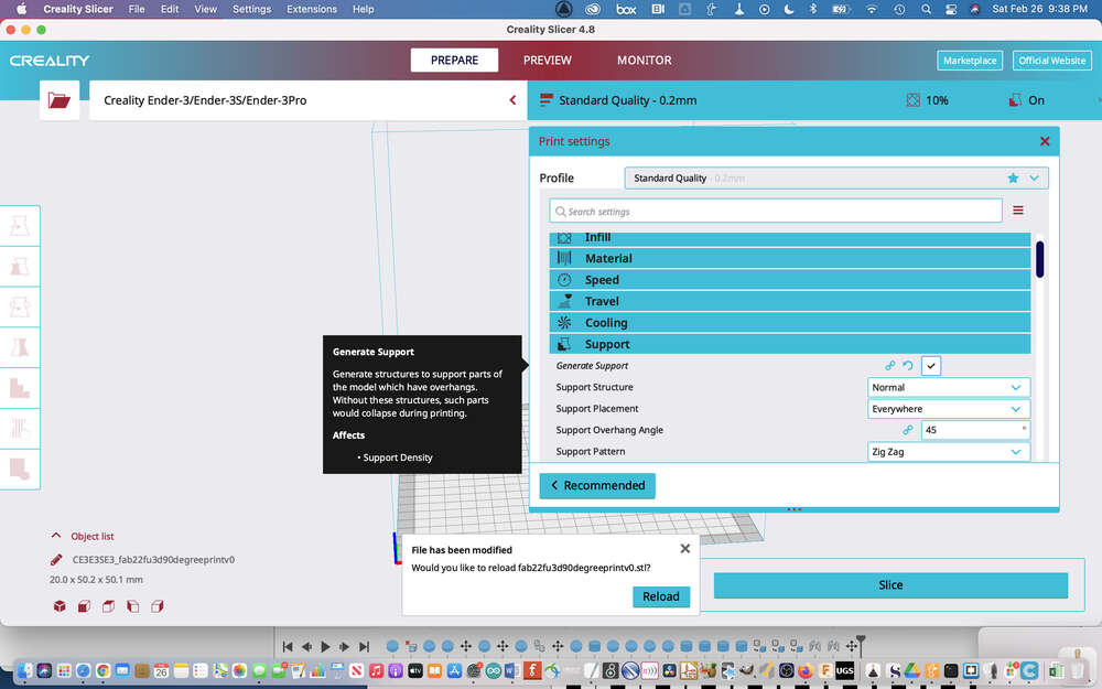
Within the slicing software, there are many different parameters that you can adjust. These address aspects of your print like whether there are any supports generated, the infill percentage, and much more.
A lot of these details need to be tweaked in menus. I have included a few examples below. I still have a lot to learn in terms of the broader range of parameters that can be adapted in this software.

Preparing Your 3D Printer
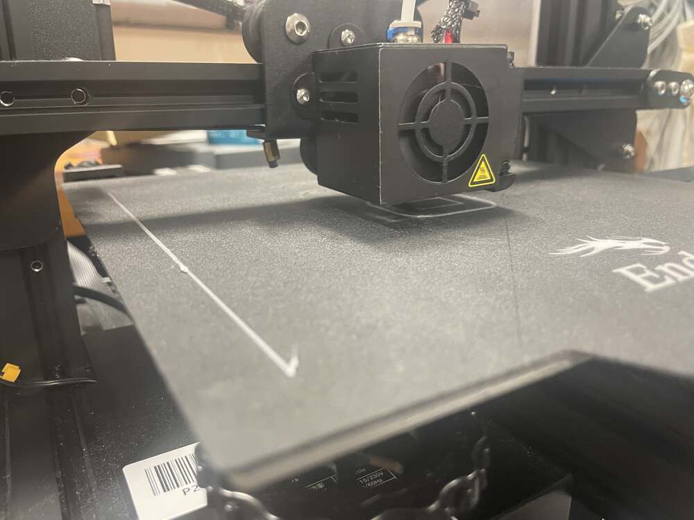
For this assignment, I am using an Ender Pro 3. Before you can begin printing, you must ensure that your filament is loaded onto the machine correctly. If you have old filament in your machine that you need to exchange for a fresh batch, you will need to first remove and purge this filament. To remove filament safely, you need to begin by heating the nozzle so that the filament may be removed without risking damage to the machine.
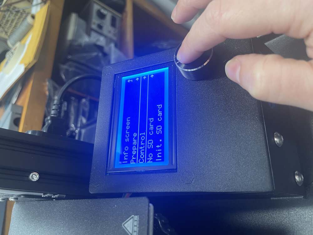
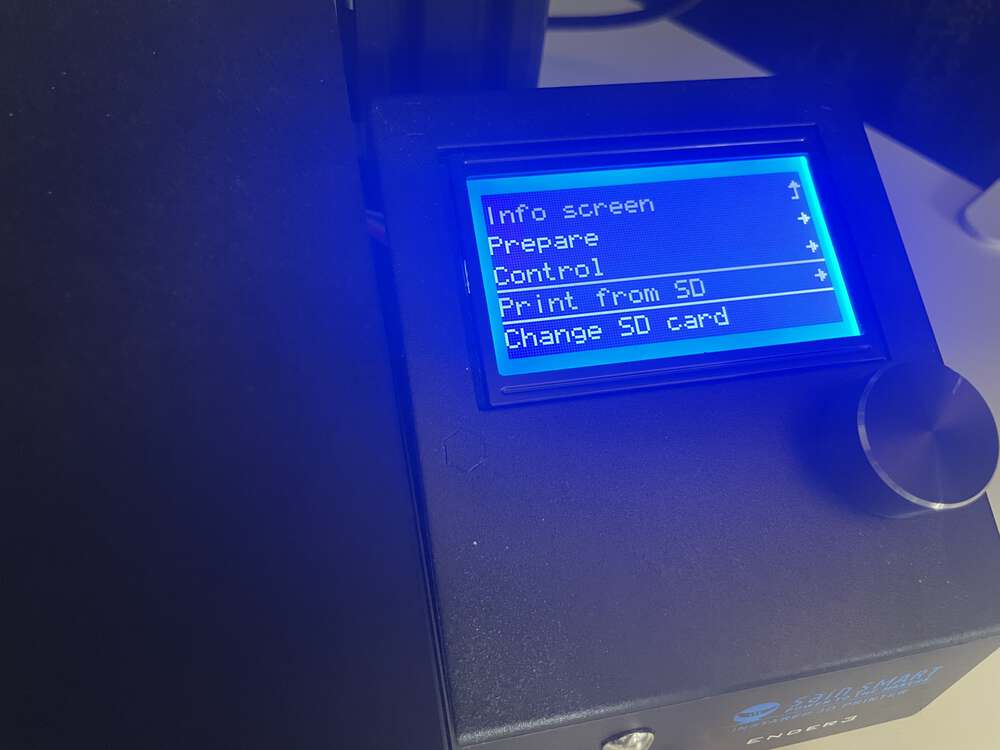
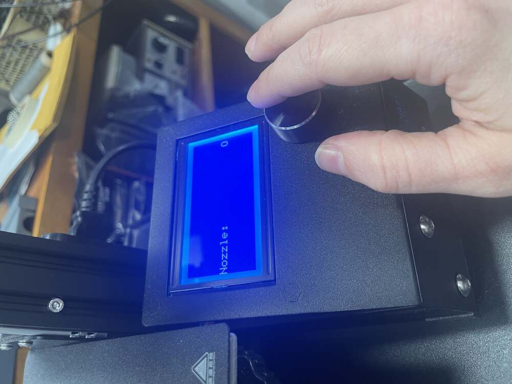
Click on the menu navigation tool. The navigation tool is the knob underneath the LCD screen. Pressing the knob will take you to a menu which you can navigate by turning and by clicking the knob. You should select the “preheat nozzle” feature.
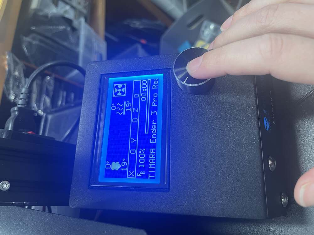
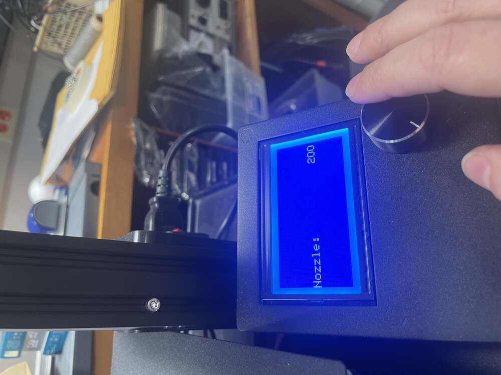
Preheat the nozzle to 200 degrees. Once the nozzle has reached 200, it is safe to remove the existing filament.
Begin by squeezing the clamp near the top of your machine where the filament is fed through. Pull on the filament while you are holding clamp in order to release the existing filament.
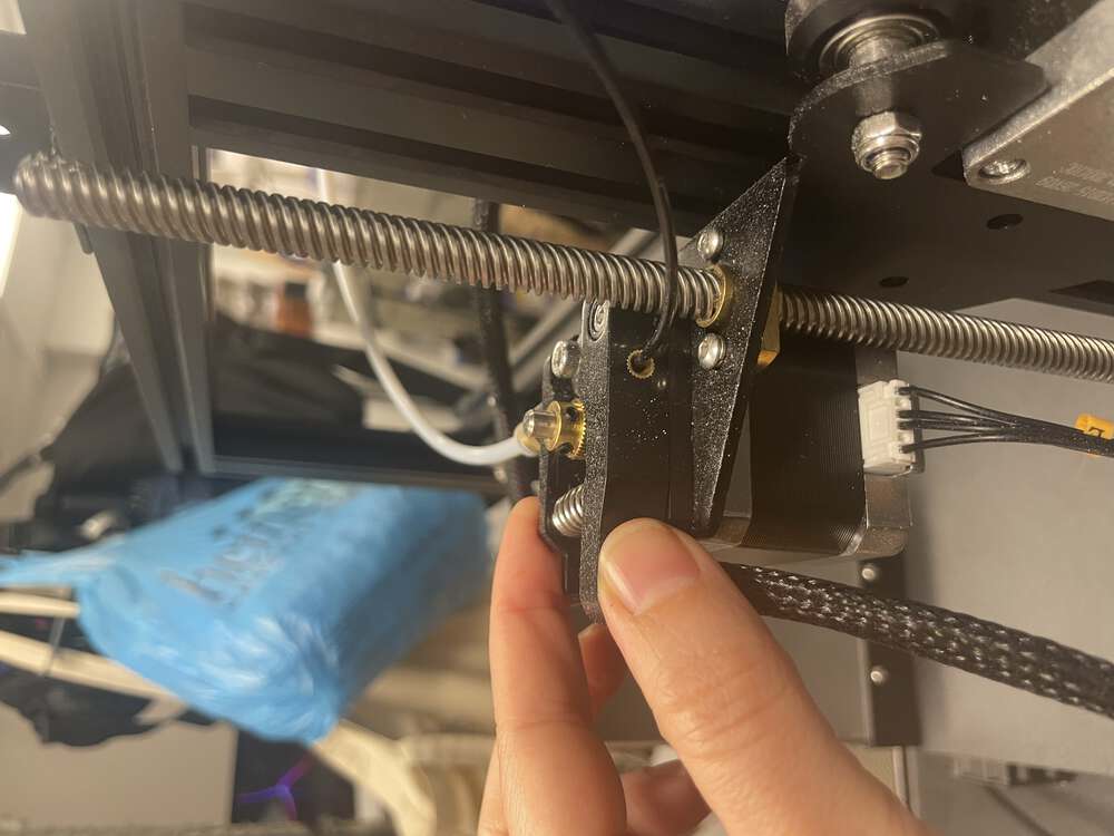
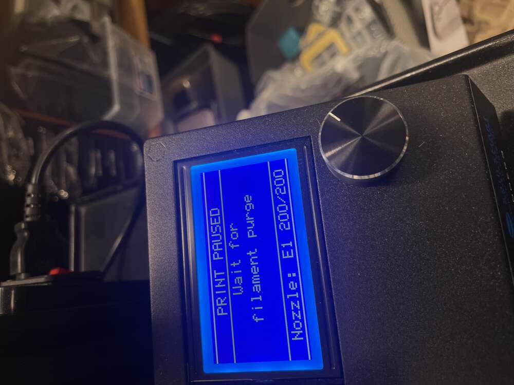
You may also discover that you need to use the filament purge option, which you can also find in the menu. The filament purge option allows you to clear out your machine of old filament. Occasionally, I have found it necessary to remove the filament tube at the brass hardware connection in order to release particularly stubborn filament.
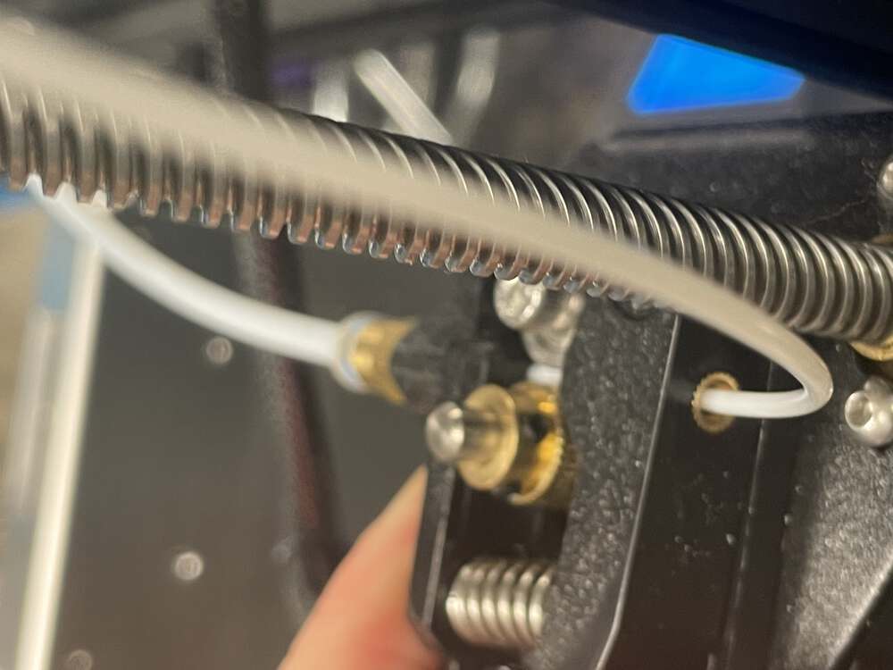
Different 3D printers have different methods for feeding the filament into the machine. While I generally like the design of the Ender Pro 3, this particular feature of the machine seems less than ideal. I find it very difficult to feed the filament into the machine. To have any chance of success, you must cut your filament at a 45-degree angle. You then need to make sure the filament is twisted such that the 45-degree angle helps to feed the filament into the machine. Do this in a well-lit area for best outcomes.
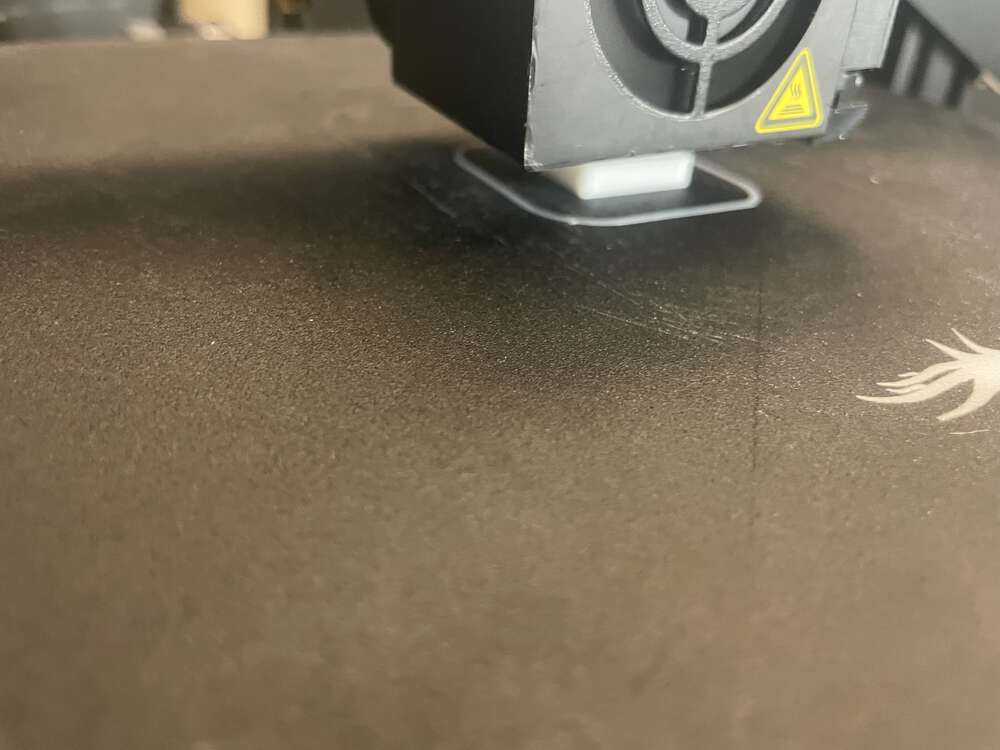
Once you have changed the filament, it is time to level the bed of the machine. I’ve found many different tutorials about leveling the bed of the 3D printer, several of which used a method where you disable the stepper motors. On some versions of the Ender Pro 3, it seems that this approach is the only option. This is unfortunate, because some sources suggested that disabling the stepper motor could be problematic, because the Z axis might ultimately drift when the motor is disabled. Wherever possible, I prefer to use the ‘level corners’ option in the menu. Begin by auto homing your machine. Then navigate to the level corners option in the hardware LCD screen menu. Next, make sure to have a piece of paper handy. Click on the level corners and ensure that at each corner you adjust the height of the bed with the knobs underneath, so that the piece of paper just barely fits under the nozzle at each corner. If you level your bed properly, the print adhesion should work well. By which I mean that as your printer begins the print, the material it generates will stick to the bed of the printer. You do need to be careful not to level your 3D printer such that the nozzle is too close to the bed. If the nozzle is too close, it can cause issues with the extrusion of the filament and also ruin a printing bed if the filament gets pressed too strongly into the bed.
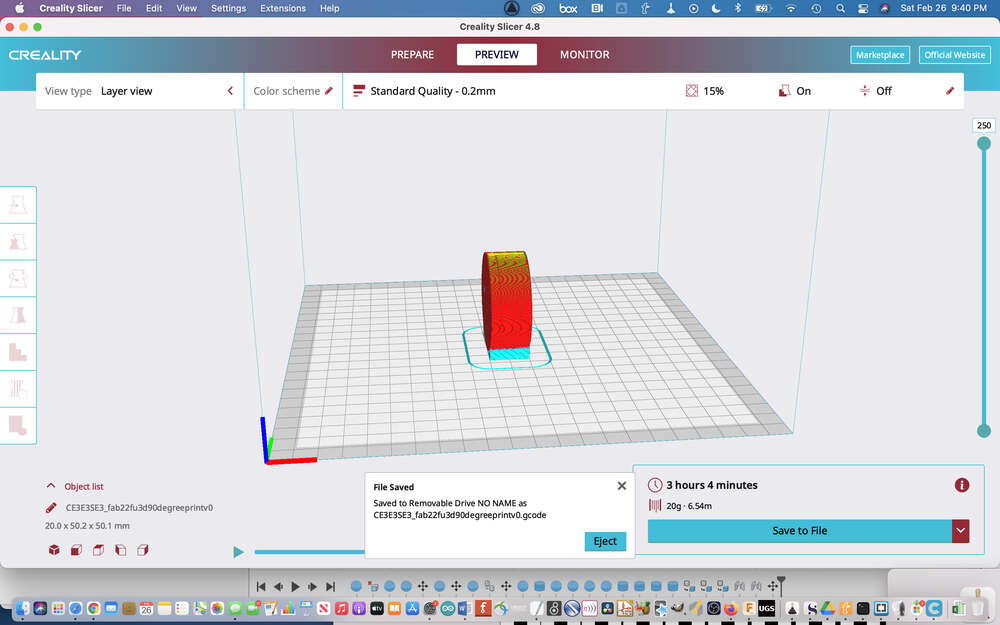
If all goes well, at the end of this process (which can take a very long time!) you will have a 3-dimensional object just like the one you designed, which is pretty nifty!
3D Scanning Process
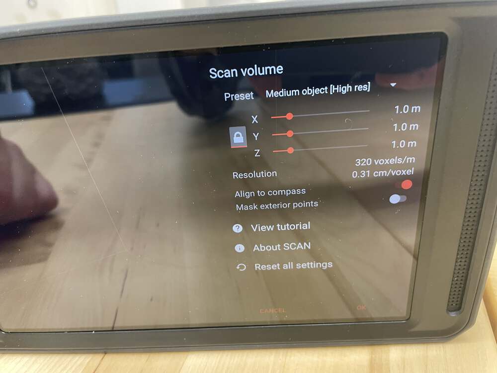
I used the Knockout scanner to create my 3D scan. This is an Andriod-based tablet scanner. It looksl like a Kinect with a screen attached to it. We went to the 3-D print lab and used a large Halloween gargoyle and placed it on a table. We had to choose the size of the scan box in the software. It was important that the box is a little bit larger than the object we were trying to scan so that the entirety of the object would fit into the box. We also did not want to make the box too large and accidentally get other items in the box. After choosing the scan box size I began taking the scan. In order to scan the object you wait until the image becomes green and then slowly move 360° around the object while also trying to get angles from above and below as best as you can. After completing the scan of the object you uploaded it to the school’s Google Drive account and then one of the instructors sent that object file to my email. I was struck by how difficult it was to scan smaller objects. I had sort of assumed that any size object would be relatively similar in terms of ease of scan. However, that was not the case. Medium objects at somewhat of a human scale seemed to be the easiest for scanning. Larger objects were awkward to scan and smaller objects difficult.
I used a knockout scanner with a large Halloween gargoyle my instructors had on hand for this purpose:

Here I am adjusting the scan volume on the 3d scanner:
NEED TO TRY TO PREPARE FOR PRINTING NEED TO TRY TO PREPARE FOR PRINTING NEED TO TRY TO PREPARE FOR PRINTING
Group Project
Our documentation for our 3D printing group work is here. You can find Neil’s STL files here. We used these files to test the capabilities of my Ender Pro 3. Printing these files individually helped me to understand some of the limitations associated with 3D printing. From this process, a few things stood out to me. First, I noticed challenges associated with printing at right angles without supports. This made me realize that it would be wise to design objects for printing with this in mind and to aim to avoid designing objects with long, unsupprted, 90-degree protrusions. Another important element to note is that print sizes are not always perfectly accurate. When designing parts that are intended to fit together, it is important to have a good sense for the tolerances of your machine and how accurate your print sizes will be. I was pretty impressed with the accuracy of the Ender Pro 3 given that it is a consumer-grade machine.
Below, I outline my contributions to the group project in more detail.
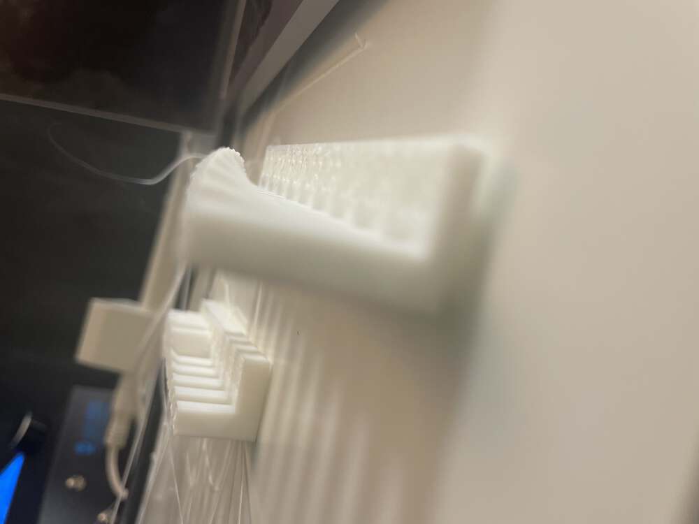
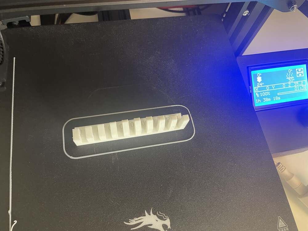
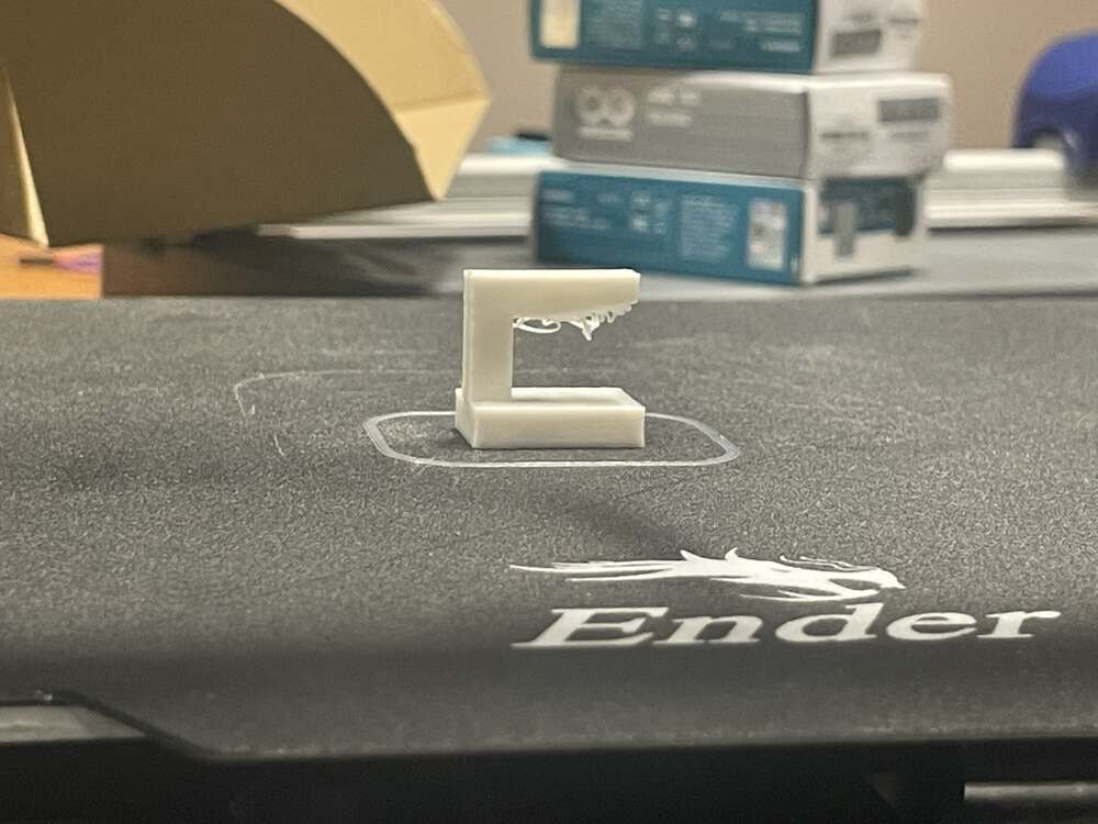
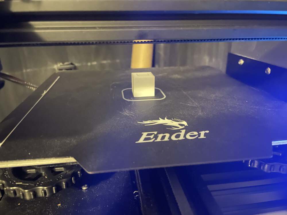
To test the design rules of the 3D printer, I printed several of the .stl files provided on the fab Academy website. The first STL file that I printed was a small piece with a hard right angle that was unsupported. The underside of the unsupported section clearly failed as a print and illustrated that unsupported prints at 90° angles are likely to fail.
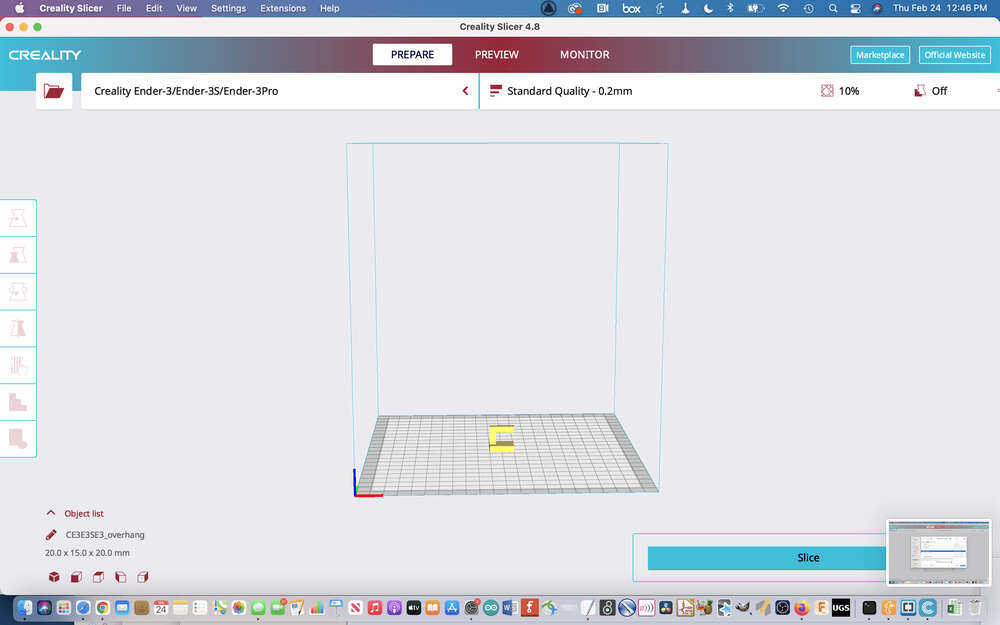
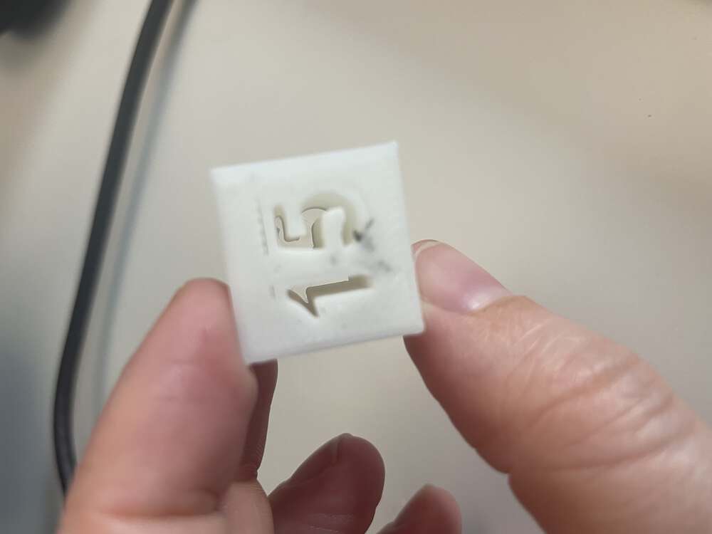
The next print I tried was the 15% in fill. However, I am new to 3D printing, and I did not understand the purpose of this print, and did not know that I needed to change the infill, nor where I would change that. My instructor subsequently demonstrated to me how to change several of the settings in the Creality Slicer 3-D print software. I hope to reprint the infill test at 15%; The original print was completed at 10% infill.
A subsequent cube that I printed I had listed measurements of 10 and 20 mm. I did not understand what this print was intended to convey until my instructor helped me to understand that I needed to measure the inner and outer diameters to understand whether the 3D print was true to size. We measured the print with calipers and discovered it was very close to correct on both the inner and outer measurements.
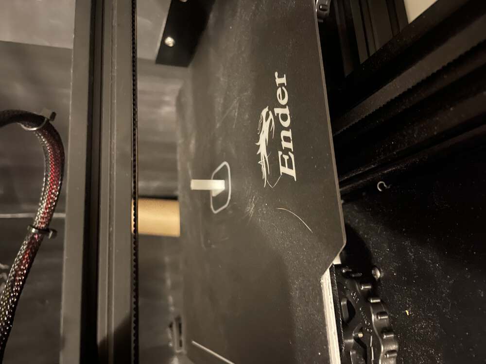
Below is another 90° angle print. However, this time the base is long and thin and the print build goes straight up. My instructor said that sometimes such a small print area can be problematic because the PLA does not have enough time to cool down as it is printing if the printhead is moving over the same spot so regularly.
The finish test came out very oddly for my printer and my instructor was initially very confused by the poor quality. I did not have my printer with me in the lab,
but my instructor was able to hypothesize, correctly I think, that one or more of the belts on my printer is likely loose. It does appear to be loose and I will aim to fix that in the coming week.

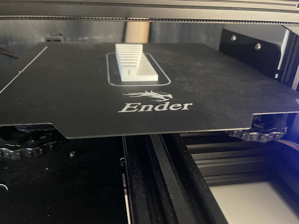
When I first began this angle print, I accidentally selected the generate supports option. This was something that my instructor was showing me to manipulate in the slicer for other projects, and I forgot to turn it off before I printed the angle test. So I aborted that print and start it over. I was actually extremely impressed by the angle support test; it seems like it worked actually very effectively except for the 10 and 0° angles, My assumption is that these are actually 90° and maybe 80° rather than 10 and zero. (I’m not sure I understand the numbering system they are using here.)
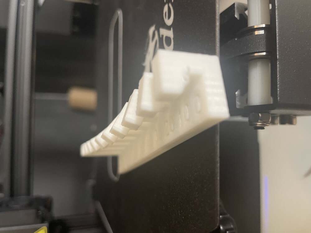
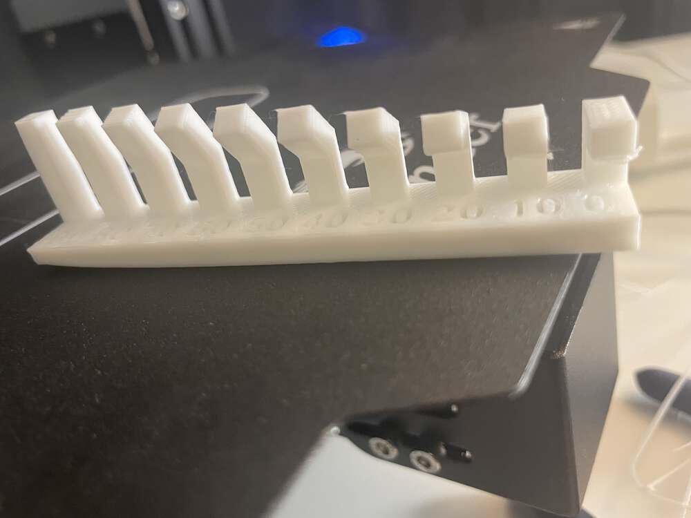
The overhang test is another variation on a similar theme where we are testing how far out a 90-degree protusion can extend before failing without additional supports.
Below are a few additional photos of the group project 3D prints: