9. Embedded programming
Our Homework this week:
Our assignment this week is to:
Group assignment:
- Compare the performance and development workflows for other architectures
- Document your work to the group work page and reflect on your individual page what you learned
Individual assignment:
- Read the datasheet for your microcontroller
- Use your programmer to program your board to do something
- Learning outcomes
- Identify relevant information in a microcontroller datasheet.
- Implement programming protocols.
Have you answered these questions?
- Linked to the group assignment page
- Documented what you learned from reading a microcontroller datasheet.
- Programmed your board
- Described the programming process/es you used
- Included your source code
- Included a short ‘hero video’ of your board
Reading the data sheet
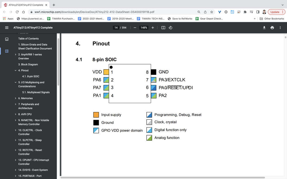
While I have looked at many data sheets in the past in order to determine pin outs and other basic information about integrated circuits, I have never tried to read a significant portion of a data sheet. There is quite a lot that I don’t understand. I find it very helpful to have the table of contents open on the left in order to understand how each section relates to other sections of the data sheet.
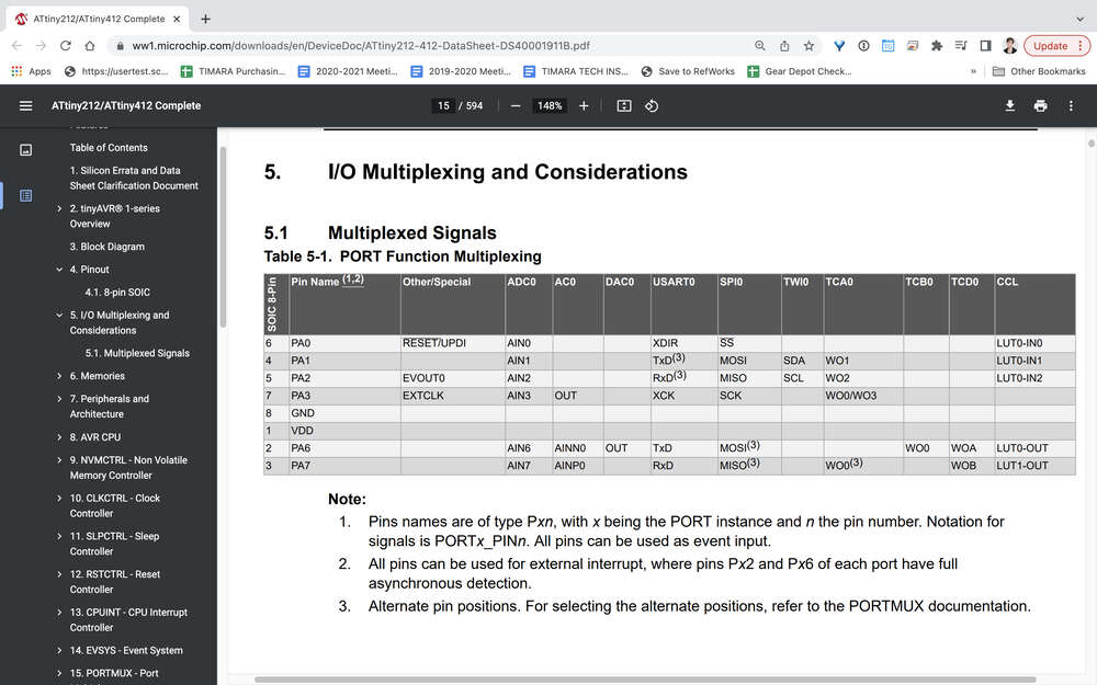
What I have found most useful, is to skip around and to revisit sections of the data sheet after having read through other sections. For example the block diagram is a bit confusing and overwhelming initially. It begins to make a bit more sense after reading some of the other sections that touch on elements that are incorporated into the block diagram. Wow I wouldn’t go so far as to say that I understood the block diagram, I think it is fair to say that I at least recognize some of the different elements that are incorporated into it. For example you can see the ADC and DAC represented — these stand for analog to digital and digital to analog converter’s respectively.
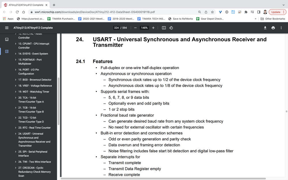
The USART block connects to RX, TX, XCK, and XDIR. I know that RX and TX at least are on separate pins for receiving and transmitting data respectively.
https://ccrma.stanford.edu/wiki/Microcontroller_Architecture#:~:text=A%20microcontroller%20is%20essentially%20a,interfaces%20into%20a%20single%20chip.
Programming the Board
Code
I began by circling back to the example code we used to test my board previously. I started by just changing durations
/*
  Blink

  Turns an LED on for one second, then off for one second, repeatedly.

  Most Arduinos have an on-board LED you can control. On the UNO, MEGA and ZERO
  it is attached to digital pin 13, on MKR1000 on pin 6. LED_BUILTIN is set to
  the correct LED pin independent of which board is used.
  If you want to know what pin the on-board LED is connected to on your Arduino
  model, check the Technical Specs of your board at:
  https://www.arduino.cc/en/Main/Products

  modified 8 May 2014
  by Scott Fitzgerald
  modified 2 Sep 2016
  by Arturo Guadalupi
  modified 8 Sep 2016
  by Colby Newman

  This example code is in the public domain.

  https://www.arduino.cc/en/Tutorial/BuiltInExamples/Blink
*/

// the setup function runs once when you press reset or power the board
void setup() {
  // initialize digital pin LED_BUILTIN as an output.
  pinMode(2, OUTPUT);
}

// the loop function runs over and over again forever
void loop() {
  digitalWrite(2, HIGH);   // turn the LED on (HIGH is the voltage level)
  delay(500);                       // wait for a second
  digitalWrite(2, LOW);    // turn the LED off by making the voltage LOW
  delay(2000);                       // wait for a second

}
Next, I decided to try to get both LEDs blinking. I starting with different durations in sequence ``` /* Blink
Turns an LED on for one second, then off for one second, repeatedly.
Most Arduinos have an on-board LED you can control. On the UNO, MEGA and ZERO it is attached to digital pin 13, on MKR1000 on pin 6. LED_BUILTIN is set to the correct LED pin independent of which board is used. If you want to know what pin the on-board LED is connected to on your Arduino model, check the Technical Specs of your board at: https://www.arduino.cc/en/Main/Products
modified 8 May 2014 by Scott Fitzgerald modified 2 Sep 2016 by Arturo Guadalupi modified 8 Sep 2016 by Colby Newman
This example code is in the public domain.
https://www.arduino.cc/en/Tutorial/BuiltInExamples/Blink */
// the setup function runs once when you press reset or power the board void setup() { // initialize digital pin LED_BUILTIN as an output. pinMode(2, OUTPUT); pinMode(4, OUTPUT); }
// the loop function runs over and over again forever void loop() { digitalWrite(2, HIGH); // turn the LED on (HIGH is the voltage level) delay(1000); // wait for a second digitalWrite(2, LOW); // turn the LED off by making the voltage LOW delay(500); // wait for a second
digitalWrite(4, HIGH); // turn the LED on (HIGH is the voltage level)
delay(1000); // wait for a second digitalWrite(4, LOW); // turn the LED off by making the voltage LOW delay(500); // wait for a second
} ``` Then had them blinking simultaneously:
``` /* Blink
Turns an LED on for one second, then off for one second, repeatedly.
Most Arduinos have an on-board LED you can control. On the UNO, MEGA and ZERO it is attached to digital pin 13, on MKR1000 on pin 6. LED_BUILTIN is set to the correct LED pin independent of which board is used. If you want to know what pin the on-board LED is connected to on your Arduino model, check the Technical Specs of your board at: https://www.arduino.cc/en/Main/Products
modified 8 May 2014 by Scott Fitzgerald modified 2 Sep 2016 by Arturo Guadalupi modified 8 Sep 2016 by Colby Newman
This example code is in the public domain.
https://www.arduino.cc/en/Tutorial/BuiltInExamples/Blink */
// the setup function runs once when you press reset or power the board void setup() { // initialize digital pin LED_BUILTIN as an output. pinMode(2, OUTPUT); pinMode(4, OUTPUT); }
// the loop function runs over and over again forever
void loop() {
digitalWrite(2, HIGH); // turn the LED on (HIGH is the voltage level)
digitalWrite(4, HIGH); // turn the LED on (HIGH is the voltage level)
delay(1000); // wait for a second
digitalWrite(4, LOW); // turn the LED off by making the voltage LOW
digitalWrite(2, LOW); // turn the LED off by making the voltage LOW
delay(500); // wait for a second
}
Next, I tried the button arduino example:
/* Button
Turns on and off a light emitting diode(LED) connected to digital pin 13, when pressing a pushbutton attached to pin 2.
The circuit: - LED attached from pin 13 to ground through 220 ohm resistor - pushbutton attached to pin 2 from +5V - 10K resistor attached to pin 2 from ground
- Note: on most Arduinos there is already an LED on the board attached to pin 13.
created 2005 by DojoDave http://www.0j0.org modified 30 Aug 2011 by Tom Igoe
This example code is in the public domain.
https://www.arduino.cc/en/Tutorial/BuiltInExamples/Button */
// constants won’t change. They’re used here to set pin numbers: const int buttonPin = 3; // the number of the pushbutton pin const int ledPin = 2; // the number of the LED pin
// variables will change: int buttonState = 0; // variable for reading the pushbutton status
void setup() { // initialize the LED pin as an output: pinMode(ledPin, OUTPUT); // initialize the pushbutton pin as an input: pinMode(buttonPin, INPUT); }
void loop() { // read the state of the pushbutton value: buttonState = digitalRead(buttonPin);
// check if the pushbutton is pressed. If it is, the buttonState is HIGH: if (buttonState == HIGH) { // turn LED on: digitalWrite(ledPin, HIGH); } else { // turn LED off: digitalWrite(ledPin, LOW); } }
This actually functioned in reverse, which tells me that my button state is normally high.I swapped the LED highs and lows to be certain:
/* Button
Turns on and off a light emitting diode(LED) connected to digital pin 13, when pressing a pushbutton attached to pin 2.
The circuit: - LED attached from pin 13 to ground through 220 ohm resistor - pushbutton attached to pin 2 from +5V - 10K resistor attached to pin 2 from ground
- Note: on most Arduinos there is already an LED on the board attached to pin 13.
created 2005 by DojoDave http://www.0j0.org modified 30 Aug 2011 by Tom Igoe
This example code is in the public domain.
https://www.arduino.cc/en/Tutorial/BuiltInExamples/Button */
// constants won’t change. They’re used here to set pin numbers: const int buttonPin = 3; // the number of the pushbutton pin const int ledPin = 2; // the number of the LED pin
// variables will change: int buttonState = 0; // variable for reading the pushbutton status
void setup() { // initialize the LED pin as an output: pinMode(ledPin, OUTPUT); // initialize the pushbutton pin as an input: pinMode(buttonPin, INPUT); }
void loop() { // read the state of the pushbutton value: buttonState = digitalRead(buttonPin);
// check if the pushbutton is pressed. If it is, the buttonState is HIGH: if (buttonState == HIGH) { // turn LED on: digitalWrite(ledPin, LOW); } else { // turn LED off: digitalWrite(ledPin, HIGH); } }
 ...and indeed, this worked as expected, if with some latency.

 Next I wrote my own version combining the two examples:

 ```


const int led1 =  2;      // the number of the LED pin #1
const int button = 3;     // the number of the button pin
const int led2 = 4; // the number of the LED pin #2
int buttonState = 0;

void setup() {
 //setting up pin modes
  pinMode(led1, OUTPUT);
  pinMode(led2, OUTPUT);
  pinMode(button, INPUT);

}

void loop() {
  // put your main code here, to run repeatedly:
  buttonState = digitalRead(button);

  if (buttonState == HIGH) {
  digitalWrite(led1, HIGH);   // turn the LED on (HIGH is the voltage level)
  digitalWrite(led2, HIGH);   // turn the LED on (HIGH is the voltage level)
  delay(1000);                       // wait for a second
  digitalWrite(led2, LOW);    // turn the LED off by making the voltage LOW
  digitalWrite(led1, LOW);    // turn the LED off by making the voltage LOW
  delay(500);
  } else {

 digitalWrite(led1, HIGH);   // turn the LED on (HIGH is the voltage level)
  delay(1000);                       // wait for a second
  digitalWrite(led1, LOW);    // turn the LED off by making the voltage LOW
  delay(500);                       // wait for a second

    digitalWrite(led2, HIGH);   // turn the LED on (HIGH is the voltage level)
  delay(1000);                       // wait for a second
  digitalWrite(led2, LOW);    // turn the LED off by making the voltage LOW
  delay(500);
  }
  }
Lastly, I wanted to experiment with adjusting the output based on different numbers of button presses. This tutorial was very helpful: https://www.circuitgeeks.com/arduino-push-button-tutorial/. To count button presses, you have to check whether the last state is different from the current state.
I tried this example from the site, modified for my board:
``` int ledPin[2] = {2, 4};
const int buttonPin = 3; int buttonState = HIGH; int pushCounter = 0; int numberOfLED = 2; void setup() { pinMode(buttonPin, INPUT); for (int i = 0; i <= 2; i++) { pinMode(ledPin[i], OUTPUT); } }
void loop() { buttonState = digitalRead(buttonPin); if (buttonState == LOW) { for (int i = 0; i < numberOfLED; i++) { if (pushCounter % numberOfLED == i) { digitalWrite(ledPin[i], HIGH); } else { digitalWrite(ledPin[i], LOW); } } pushCounter++; delay(400); } }
And got alternating blinking LEDs on a press which wasn't what I expected. I decided to try out serial communication to see if I was actually getting the expected data. Unfortunately, serial communication did not appear to be working at all.
const int buttonPin = 3; int currentState; // variable for reading the pushbutton status int pushCounter = 0; // counter for the number of button presses int lastState = HIGH; // previous state of the button
void setup() { Serial.begin(115200); Serial.println(“Push Button Counter”); Serial.println(” “); pinMode(buttonPin, INPUT); }
void loop() { currentState = digitalRead(buttonPin); if (currentState != lastState) { if (currentState == LOW) { pushCounter++; Serial.print(“Button Press Count = “); Serial.println(pushCounter); } } lastState = currentState; if (pushCounter >= 10) { Serial.println(” “); Serial.println(“Resettng the Counter…”); pushCounter = 0; } delay(50); }
"Lorem ipsum dolor sit amet, consectetur adipiscing elit, sed do eiusmod tempor incididunt ut labore et dolore magna aliqua. Ut enim ad minim veniam, quis nostrud exercitation ullamco laboris nisi ut aliquip ex ea commodo consequat. Duis aute irure dolor in reprehenderit in voluptate velit esse cillum dolore eu fugiat nulla pariatur. Excepteur sint occaecat cupidatat non proident, sunt in culpa qui officia deserunt mollit anim id est laborum."

> "Lorem ipsum dolor sit amet, consectetur adipiscing elit, sed do eiusmod tempor incididunt ut labore et dolore magna aliqua. Ut enim ad minim veniam, quis nostrud exercitation ullamco laboris nisi ut aliquip ex ea commodo consequat. Duis aute irure dolor in reprehenderit in voluptate velit esse cillum dolore eu fugiat nulla pariatur. Excepteur sint occaecat cupidatat non proident, sunt in culpa qui officia deserunt mollit anim id est laborum."

## Useful links

- [Jekyll](http://jekyll.org)
- [Google](http://google.com)
- [Markdown](https://en.wikipedia.org/wiki/Markdown)

## Code Example

Use the three backticks to separate code.
// the setup function runs once when you press reset or power the board void setup() { // initialize digital pin LED_BUILTIN as an output. pinMode(LED_BUILTIN, OUTPUT); }
// the loop function runs over and over again forever void loop() { digitalWrite(LED_BUILTIN, HIGH); // turn the LED on (HIGH is the voltage level) delay(1000); // wait for a second digitalWrite(LED_BUILTIN, LOW); // turn the LED off by making the voltage LOW delay(1000); // wait for a second } ```
Gallery

Video
From Vimeo
Sound Waves from George Gally (Radarboy) on Vimeo.