8. Computer controlled machining
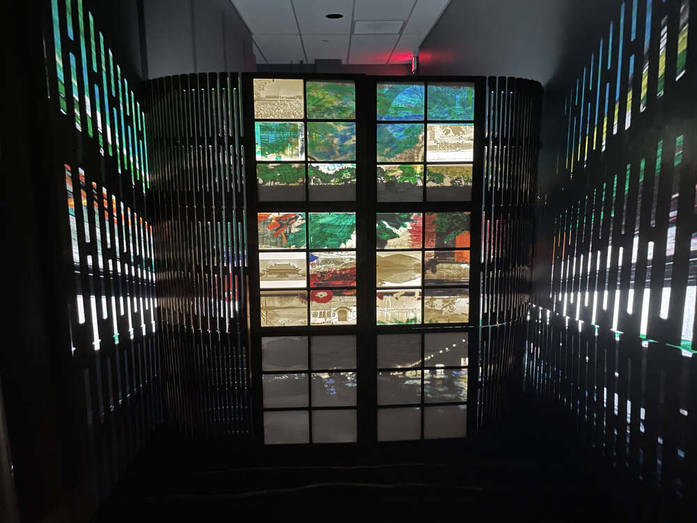 Hero shot of a multimodal sculpture featuring 3D printed lithophanes with animated, projection-mapped paintings. This was a collaborative project. For the ‘make something big’ assignment, I designed and machined the frame.
Our Homework this week:
Our assignment this week is to:
Group assignment:
- Complete your lab’s safety training
- Test runout, alignment, speeds, feeds, and toolpaths for your machine
- Document your work to the group work page and reflect on your individual page what you learned
Individual project
- Make (design+mill+assemble) something big

Learning outcomes
- Demonstrate 2D design development for CNC production
- Describe workflows for CNC production
Have you answered these questions?
- Linked to the group assignment page
- Documented how you designed your object (something big)
- Documented how you made your CAM-toolpath
- Documented how you made something BIG (setting up the machine, using fixings, testing joints, adjusting feeds and speeds, depth of cut etc.)
- Described problems and how you fixed them
- Included your design files and ‘hero shot’ photos of final object
A bit about the big thing I made
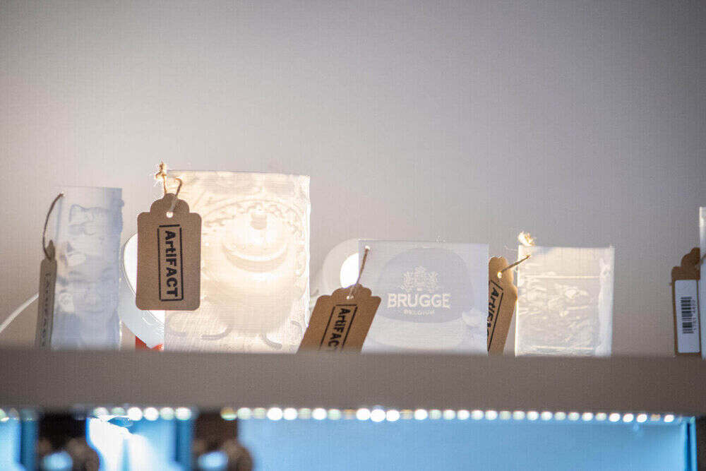
For the ‘make something big’ assignment, I designed and machined the frame for a multimodal, collaborative sculpture. The piece was shared at the conclusion of a workshop series that brought senior citizens and ESOL students together to share stories about important places in their lives. The sculpture features 3D printed lithophanes of photographs shared by participants and animated projections of paintings they made. You can read more about the ArtiFACT project here and here.
The following photographs show the 3D printed lithophanes featuring participants’ photographs lit from behind. The lithophanes are created with online software that uses the images provided to automatically create a print with depths that vary based on the varying levels of light and dark sections found within each image:
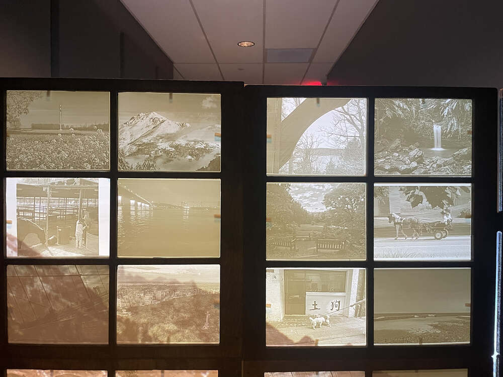
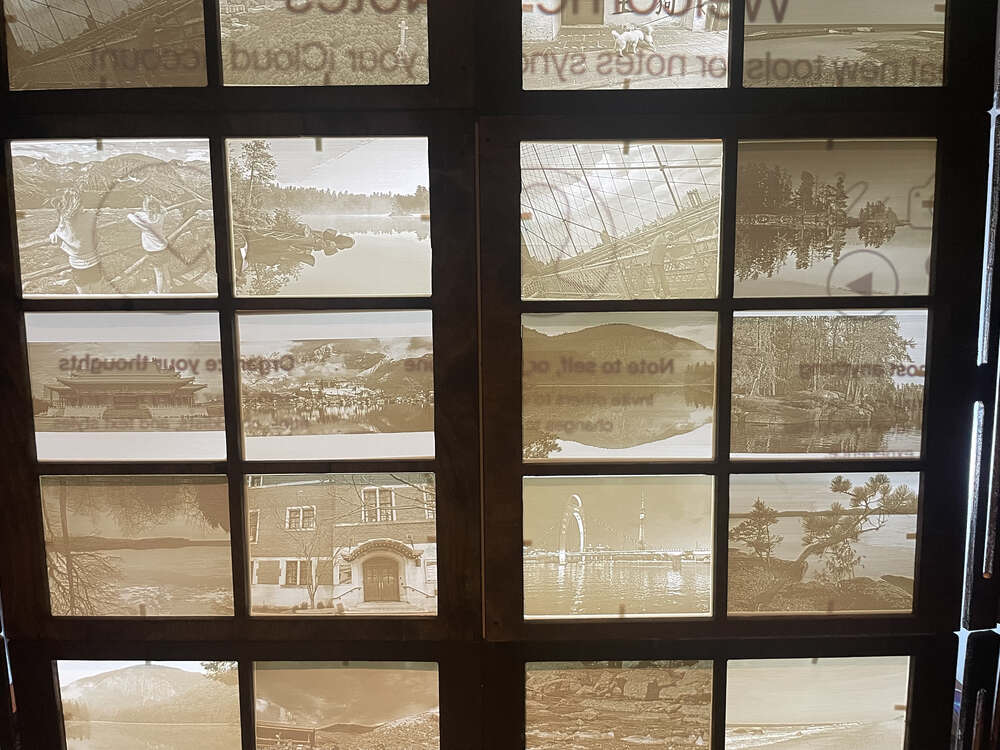
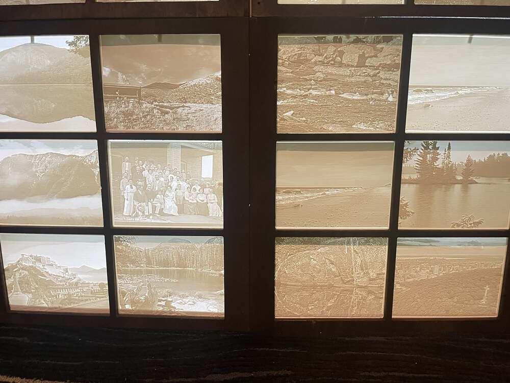
And here are a few close ups:


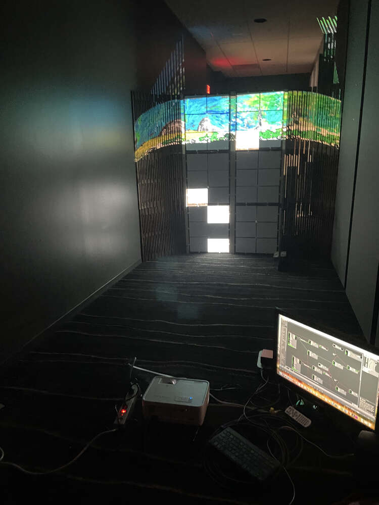
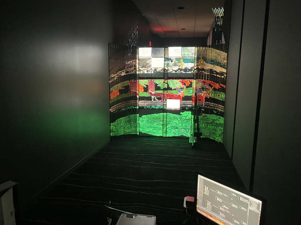
In these two images below, you can see the tech setup for the installation. A computer running Isadora feeds a single projector that maps the paintings to the display:
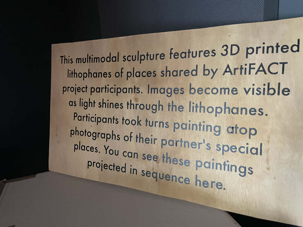
A sign describes the project:
In addition to the workshop participants themselves, many people assisted with this project. My colleague Abe Reshad and his assistants printed the lithophanes. With support from Oberlin College, student research assistants Maya McCollum, Ivy Fu, Lily Lansdell, Gabe Baskin, Michael Gaspari, and volunteer Joshua Reiner helped with workshops, scanning, animation, assembly, and projection mapping, among other tasks. Members of the theater department’s technical crew also assisted with assembly in the space. Much gratitude to past ArtiFACT assistants including Lucas Brecher, Helen He, Sarah Goodstein, and Olivia Lu. Many thanks to my longtime ArtiFACT collaborators, Larissa Fekete, Abe Reshad, and Al Evangelista, for their continued efforts on these workshops and collaborations.
Making Something Big - An Overview of the Process
To make something big, we build on some of the same 2D CAD design skills we have been practicing for weeks. However, for our assignment this week, there are a few important differences:
- Safety: Large format CNC machines like the Shopbot are very dangerous and can kill you if not handled with care. So, while following proper safety protocols is always critical, it is especially important for this week’s assignment.
- Engineering: When designing at this larger scale, we have to be a bit more intentional about our plans to make sure that fabricated designs will be stable and function as intended. It can be helpful to build a model of the final design at a smaller scale to see that it functions as intended.
- Tooling: When we used a small mill to cut our PCBs, we used only two endmills: a 1/64th endmill for the traces and a 1/32 endmill for cutting the perimeter. For this assignment, we have a lot more flexibility in deciding what types of tools we want to use to fabricate our design.
- Generating Toolpaths: After you create a design file in a program like Fusion, you need to do a bit more detailed translation between the file and the toolpaths than we have done thus far with modsproject.org. The ShopBot also requires a special file format. I tried out two programs, Aspire and Partworks, to generate the file I used on the ShopBot. In Partworks, Aspire, or another similar program, you will set up the tool paths, indicate the tooling and material thickness, add tabs, dog bones and t-bones, and set whether the cut runs on the inside or outside of the design.
- Running the machine: You need to go through the process of safely affixing materials to the bed atop a spoil board, ensuring material is level and squared to the machine and then zero the z-axis. Despite the very real safety concerns, I nevertheless found it sort of amusing to go from a tiny SainSmart mill to working on a Shopbot. It is definitely not exactly the same, but the steps in the process feel very familiar, only now they are giant whereas before they were in miniature. The large scale format, of course, demands close attention as the larger machines can injure and even kill you.
- Finishing: After you finish cutting your part on the CNC, you will need to reserve time to clean it up. This can include sanding, staining, assembly, as well as other miscellaneous woodworking tasks to get the raw cut assembled into your final design.
I’ll walk through each of these steps in much more detail below.
Safety
Below I have compiled a list of safety requirements regarding operating the ShopBot.
- Do not operate the machine without proper training. Never operate the machine alone. Never leave the machine while it is running.
- It is important to be well-rested, focused, and calm when using the machine. If you are feeling tired or distracted for any reason, you should not use the machine.
- You should have no loose clothing or jewelry and hair must be tied back so that no items on your body could get caught in the machine.
- You should wear eye protection and ear protection when operating the machine.
- Do not touch the machine bed when the machine is on.
- Do not touch the tool immediately after turning the machine off as it will be hot and you could burn yourself.
- Before you ever turn on the machine, find out where the emergency stop button is so that you can quickly turn off the machine should anything go wrong.
- When changing the tool, make sure that you adequately tighten it.
- Ideally use wood screws to affix stock to soil board. Even so, be careful that your tool path does not collide with screws used to affix stock to soil board.
- Seek advice regarding appropriate speeds, feeds, and depth of cut so as not to break a tool or cause stock to dislodge and fly loose.
- Make sure dust collection is on and functional and clean up all excess sawdust after each use.
Design Inspiration
This assignment took me a significant amount of time to complete, certainly more than a week. My goal for this assignment all along was to create a physical structure that would be used as part of an exhibit featuring images collected from and created by ArtiFACT project participants. However, I went through many different design phases before coming to the final structure pictured above.
The original lithophanes we created for the very first iteration of this project were curved so that they could stand on their own, like so:
I really loved the curved look and wanted to incorporate it into the larger design so that the structure would feel like one gigantic lithophane, kind of like this image a colleague and I came across online:

Said colleague, Abe Reshad, who has always managed the 3D printing of the lithophanes for this project, had mentioned the possibility of using colorized lithophanes in a future project iteration. Originally, all our lithophanes were in black and white. But the idea of colorizing the lithophanes made me think of the way people used to colorize black and white photos and film by hand. I had this idea of rear projecting hand-painted colorized versions of the lithophanes through the larger structure and mapping the images to both the smaller scale of a single lithophane and also, sometimes, to a larger scale to create a single lithophane showcasing one participants’ image and story.
Engineering: Early Designs
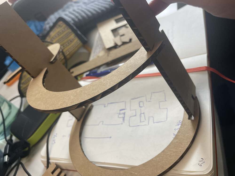
Initially, I planned reuse the design from my parametric cardboard press fit construction kit as the basis for the frame. However, using my parametrically designed cardboard construction kit to achieve this goal proved more complicated than I had imagined. I was concerned about the structural integrity of the design if I were to cut out of a heavier material like plywood. More importantly, I did not have a realistic plan for how to actually install the lithophanes within the structure. They would have each needed to be printed at a precise curvature and I needed a mechanism to keep them from all falling out. Due to time constraints, rather than trying to troubleshoot these issues, I abandoned this plan before updating the design and explored other alternatives instead.
Next, one of my instructors showed me a gigantic Connect 4 game that he had machined on the ShopBot at LCCC.
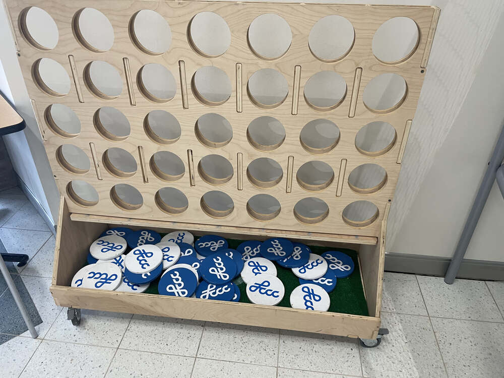
He suggested mimicking this design and using the holes where the game pieces would normally go as a place to feature the lithophanes. This seemed much more promising than my original design. It was structurally sound and had a reasonable approach for the lithophane installation.
So, I started to design a sandwich-style structure for the lithophanes inspired by this design:
However, I noticed that this design required both a front and back piece of wood, as well as materials on the side for the feet.
 I became concerned about how much plywood I would need to use for the design. I also really wanted to find a way to include a curved element to my design. I realized that for my purposes, I could just affix the lithophanes to wood with screws on the back in order to use less plywood. Next, I started thinking about how to incorporate the curve I desired.
Kerf Bending Design in Fusion
After I decided to work with only a front piece of would and to adhere the lithophanes directly to the wood from behind, the first curved design I experimented with involved kerf bending. I knew I wanted to keep the area where we were going to affix the lithophanes flat, and that I wanted the curved feature mimicking the original ArtiFACT lithophanes that would help the piece stand alone. Kerf bending – in which equidistant lines are cut in a piece of plywood to enable controlled bending of plywood – seemed like an ideal approach.
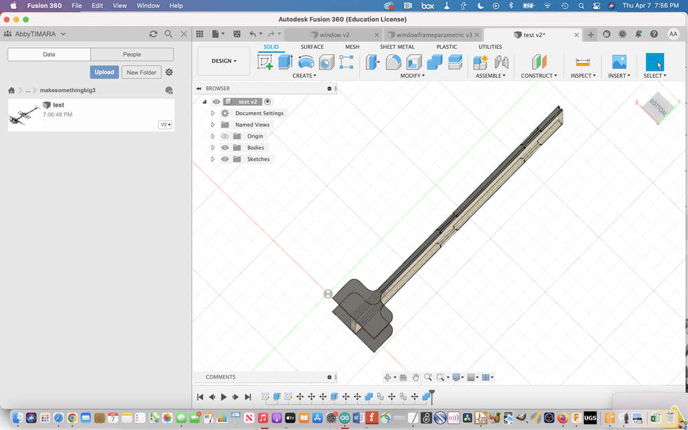
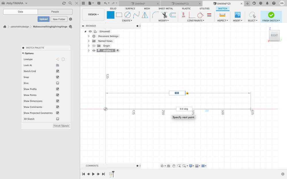
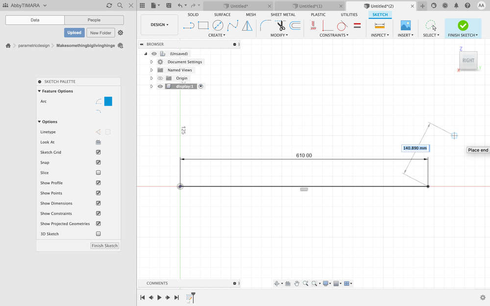
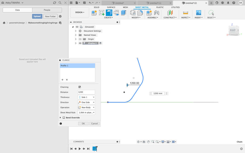
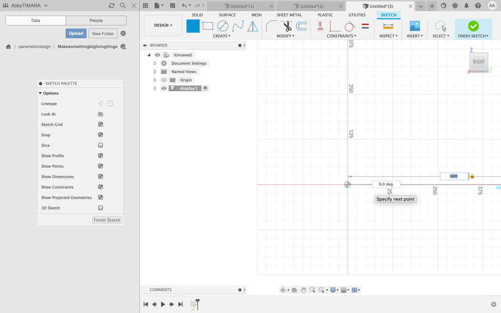
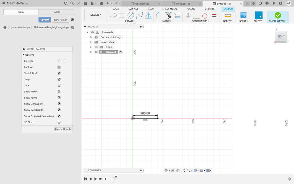
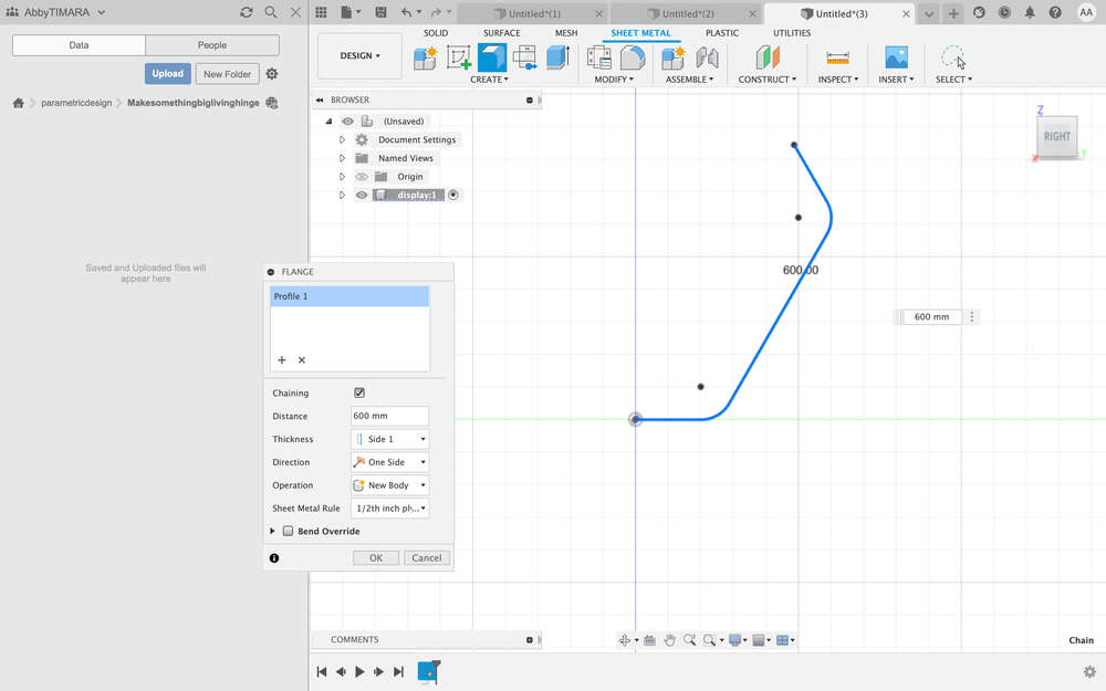
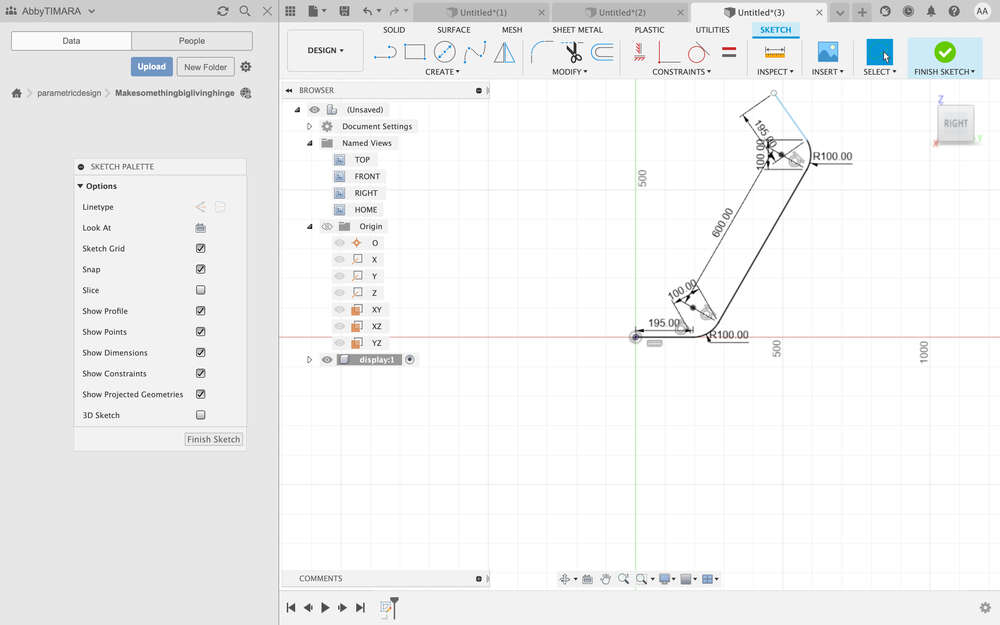
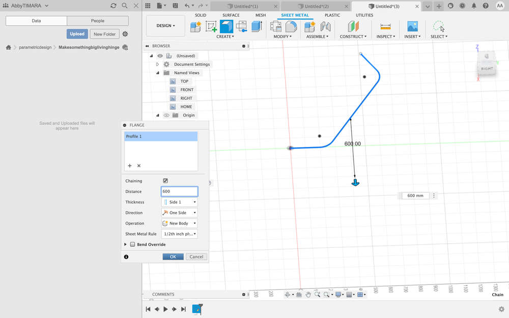
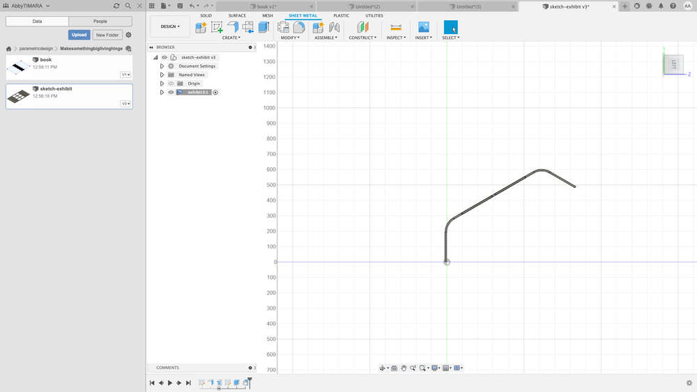
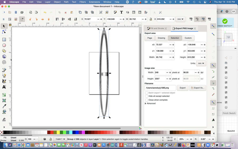
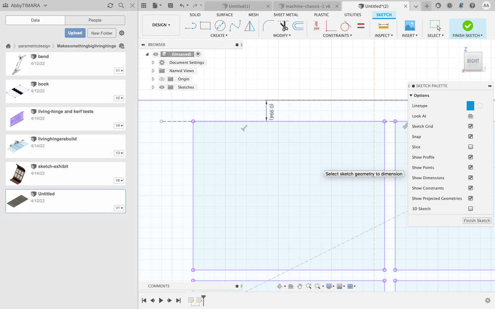
I began by creating a line of 610 mm:
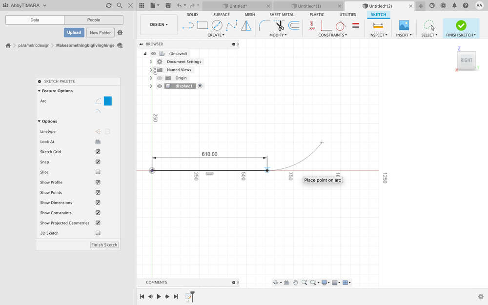
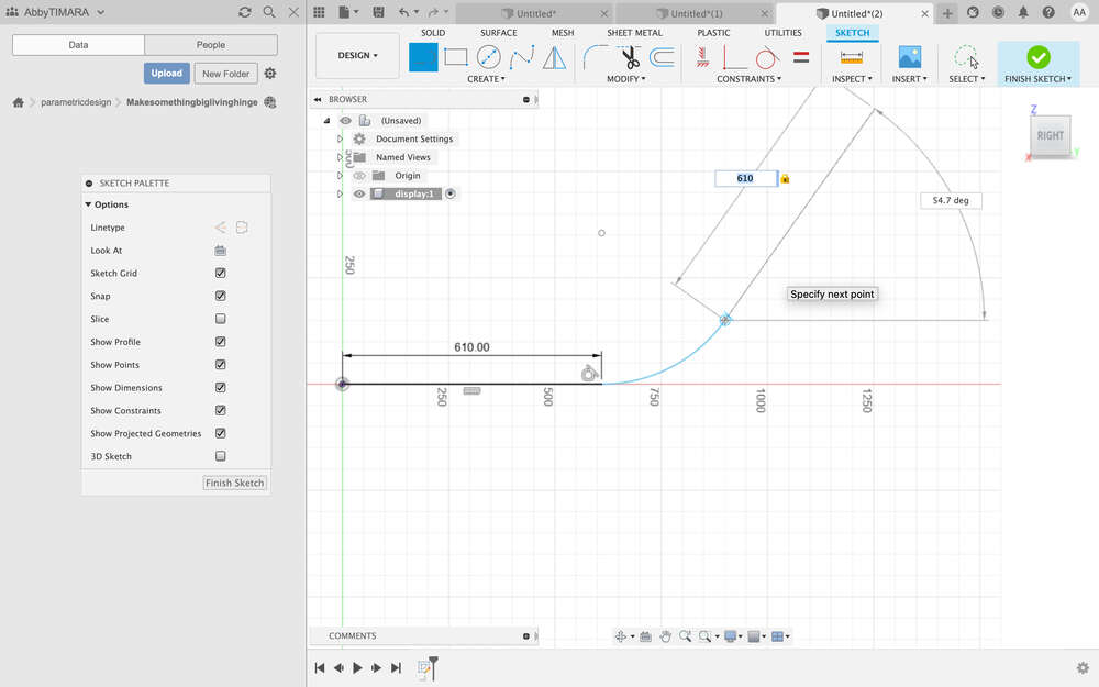
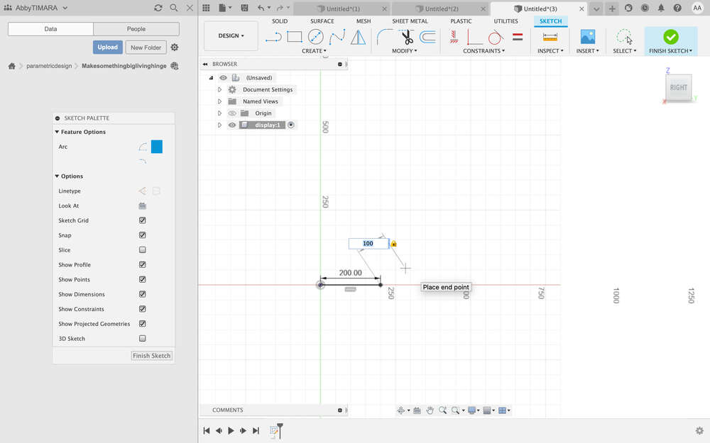
I then created a curve attached to the original line, first by setting the angle of the curve:
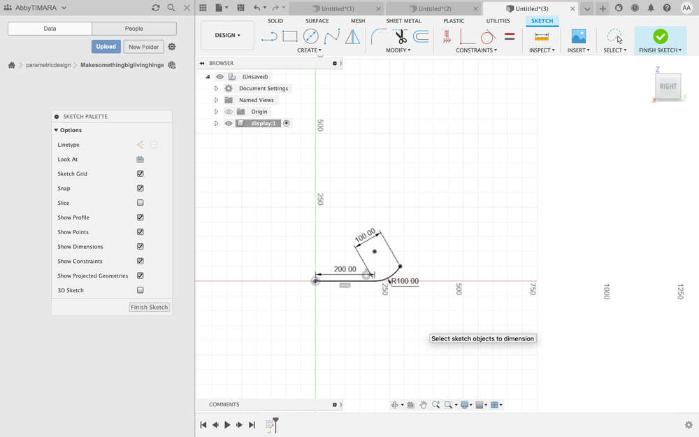
And then finalizing its location:
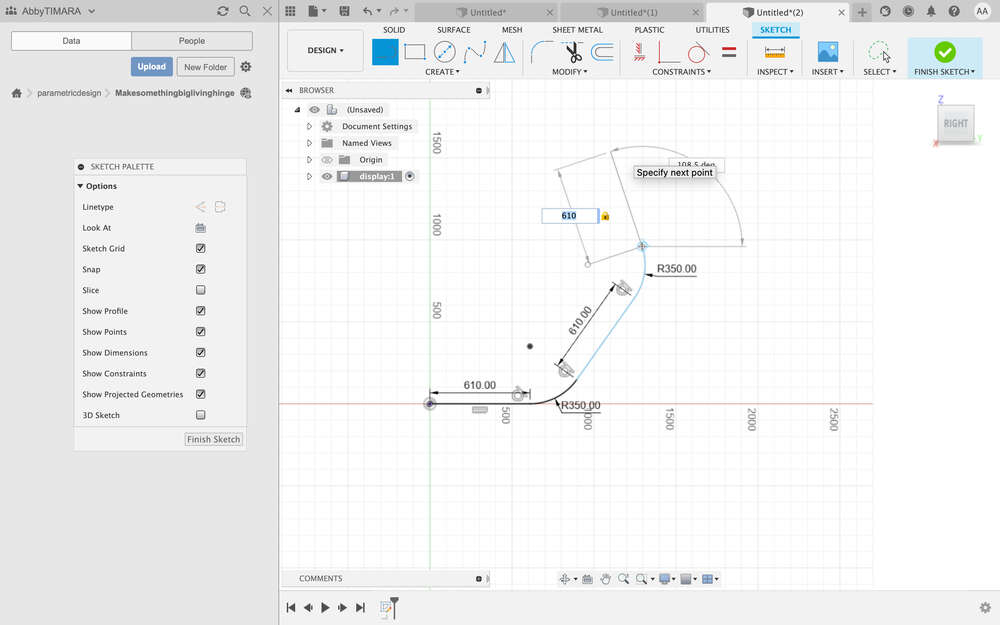
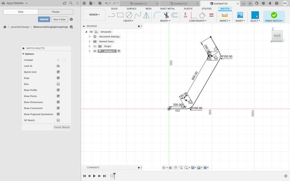
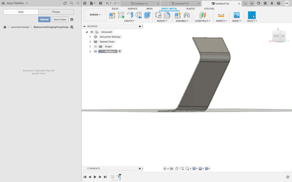
I added another line extruding from the curve:
And then I added another curve and line to create a center segment with two flaps on either side:
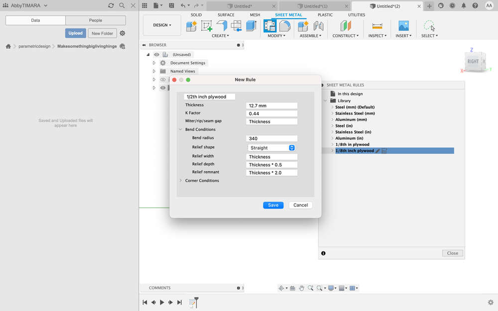
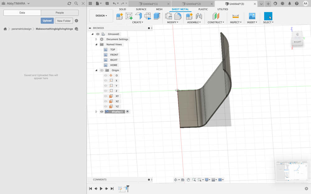
I set the material type:
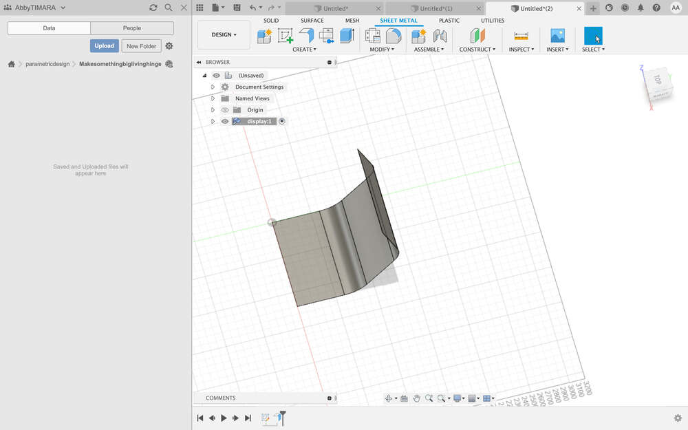
And extruded the lines to create a solid sheet:
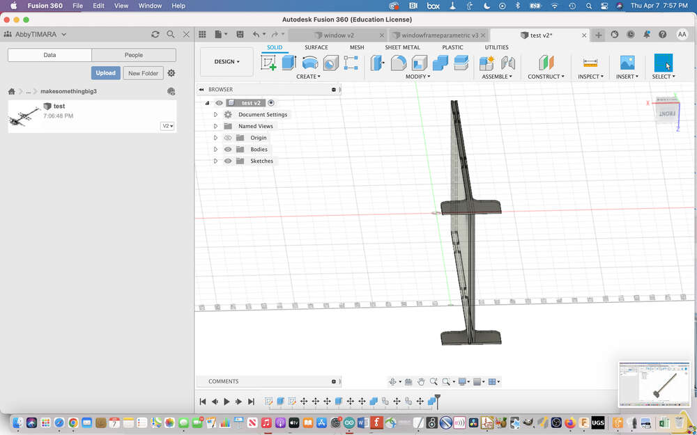
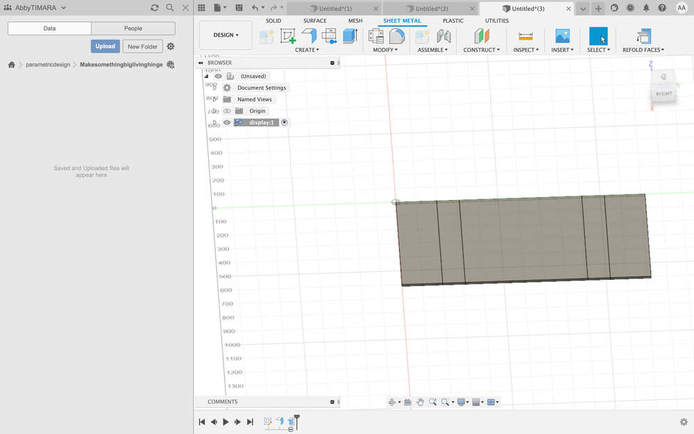
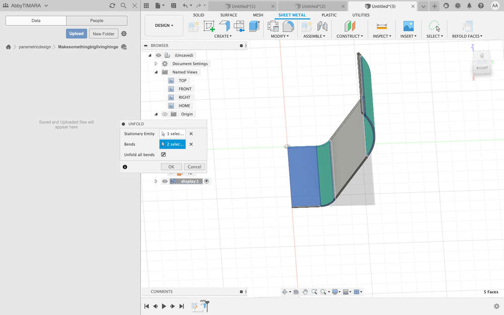
I navigated to the sheet metal workspace:
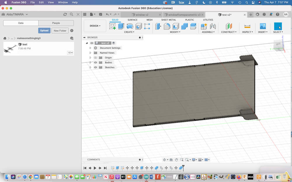
And used the unfold command, choosing which element of the design would remain stationary:
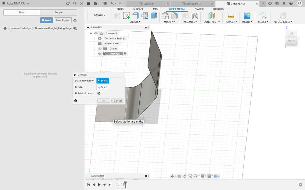
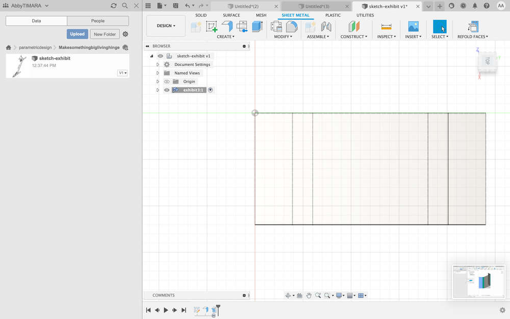
Here you can see the design laid out flat:
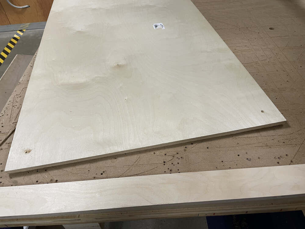
At this point, I realized that I wanted to tweak my design a bit before proceeding due to some logistical constraints. The shopbot I was using at Think[box] has a bed that is 8 ft x 4 ft. I wanted to use as much of this bed as possible so that the final design would be a large, human-scaled exhibit. However, my car is not large enough to transport an 8x4 sheet of plywood! I was able to get by bringing smaller cuts of plywood to cut and also occasionally purchasing an 8x4 sheet onsite at Think[box]. Of course, I had to design the final structure in segments to be assembled later in order to account for transportation.
As I experimented with the next design iteration, I kept the ShopBot dimensions and my car’s dimensions in mind. I also worked to create a larger space to feature the lithophanes, which involved tweaking the proportions of the overall dseign. I followed the same process as before. You can see the new proportions in the images of the design process of the new iteration, below:
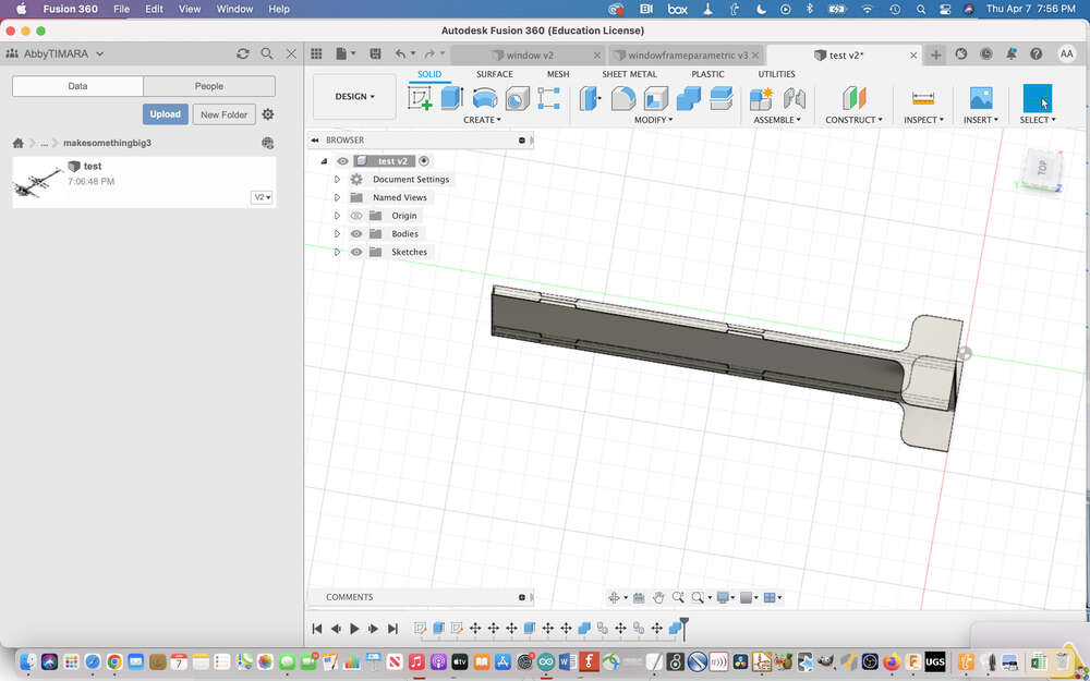
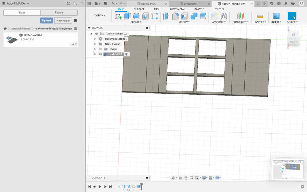
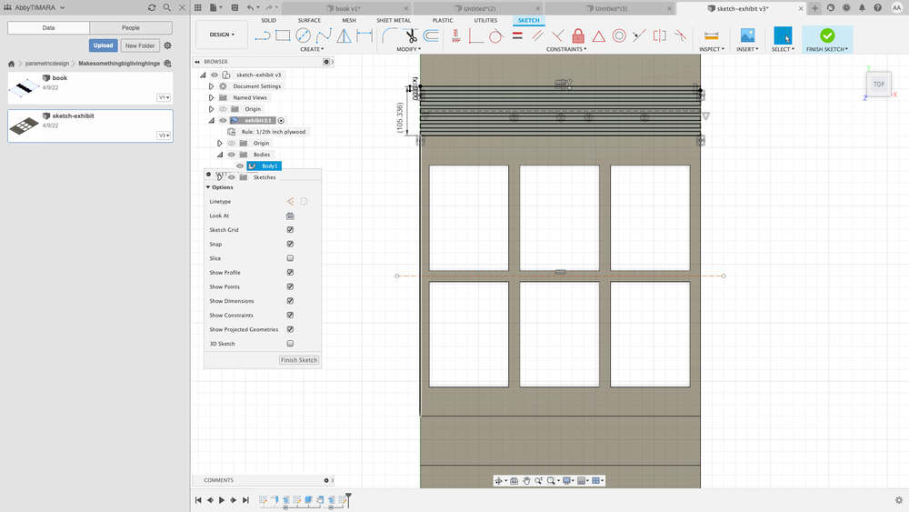
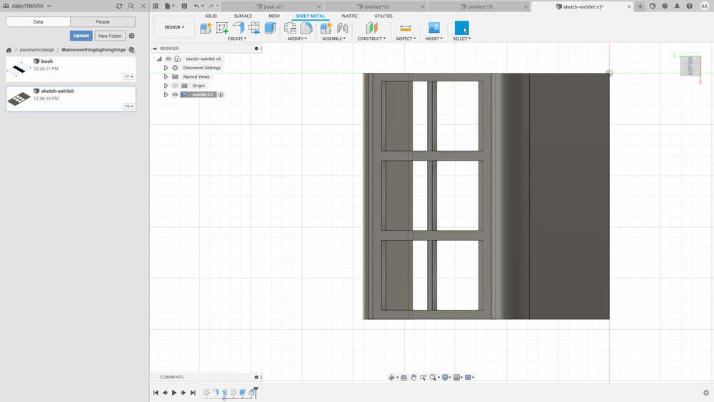
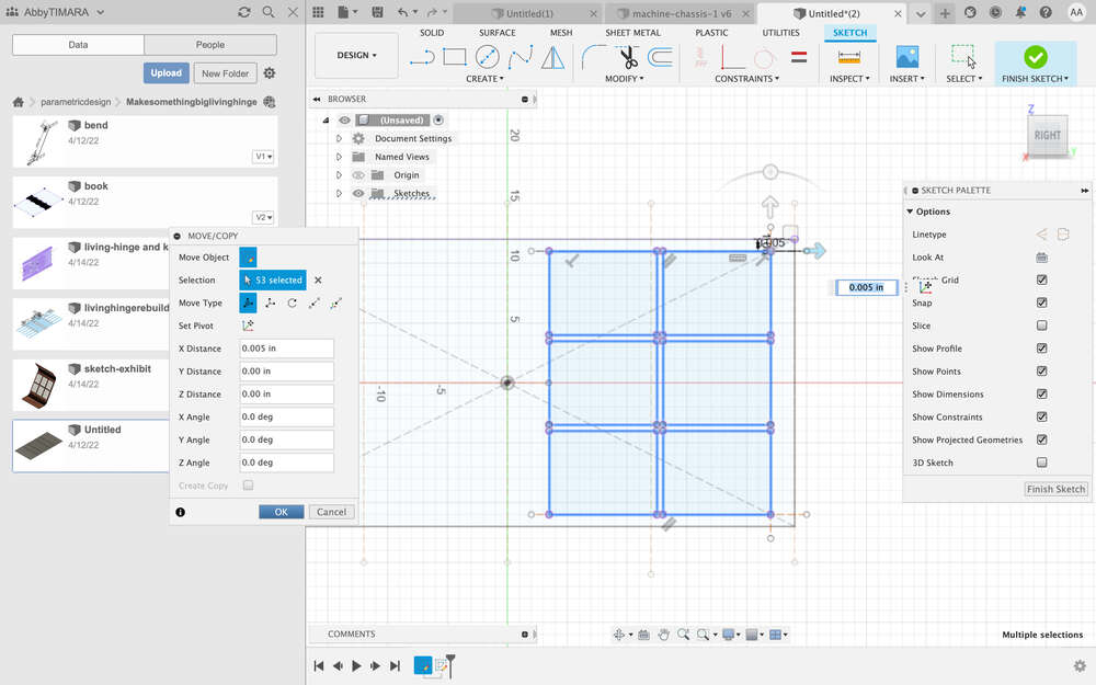
After I was generally happy with the design, I began work on the individual window panes that would house the lithophanes. These had to be just smaller than the lithophanes themselves and the space between the panes needed to leave room for the borders of the lithophanes and for brackets to hold them in place:
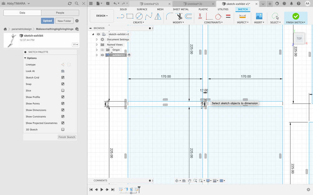
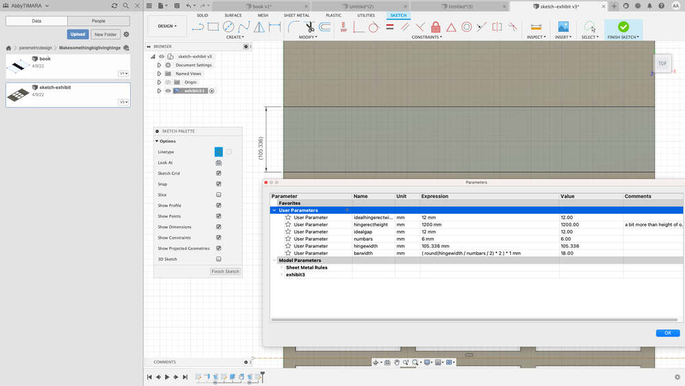
I set the dimensions and constraints:
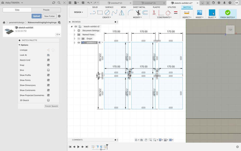
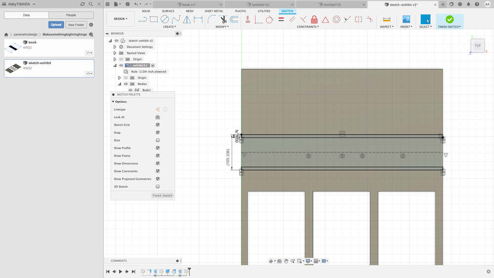
And then moved the sketch into place atop the existing design:
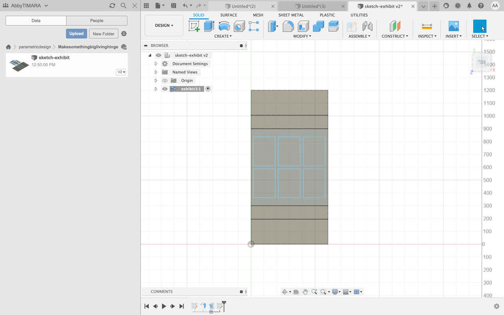
I extruded the window pane sketch through the solid object I had previously created to make the holes where the lithopanes would be secured:
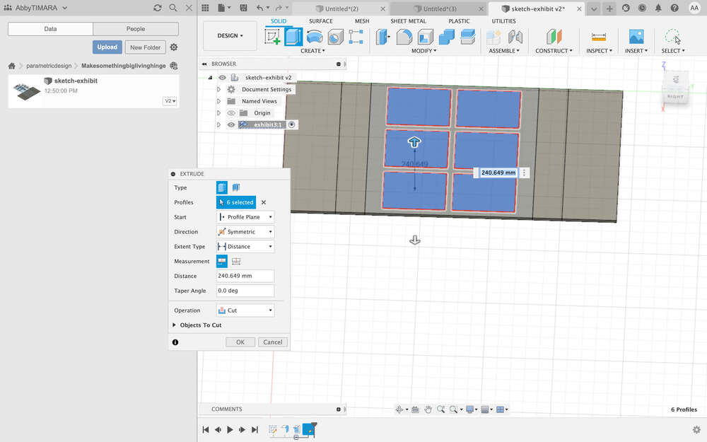
Here you can see the flat solid with the window pane areas removed:
Next, I began working on the kerf bend. I checked the dimension of the area I wanted to bend:
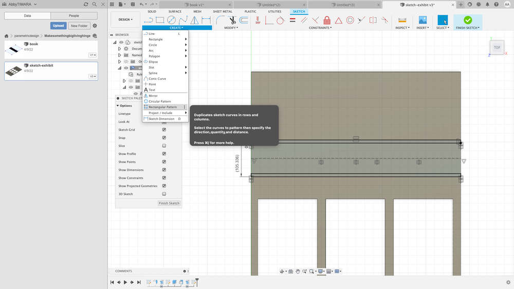
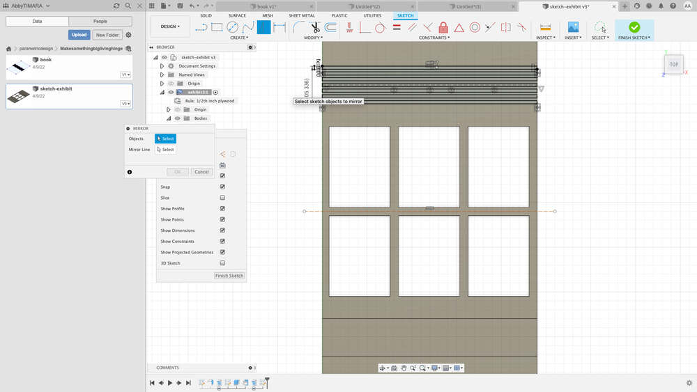
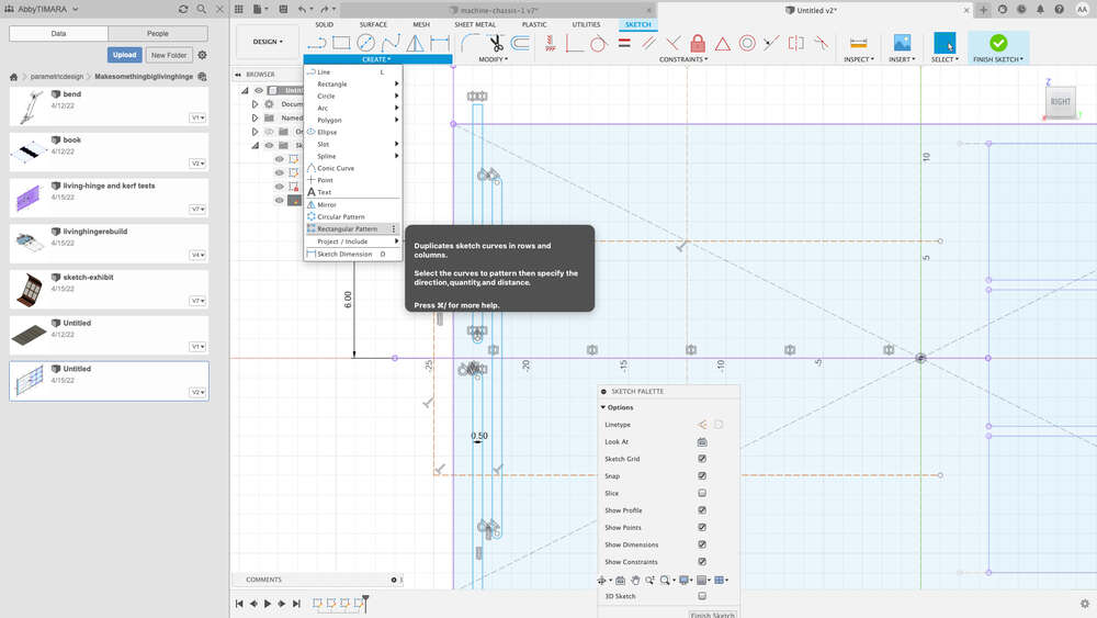
And then I added a construction line in the center of the area and began creating rectangles symmetrically on either side of the construction line:
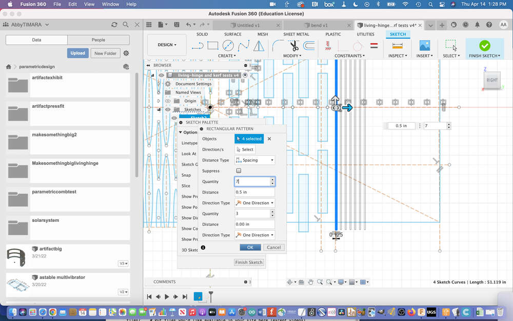
Next I chose a side from which I would create a rectangular pattern:
I set the number of repetitions and the distance between repetitions:
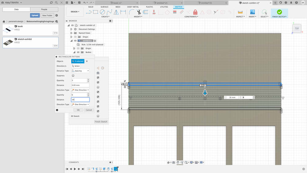
…in order to generate the desired pattern:
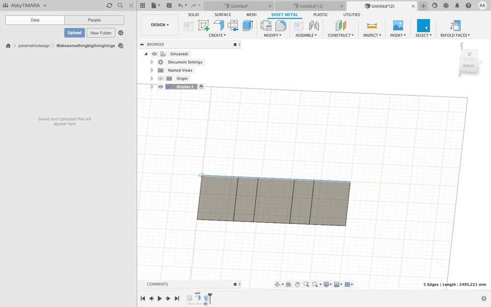
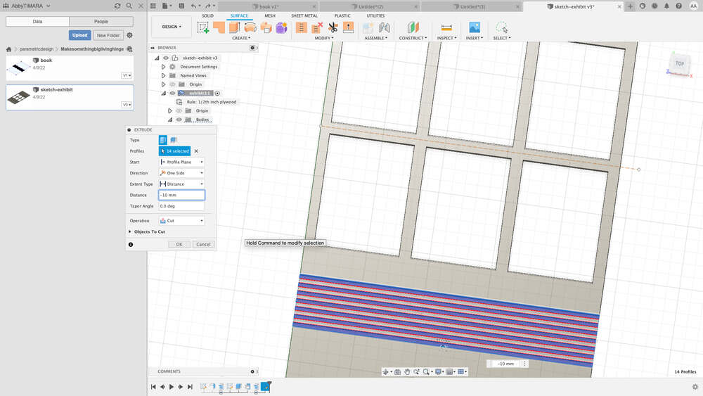
Here I extruded every other rectangle to cut troughs into the display:
And here you can see how I was hoping the display might come together and bend:
Front view:
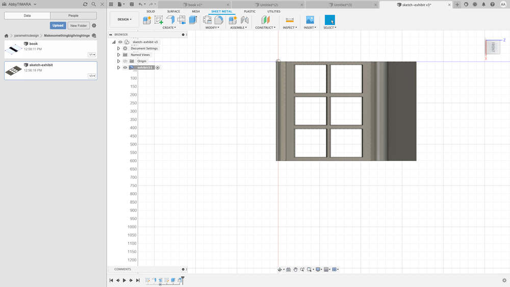
Top view:
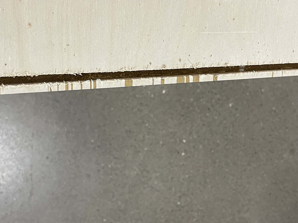
I should pause to point out that I naively went into this process with no concrete idea of what dimensions I would be need in order to successfully create a bend in the plywood. There are online calculators as well as tutorials. But I didn’t dig too deep into these and other resources. Instead, I just crossed my fingers and got going. Spoiler alert: it failed pretty spectacularly, though I did not actually try steaming or gluing the wood to assist witwh the bend. When I saw how rigid the wood was, I felt pretty confident I would not be able to do anything to fix it. All that said, I needed to go through the fabrication process to come to this conclusion. Below, I walk through next steps in this fabrication process, including using CAM software to generate the toolpath and actually routing the plywood on the ShopBot.
CAM Toolpath
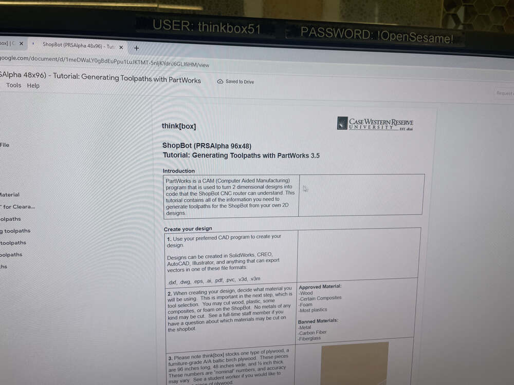
Designing your file in Fusion is only the first of several steps one must follow in order to generate the G-Code file for the ShopBot. After you design your file, you need to import it into a tool path generator like Partworks or Aspire. Given the physical properties and constraints of the machine, Partworks, Aspire, and other CAM software help translate a raw version of your project into a file that contains detailed, step-by-step instructions for the machine that takes into account the physical properties of the materials and tools you are using in order to fabricate your design.
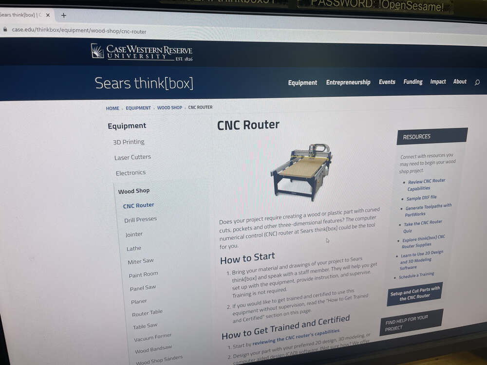
Thankfully, Think[box] has a lot of really useful tutorials that both I and the student workers helping me referred back to quite a bit throughout this process. I started out by looking up the CNC ShopBot at the Think[box] to get to the relevant documentation (with search results):

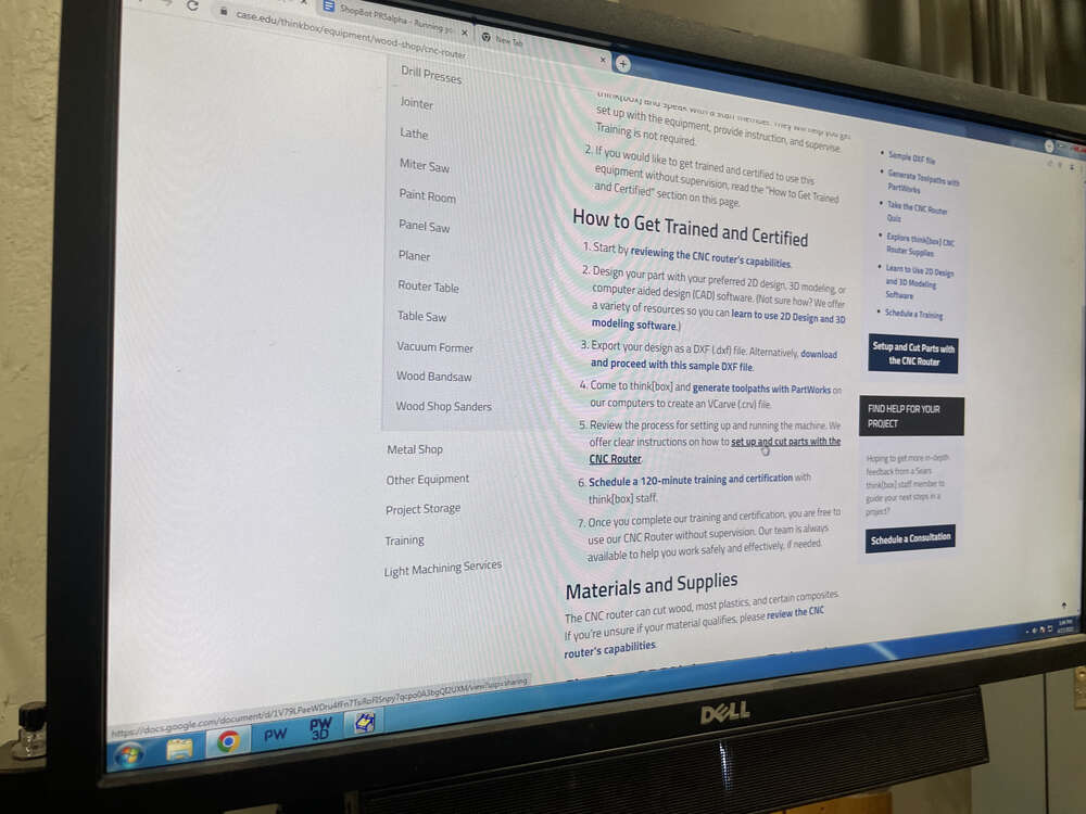
Next, we looked at the CNC router documentation page:
From there, we were able to find the link for step-by-step documentation of CNC router training process:
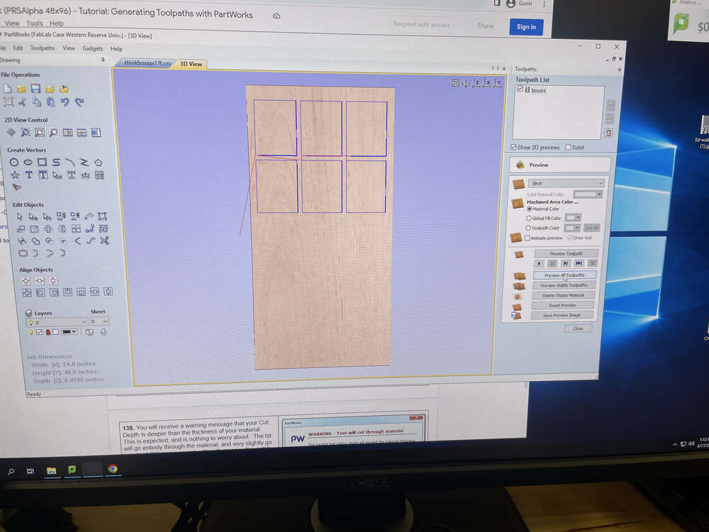
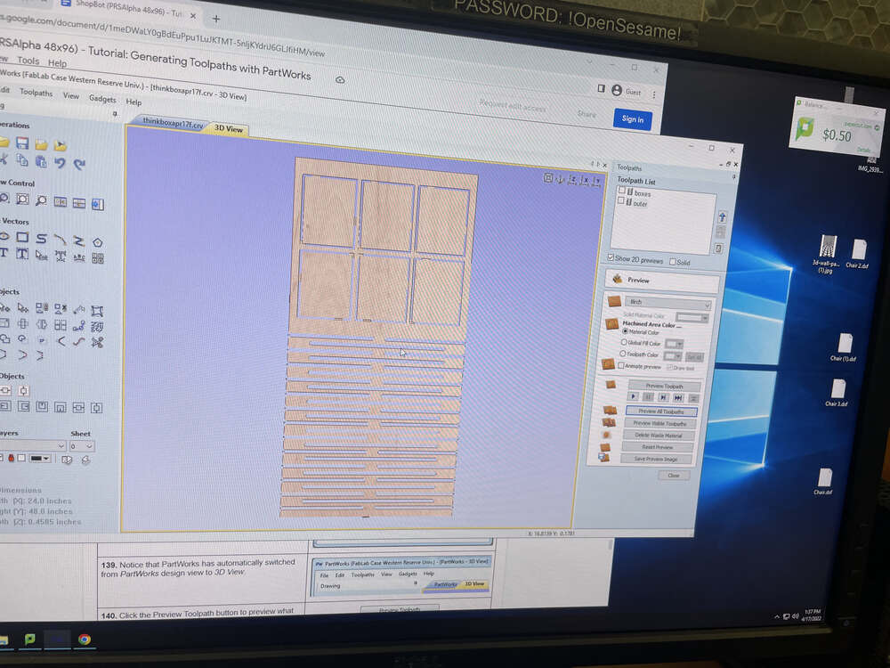
And here we pulled up the tutorial for generating toolpaths in Partworks:
In case you want to dig deeper yourself, here is the direct link to the Thinkbox CNC training document.
At LCCC, we use Aspire, which is a bit different than Partworks. After I familiarized myself with Partwork’s user interface, I began by specifying details about the materials I was cutting and the tools I was using to make the cuts. For example, I entered the dimensions of my plywood, including the precise thickness of my material (measured with calipers) so that the machine would know how deep it should cut.
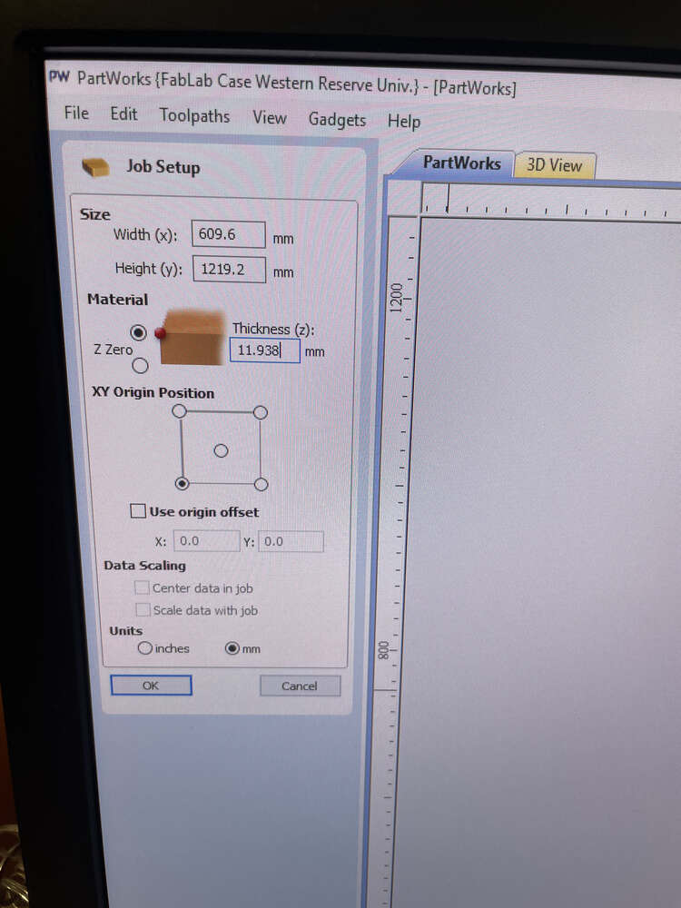
Since this measurement needs to be precise, ideally take measurements in several locations on your material to determine the most accurate dimension for the material thickness.
After setting the material properties, it was time to import the design file, which in this case, was a DXF file I designed in Fusion 360. When you first import your design into Partworks, you will need to move it into place:
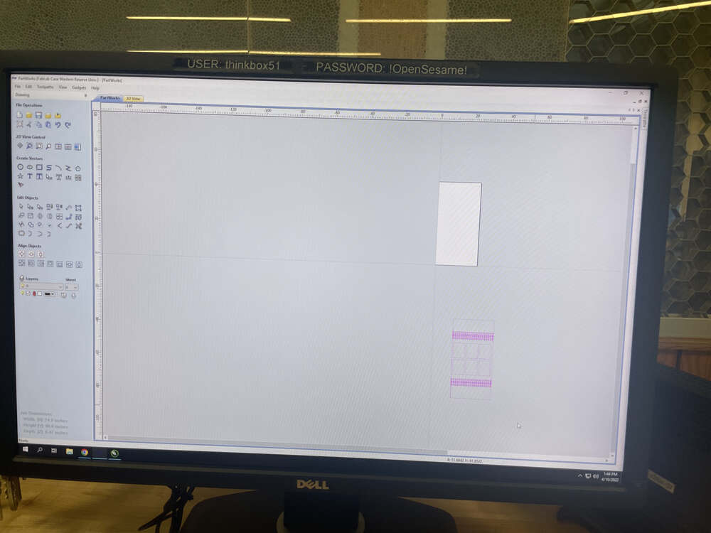
Align it closely with the material dimensions you specified in your workspace:
Note in case you are following along step-by-step: as you will see shortly, as I pursued the next several steps of generating my CAM toolpaths, I learned that now would have been a good time to check that all my vectors were closed.
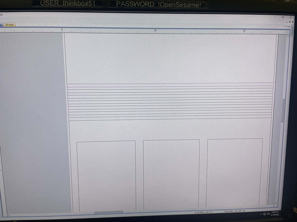
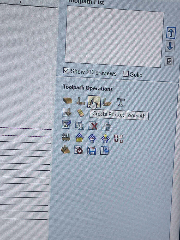
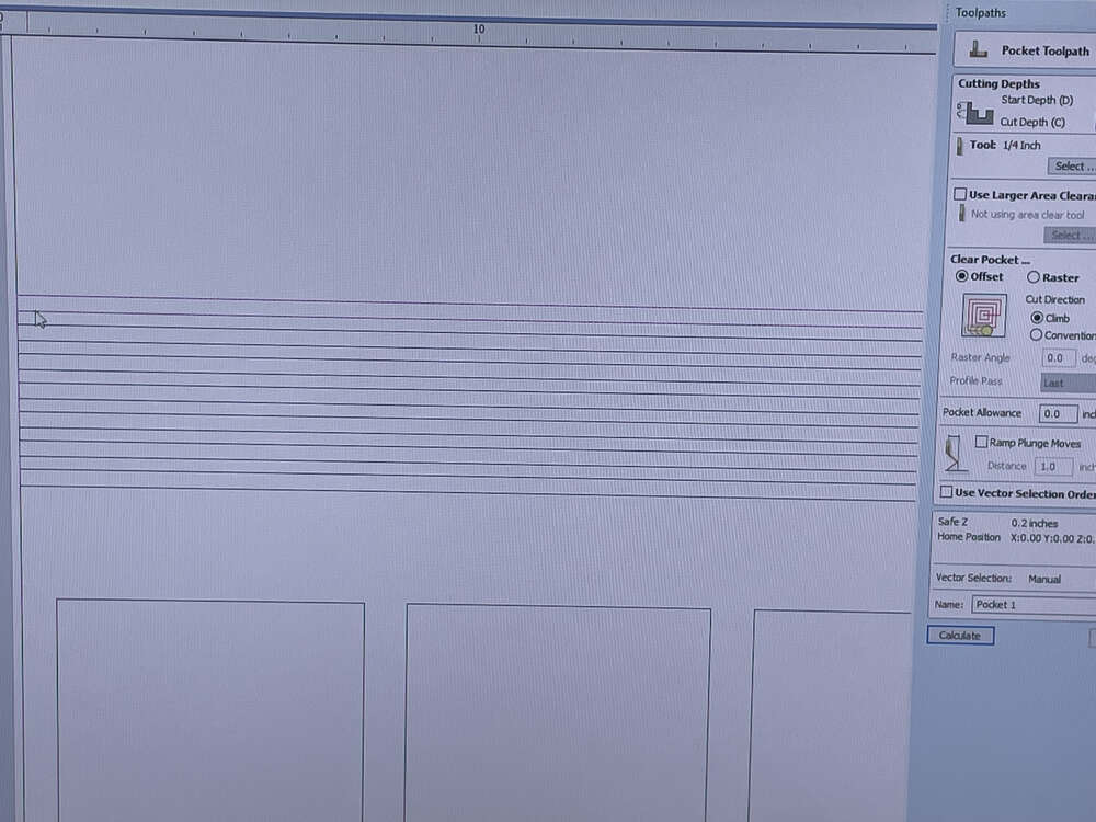
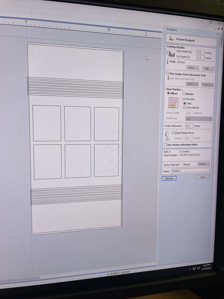
Next, I generated the type of toolpath I wanted to use for the Kerf bending section. In this case, I chose the pocket toolpath to cut the Kerf bending section:
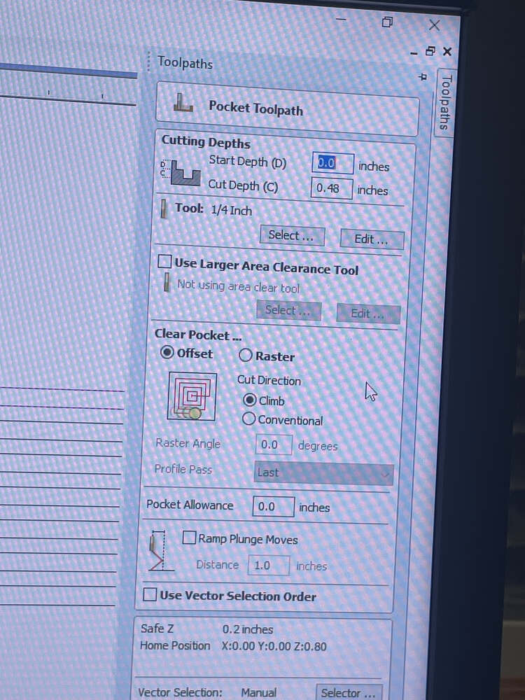
 The start depth should be zero inches:
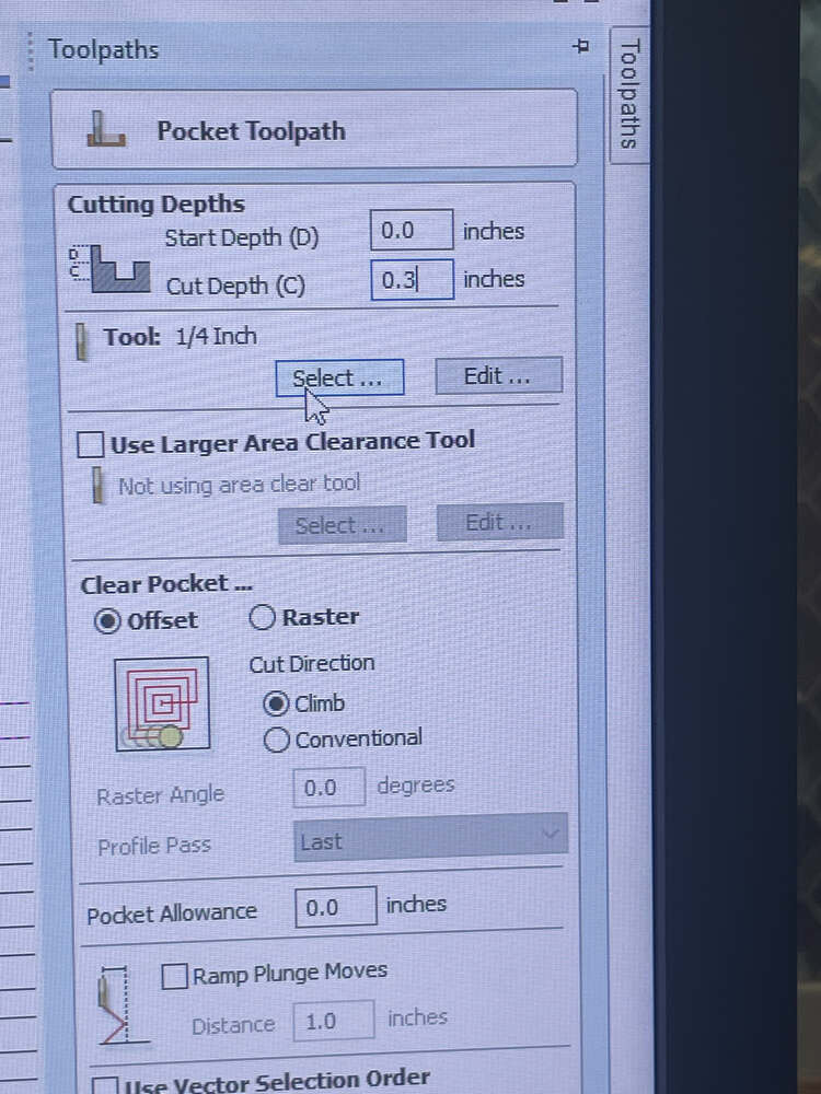
 The cut depth depends on the thickness of your material. Based on the measurements I had taken, I chose 0.3 inches for my cut depth:
Here is where the trouble started: when I tried to apply the pocket toolpath to the kerf bending section of this design, I discovered that I had open vectors! Partworks and other CAM toolpath software do not like any open vectors. I think the main concern is that this could impact the route that the machine assigns to make its cuts and also the final outcome.
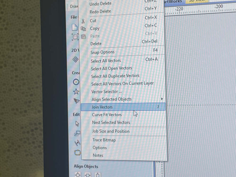
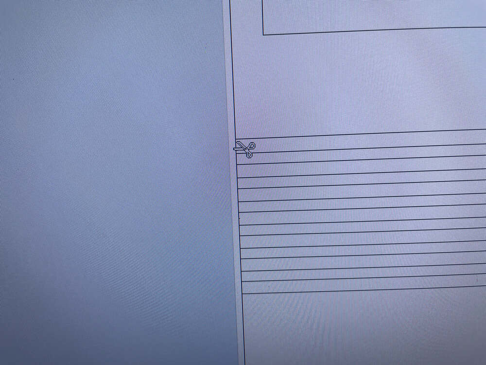
To fix the open vectors, I tried several things that did not work. I began by selecting all open vectors:
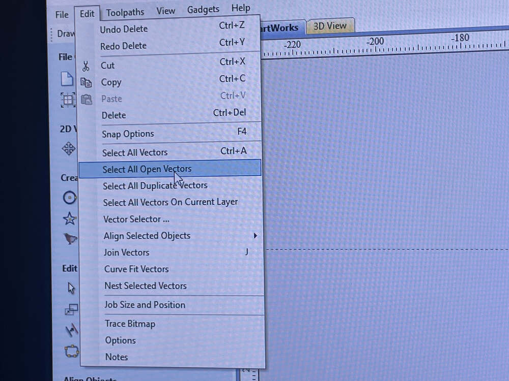
And tried to join the vectors but this did not solve the error message.
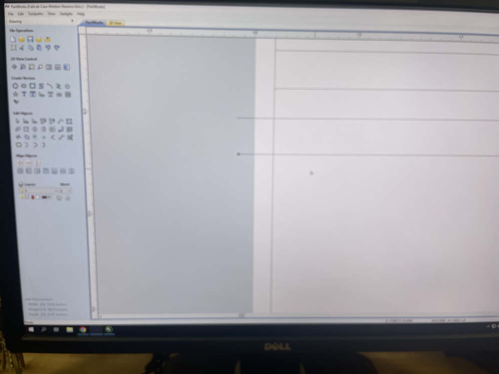
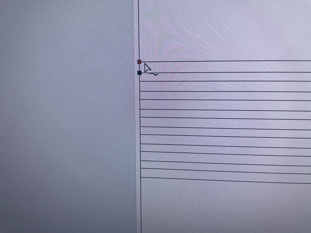
I then tried extending the lines beyond the edges:
 And cutting them back again:
 But this also did not close the open vectors:
 In fact, it seemed like there were multiple overlapping layers, which might have been part of the problem. And ultimately ended up dragging connected points:
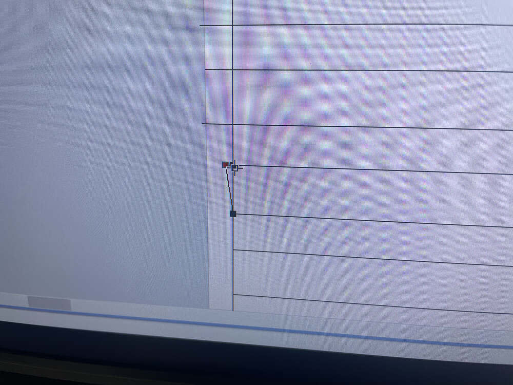 And moving them beyond the lines:
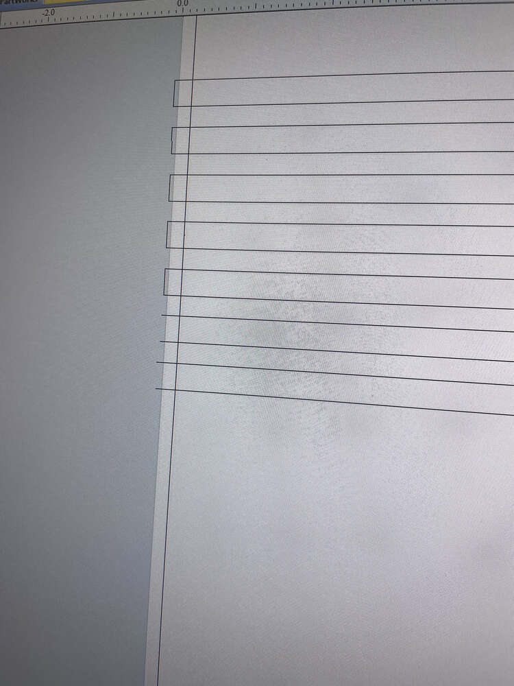 Taking care to do so on either side of the design:
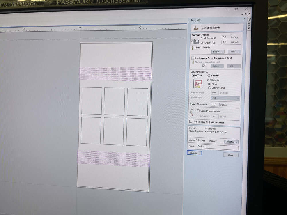
 I was able to close vectors on these extended sections and assign the pocket toolpath. Given the size of the machine and the scale of the project, we were not worried about the toolpaths being a bit longer than the chosen material.
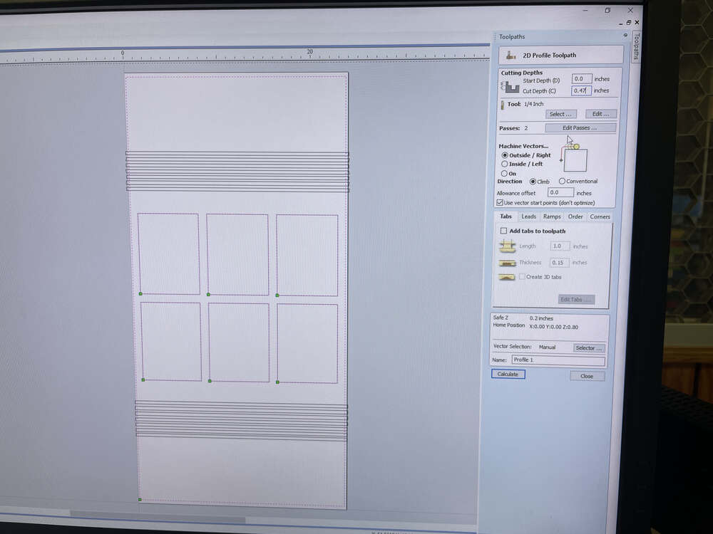
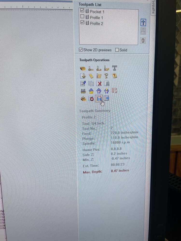
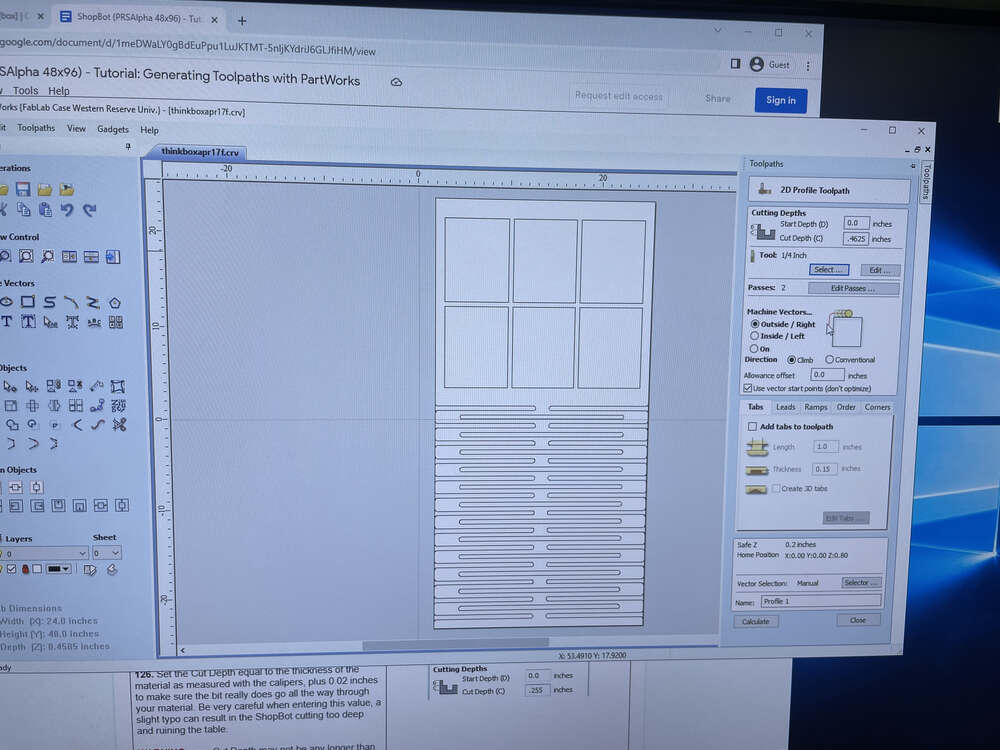
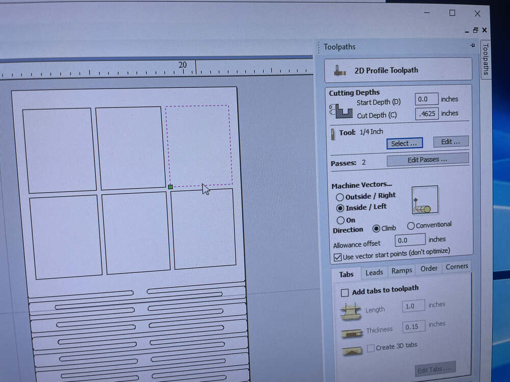
 Next, I used the 2D profile tool to cut the windows. In the tool dialog, I assigned the cut depth to 0.47 inches to cut through all of the material while limiting the impact on the spoil board. I set the tool type to 1/4 inch and chose whether the cut should happen on the inside or outside. Contrary to the picture, ‘inside/left’ is the best option here because this will make sure that the material that is cut is waste material rather than part of the desired design. This dialog also provides space to access the ‘add tabs’ dialog feature for safety and a space to name the particular toolpath generated.
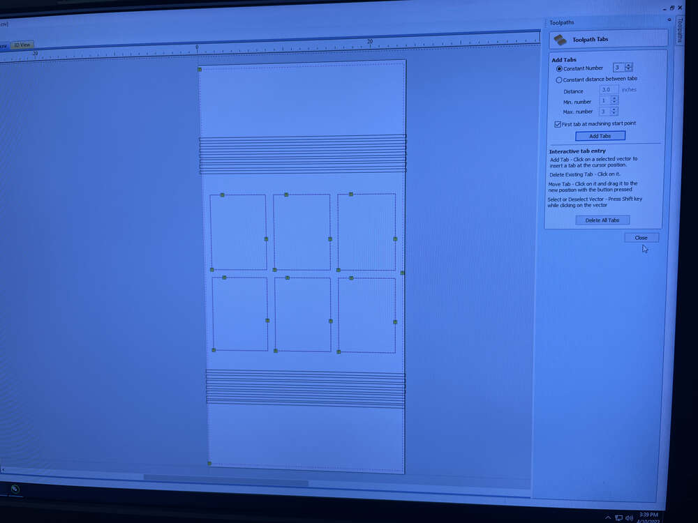
 If you need to add tabs after you select this feature you can specify details about the tabs you would like to add:
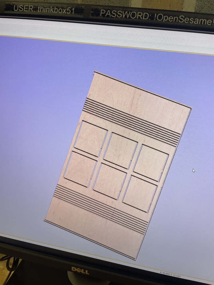
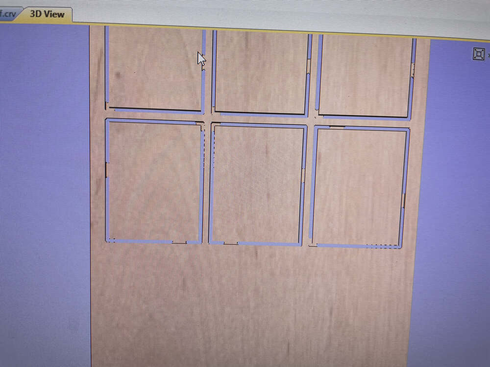
 Here is a rendering of the toolpaths:
 If you look closely, you can see the tabs in this rendering as well:
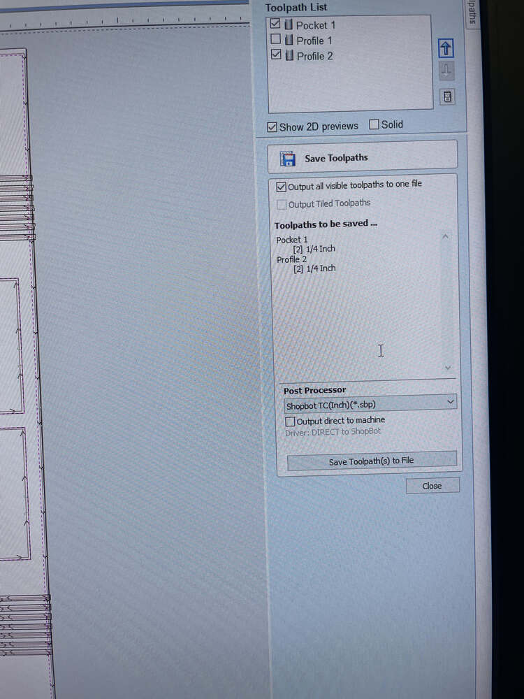
If you are happy with the CAM toolpaths generated, you should save the toolpath:
 Saving toolpath to file:
Kerf Bending Fabrication
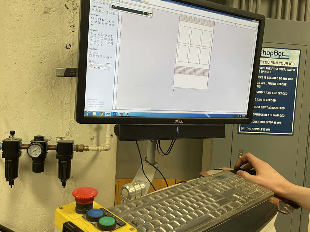
When it came time to fabricate the design, first, we moved the computer by the Shopbot. We ended up re-opening the design in Partworks to double check the orientation and exported the file again before opening it in the Shopbot software.
Opening the project in Partworks
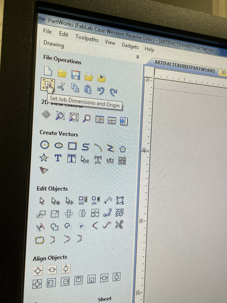
 Setting the job dimensions and origin
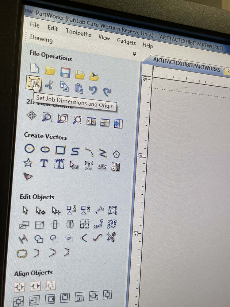 Setting the job dimensions and origin. Note somewhat confusing orientation of Shopbot in the room.
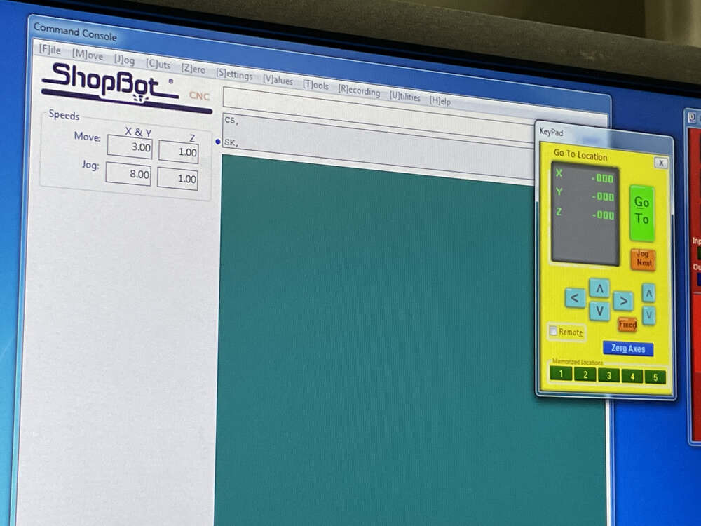
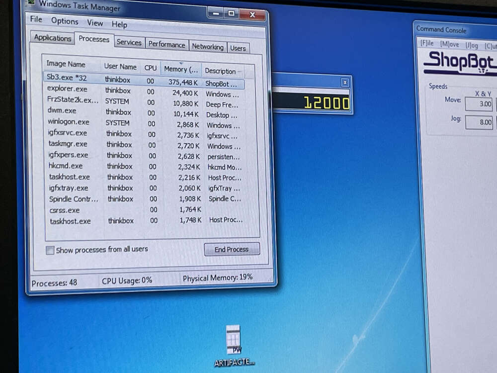
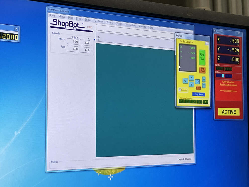
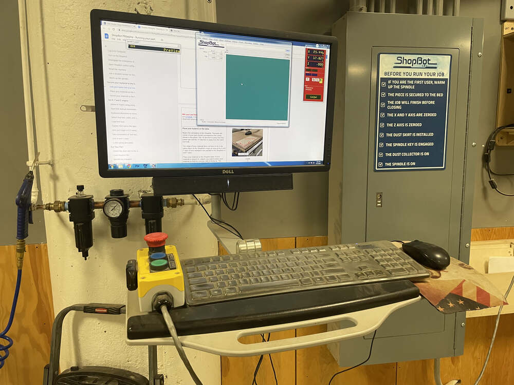
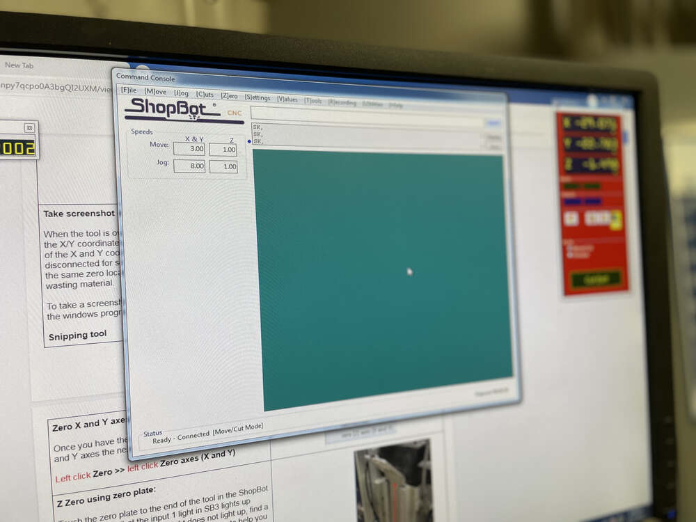
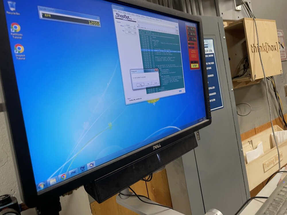
 The ShopBot digital control interface. Notice the yellow window with the toggle controls especially.
 Navigating to the file
 Back to the control interface
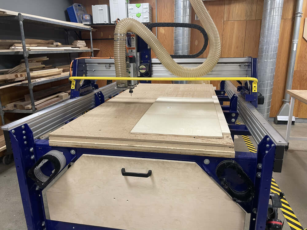
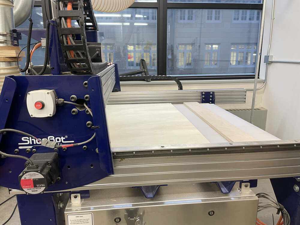
After getting oriented to the ShopBot software, it was time to affix the stock to the spoil board.
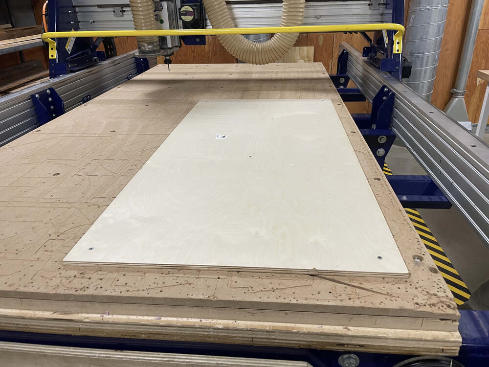
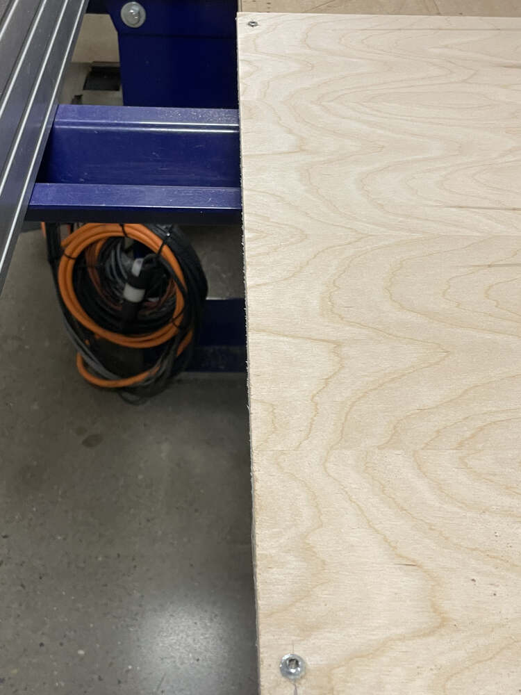
Placing material on the bed and squaring it to the edge
 more squaring
 more squaring
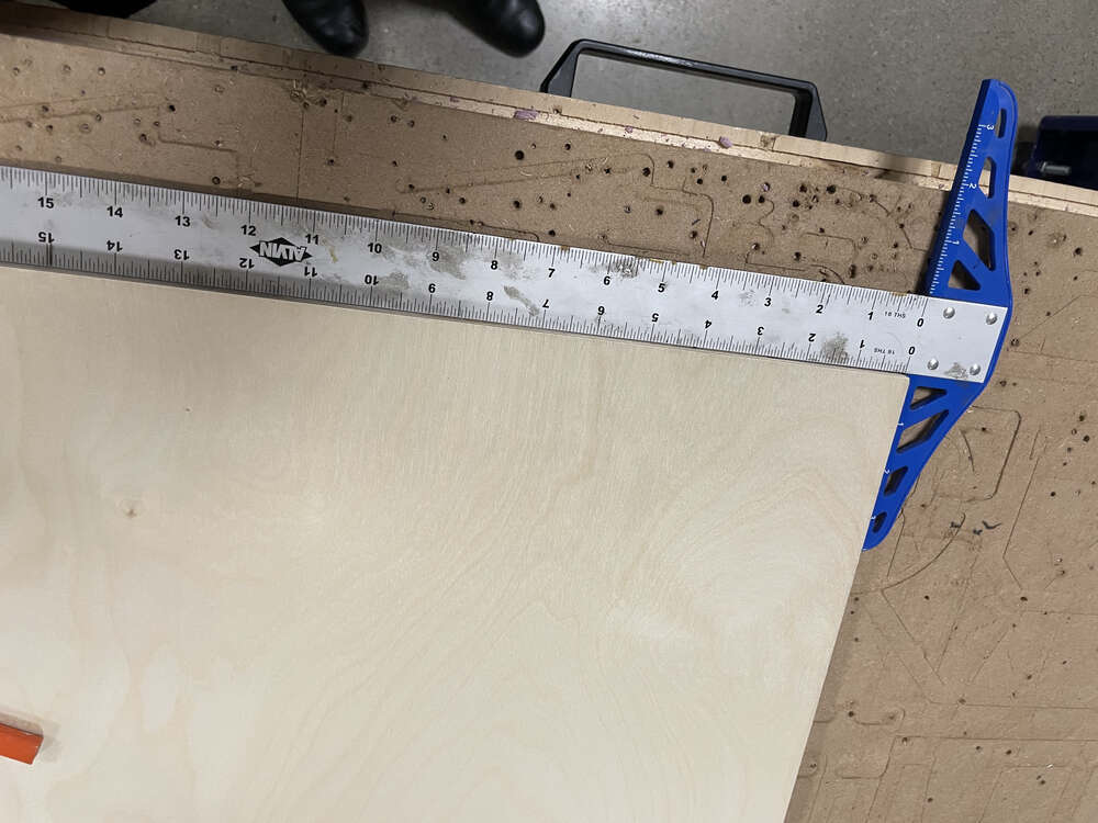
 Measuring location for fastening material to bed
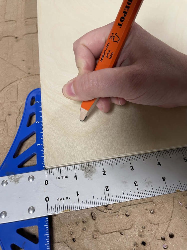
 Marking location for fastening material to bed
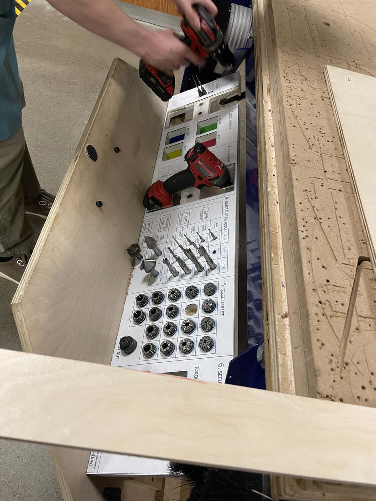
 Getting drill to fasten material – notice the organization of their tools!!
 Pre-drilling holes
 Material affixed to bed
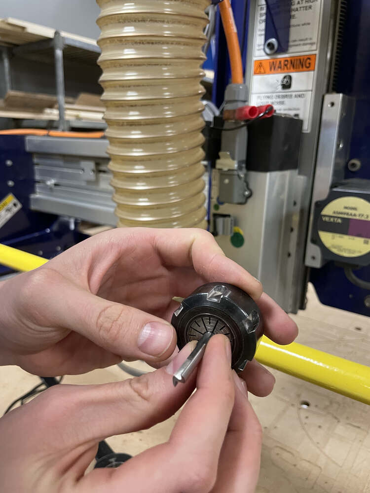
 The 1/4 inch tool we used
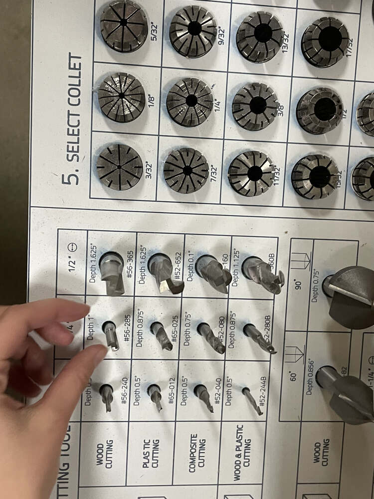
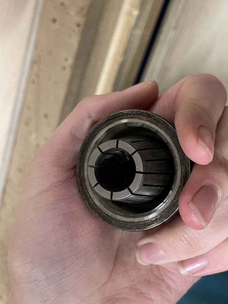
 The collet
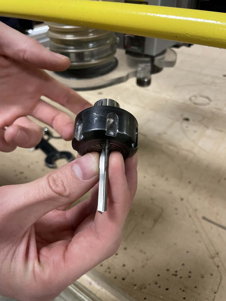
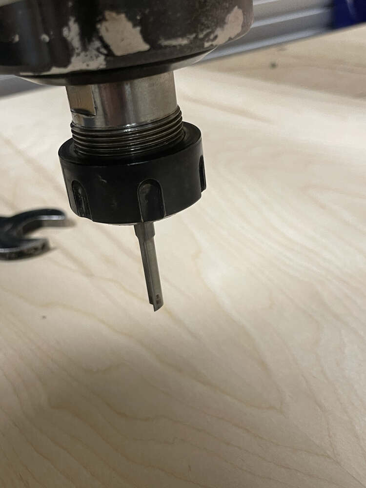
 Putting the 1/4 inch tool with two flutes in the collet
 Keep it flush with the end
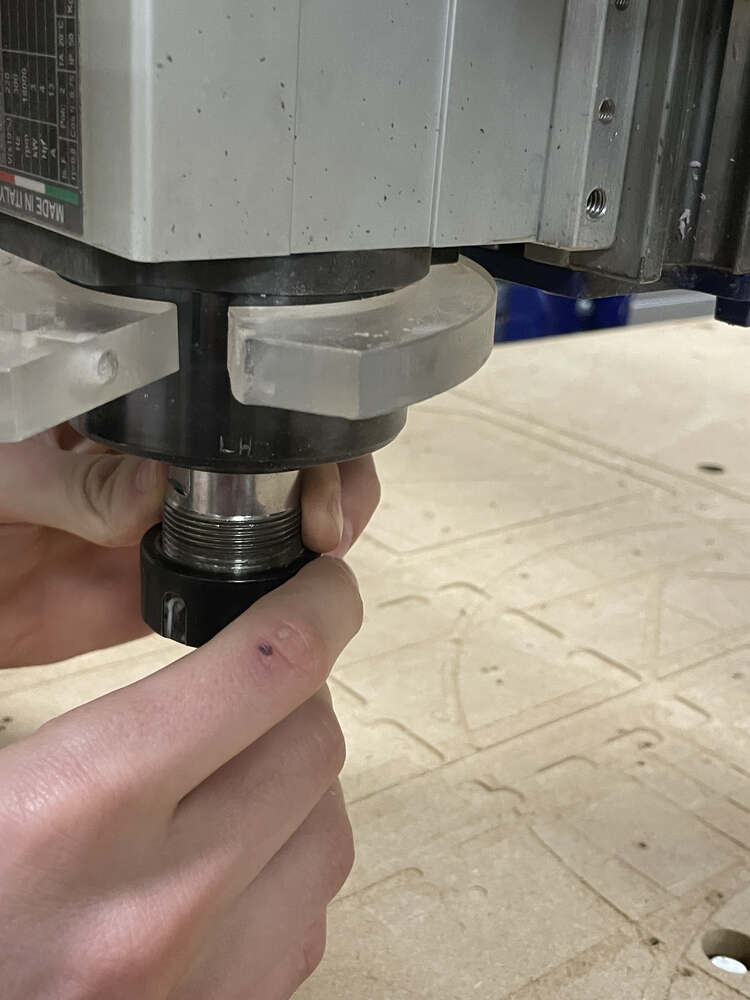
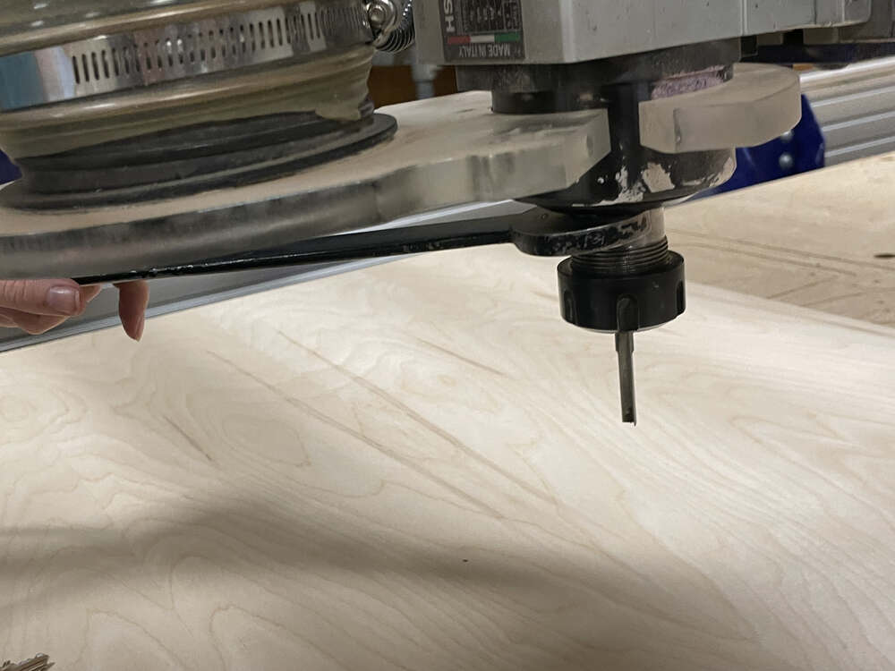
 Affix it back to the spindle, first by hand
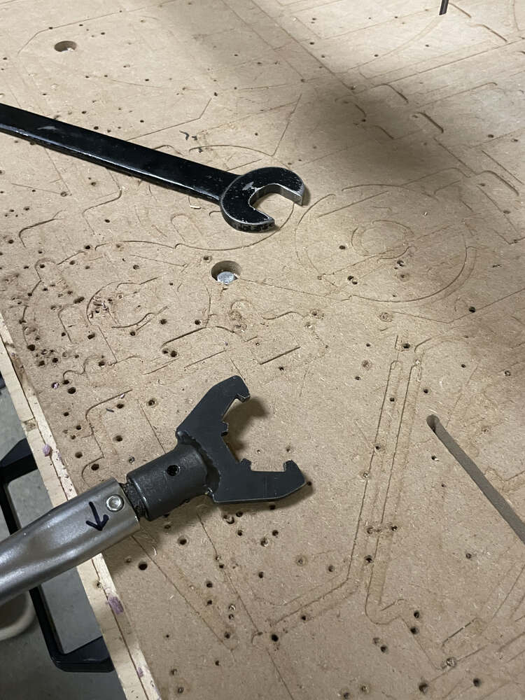
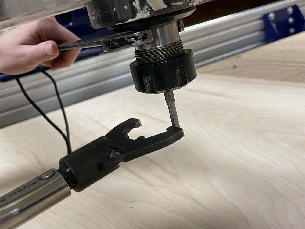
 Then use the special wrenches to tighten it
 The wrenches
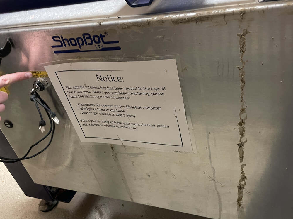
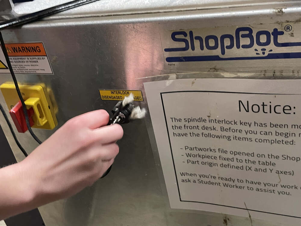
 Safety notice regarding the spindle interlock key
Luckily, there is a metal plate that allows you to automatically zero the z-axis:
Zeroing z axis
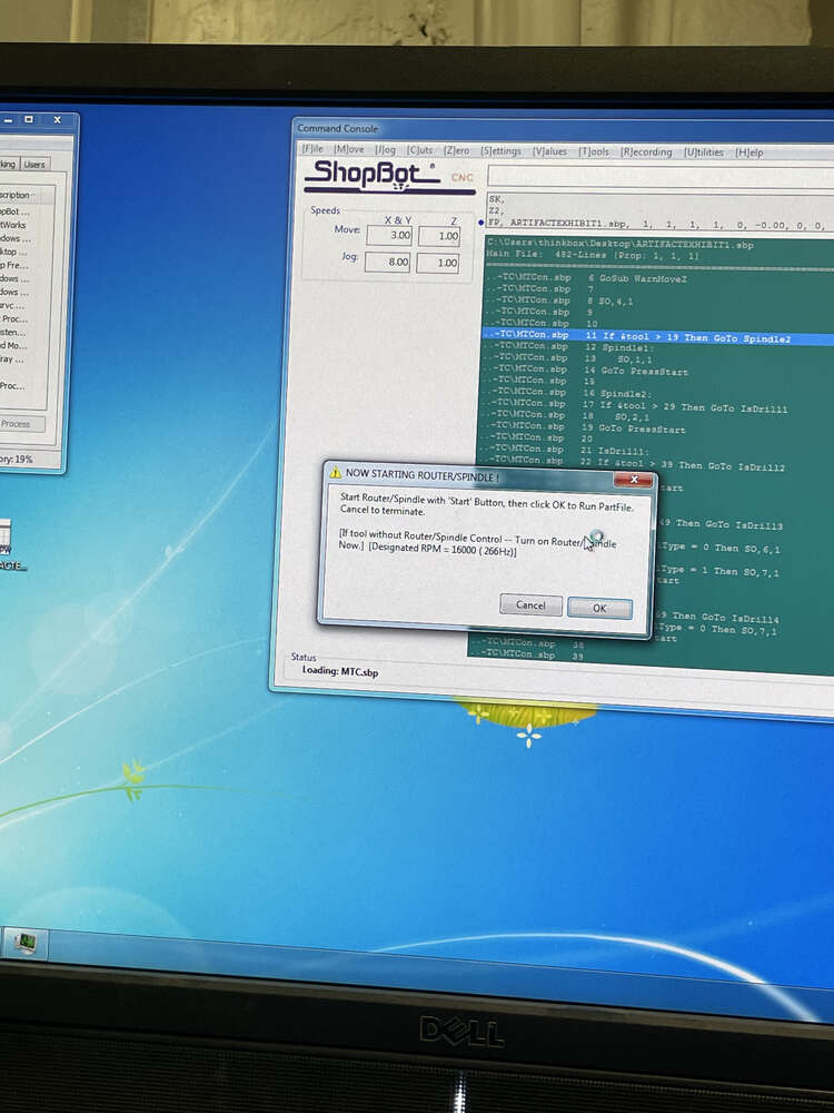
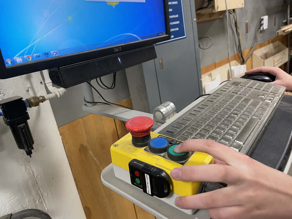
Time to start the machine! Big buttons for a big machine:
 The software sends an alert dialog so you know that it is now starting the spindle
 And it is off! This job went quickly:
 All done!
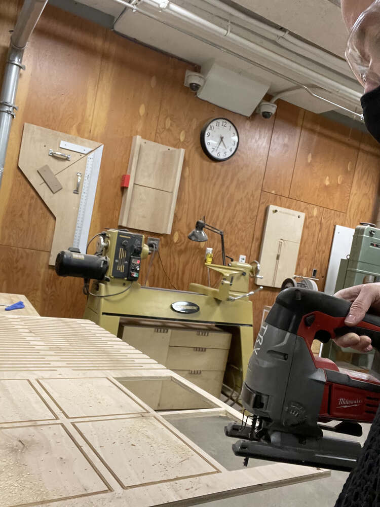
Actually…not quite all done. Next I had to cut out the tabs holding the inner window panes in place by hand with a jigsaw.
I noticed that the machine was a bit rough in cutting the material. I think it was partly due to the stock I used which was not great, but also likely due to the tooling.
By the end of this initial visit, I was able to successfully cut a first prototype. As I mentioned above, after I cut the piece, I realized I didn’t really have any idea how to calculate what parameters would be required to create a kerf bend. Subsequently, I realized that there was an even more significant issue in this design which was that the six panes of glass panes centered in the middle of the 2 x 4 piece of plywood create a portrait style structure, but all of our images are in landscape. For a moment, I was really unsure how to proceed. However, after thinking about it for a while, I realize that I could use two pieces of 2 x 4 plywood and create a hinge in the center which would make the design look even more window like. Given all of the challenges I had with the kerf bend, I went back to LCCC to ask my instructor’s advice, and to look at the living hinge in the lab for some inspiration. I noted the dimensions of the living hinge that he created and did my best to re-create this in fusion.
Final Design
My final design incorporated elements of all of the previous design iterations. I used the window panes to house the lithophanes, though now with a landscape orientation. I was able to incoroprate the curved design using a living hinge. You can see my design process in Fusion, below:
Living Hinge in Fusion
It took a few tries to get a workable living hinge design. First, I experimented with a range of different patterns to try to create a living hinge.
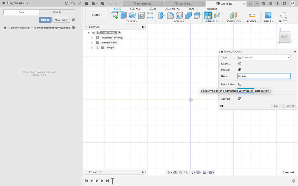
 I created a rectangular workspace and separated it into working sections:
 …and tried some more alternating ovals and rectangles
 But when I tried to export the file and to work with it in fusion, something strange happened and the ovals were incorrectly sized. They were also all on top of each other.
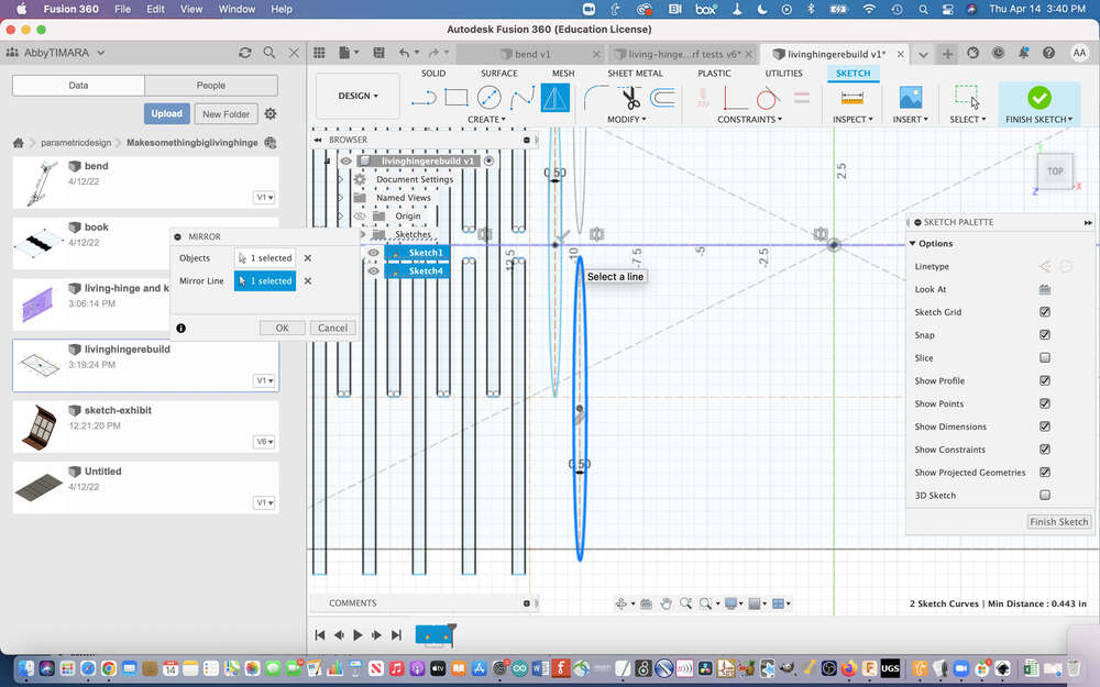
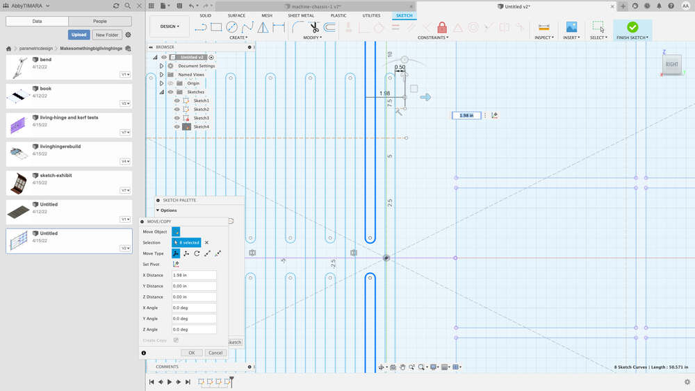
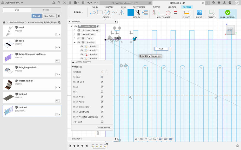
 I decided to skip the ovals in favor of a simpler design. As I mentioned previously, I had visited LCCC to check out a sampe living hinge my instructor had made in order to get a sense for what dimensions to use when creating my own hinge. I created rectangles with rounded ends and then made a rectangular pattern:
 I then stretched this across the relevant portion of the material…
 …and cleaned up the tops of the rectangles in the design.
Window in Fusion
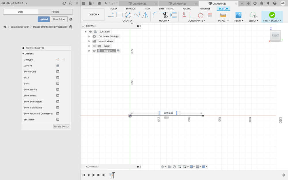
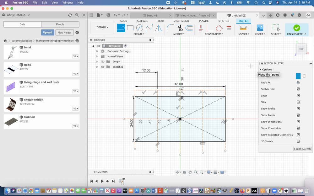
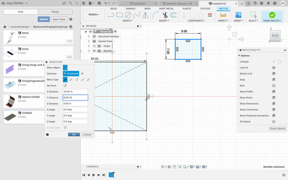
Most of the length of the plywood was devoted to the living hinge, but a portion was designed to hold the lithophanes in small window panes. To design this part, I began by creating a 9 x 7 rectangle that would serve as one pane of the window:
 …and then made a copy:
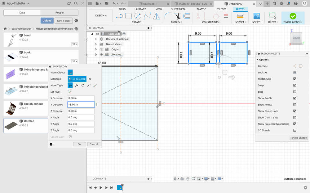 I made additional copies of the window pane and arranged them together
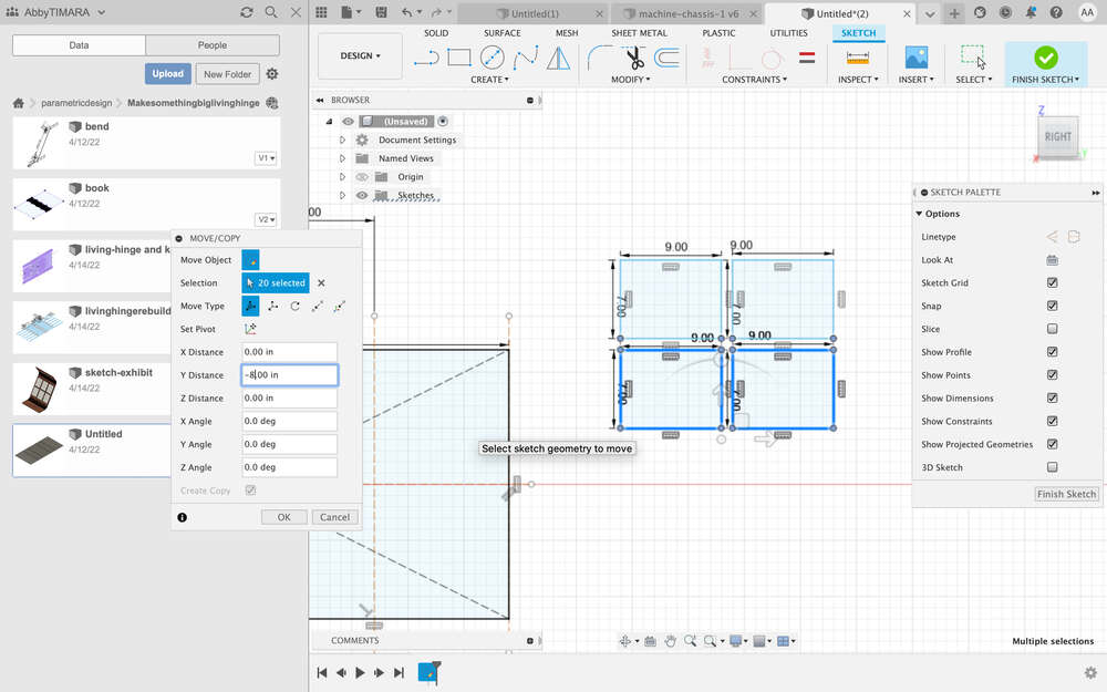 I placed the panes in the larger rectangle to create the window
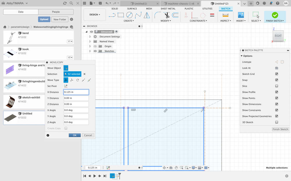 Tweaked the distance of the panes from the edge:
 Then I defined the distance from the edge of the material to the first pane:
Partworks with Living Hinge Design
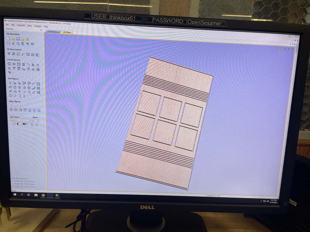
Here you can see the a view of the final design after I imported it into Partworks:
I stepped through the increasingly familiar process of defining materials, tools, and toolpaths in Partworks, and reviewing renderings of the cuts:
Assigning inside/left cut for windows:
 View of rendering of just windows having been cut:
 Close up of tabs for windows:
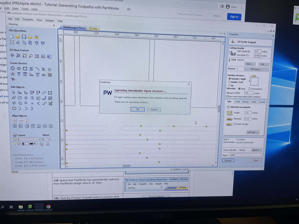
 Error message about ignoring unstuitable open vectors:
 Rendering of living hinge:
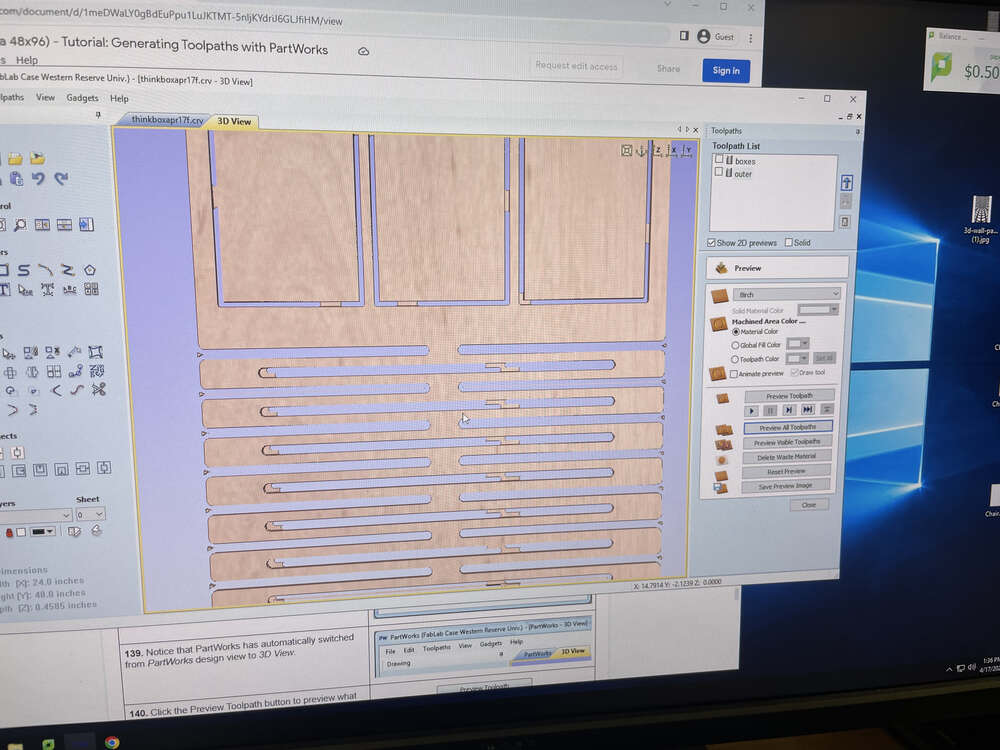 Another view of living hinge, showing more of the workspace:
Fabrication Process…again!
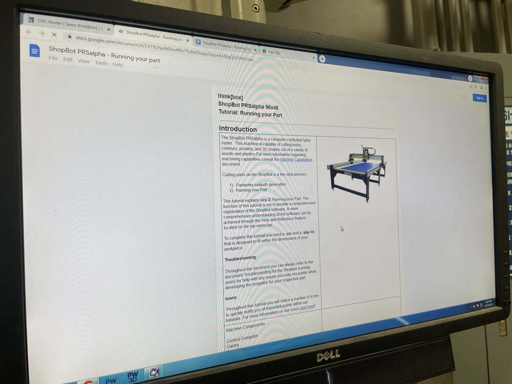
As before, I visited the training documents to work through the CNC file preparation and machining process. Here is the training documentation landing page at Think[box].
 Training document regarding ShopBot CNC mill at Think[box].
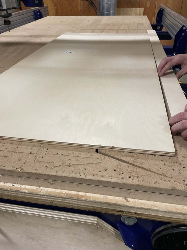
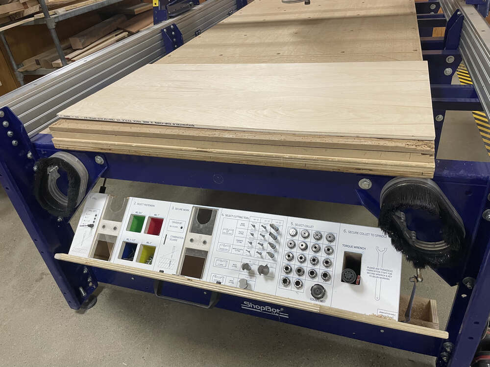
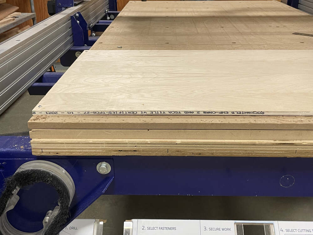
 Plywood laid out on shopbot bed. Note organization of endmills/tools/collets, etc!
 Tools for squaring material to bed:
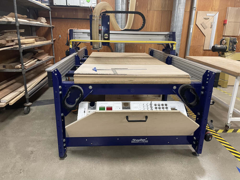 Computer controlling the shopbot:
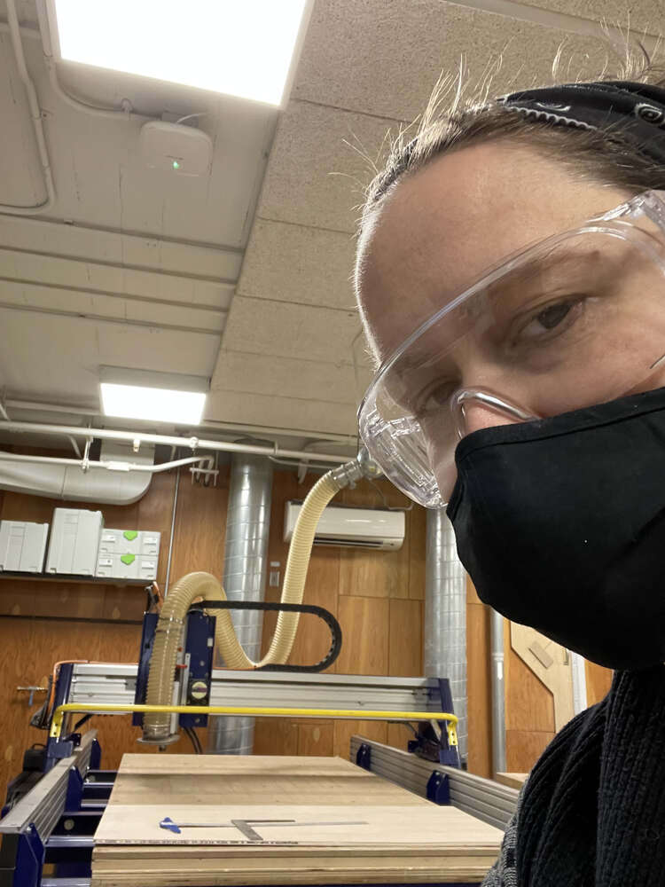
 Me in front of the shopbot. Previously, the student workers helped quite a bit, but this time I was able to complete more of the process myself while still being supervised.
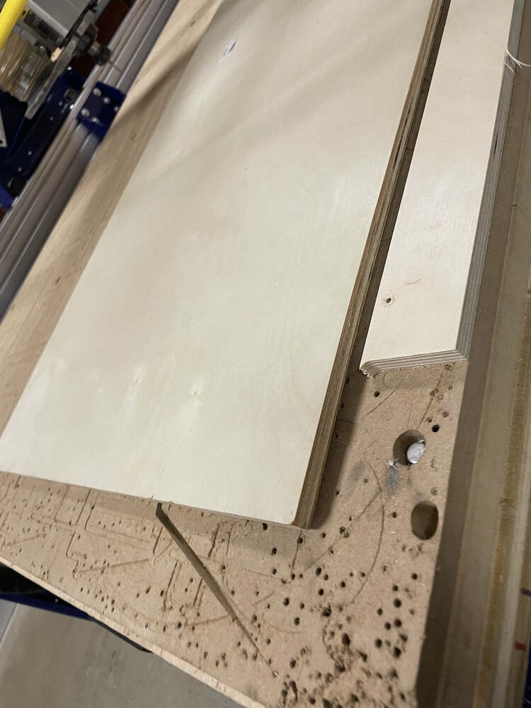
 Material affixed to the bed:
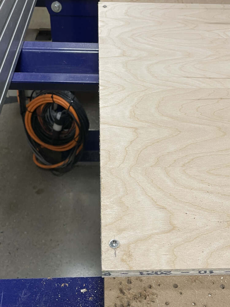
 Close up of screws affixing material to bed:
 Close up of screws affixing material to bed:
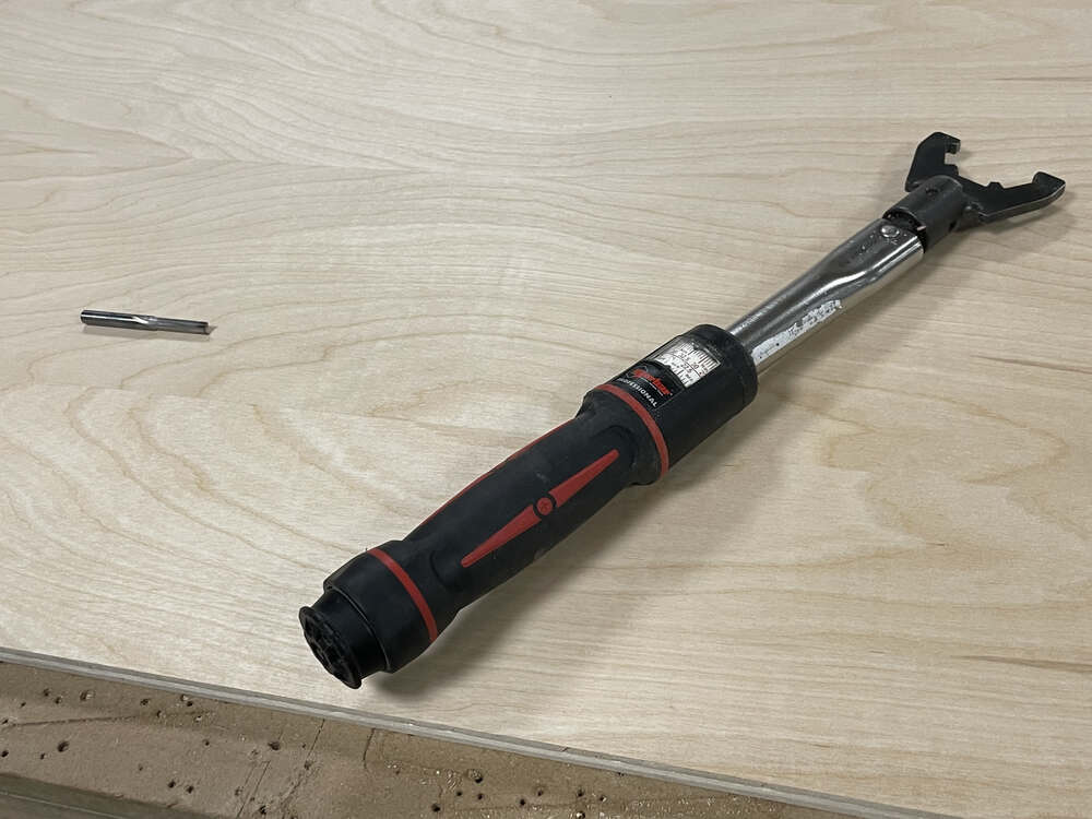
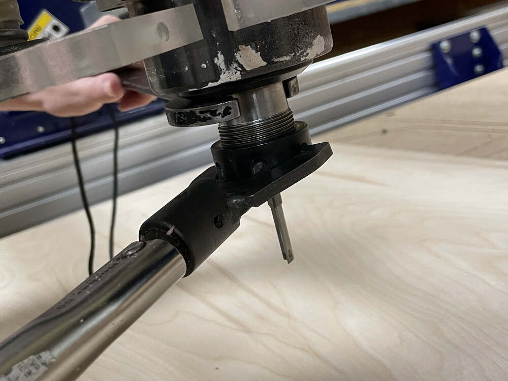
 Collection of different cutting tools. I used a 1/4 inch tool with 2 flutes and a cutting depth of one inch.
 The cutting tool next to one of the two wrenches required to tighten the cutting tool in place.
 All of the Shopbot tools in their very organized home:
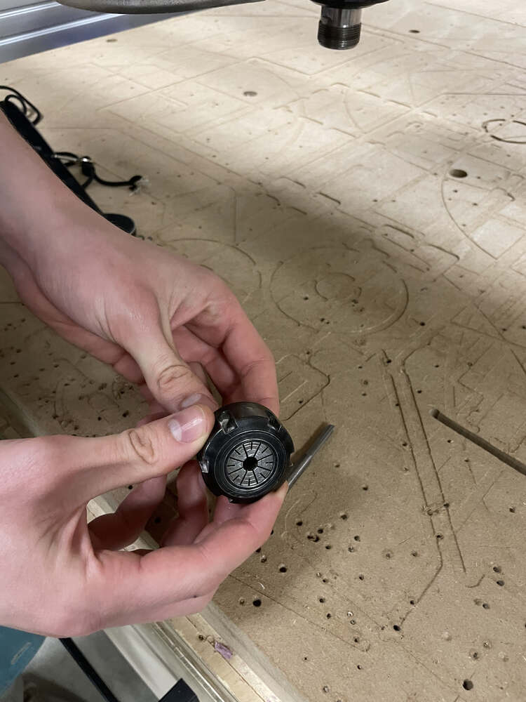
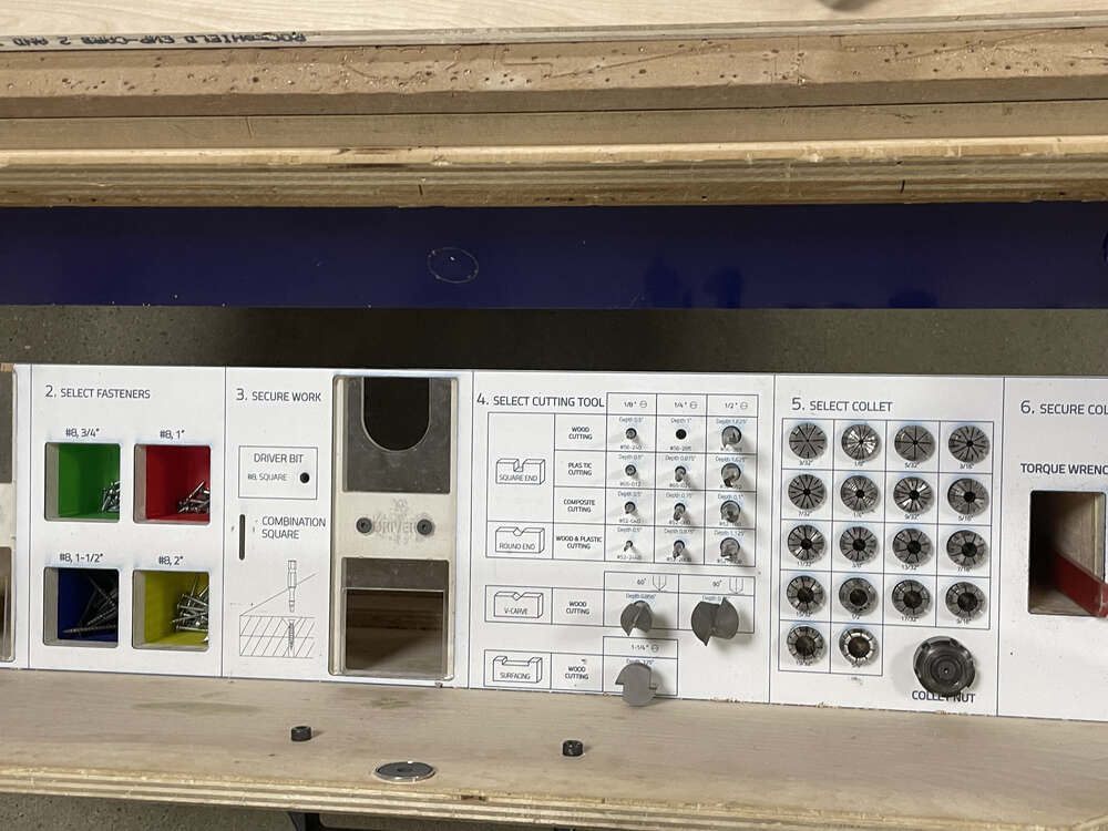 Close up of the collets and collet-nut:
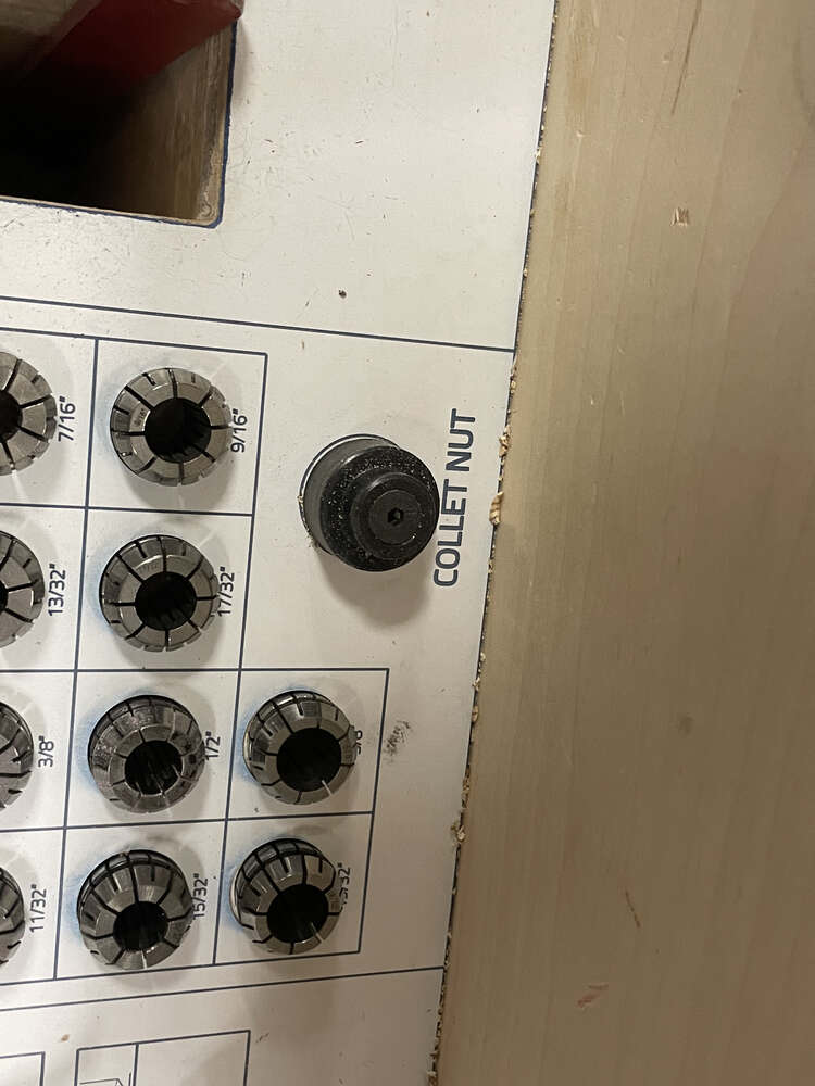 The tool and the collet I used:
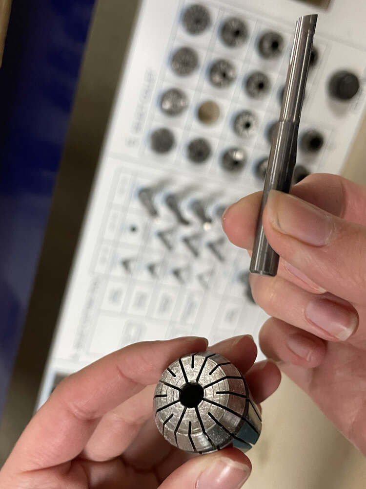 Putting the collet into place:
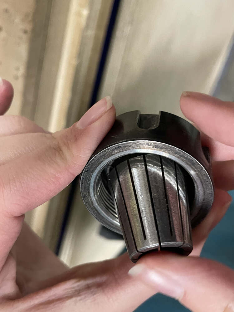 The collet is ready to place the cutting tool inside:
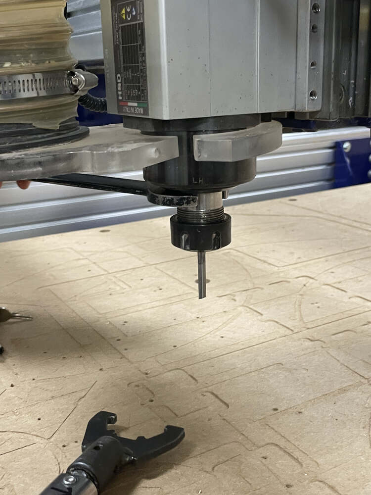
 The cutting tool and collet affixed to the spindle:
 To tighten, place one wrench on top:
 And then place the special wrench on the bottom:
 Pull both wrenches apart from each other to tighten:
 For safety, the machine will not work without its key. The key is stored at the front desk:
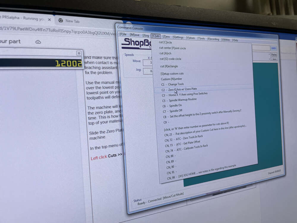
 The ShopBot software interface:
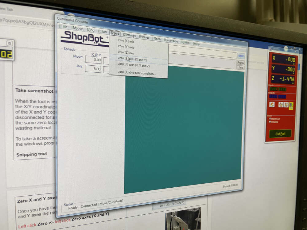
 Begin by zeroing the X and the Y axes:
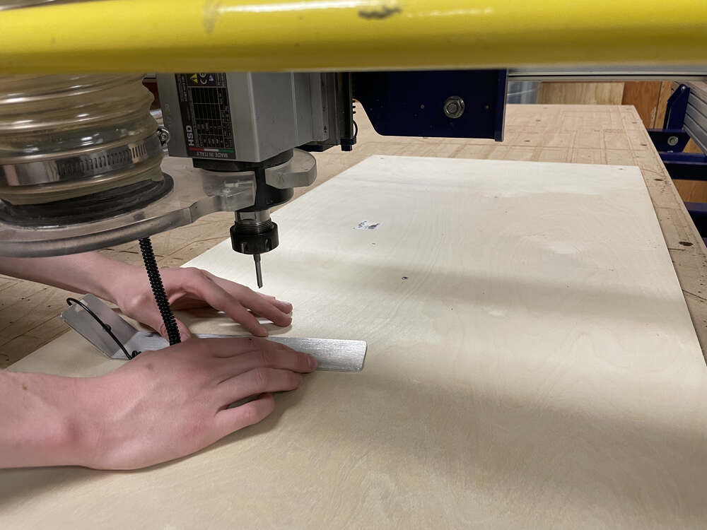
 To zero the Z axis, there is a special conductive plate that is used.
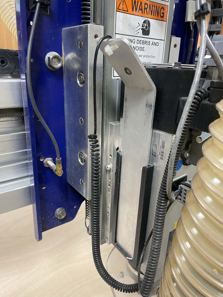 You place the plate directly under the cutting tool:
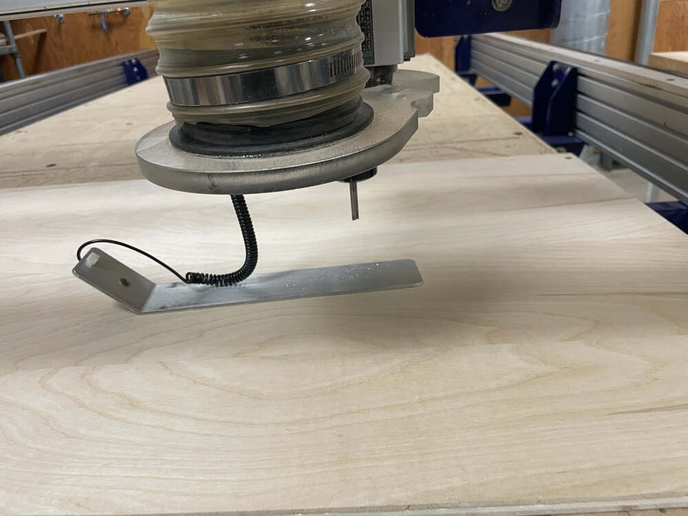 And then zero the z axis using the zeroing plate:
 Hit enter when your set up is ready and you have the plate in place, but not before or you will damage the machine / cutting tool!:
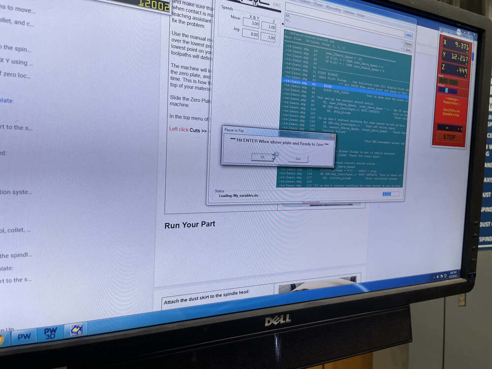 The machine zeroing itself with the zeroing plate:
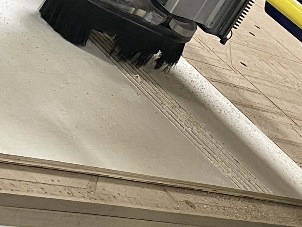
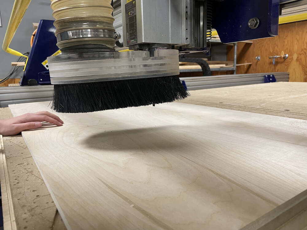
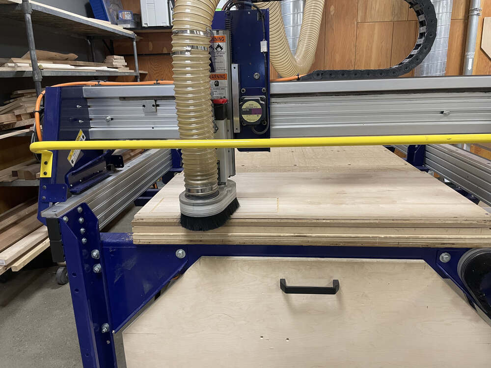
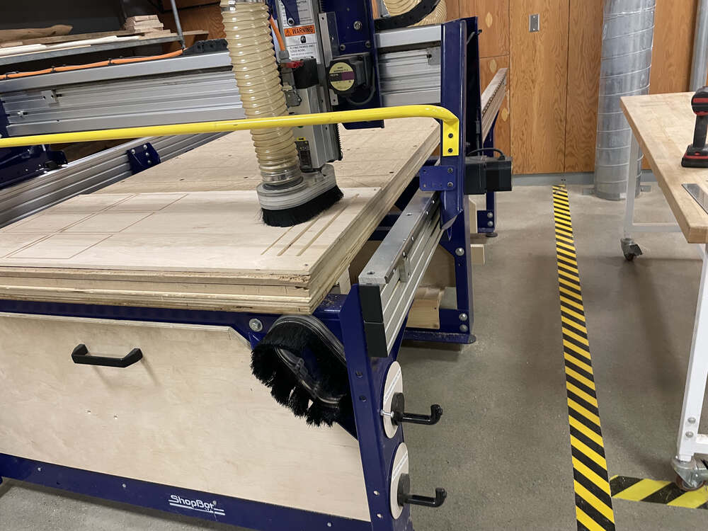
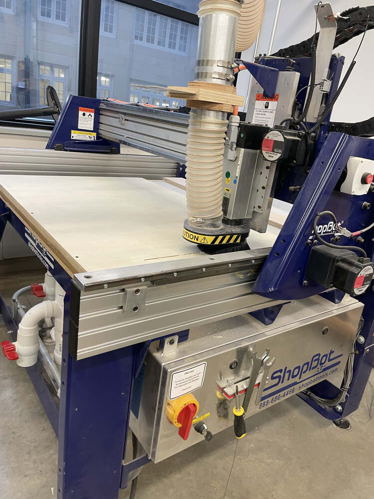
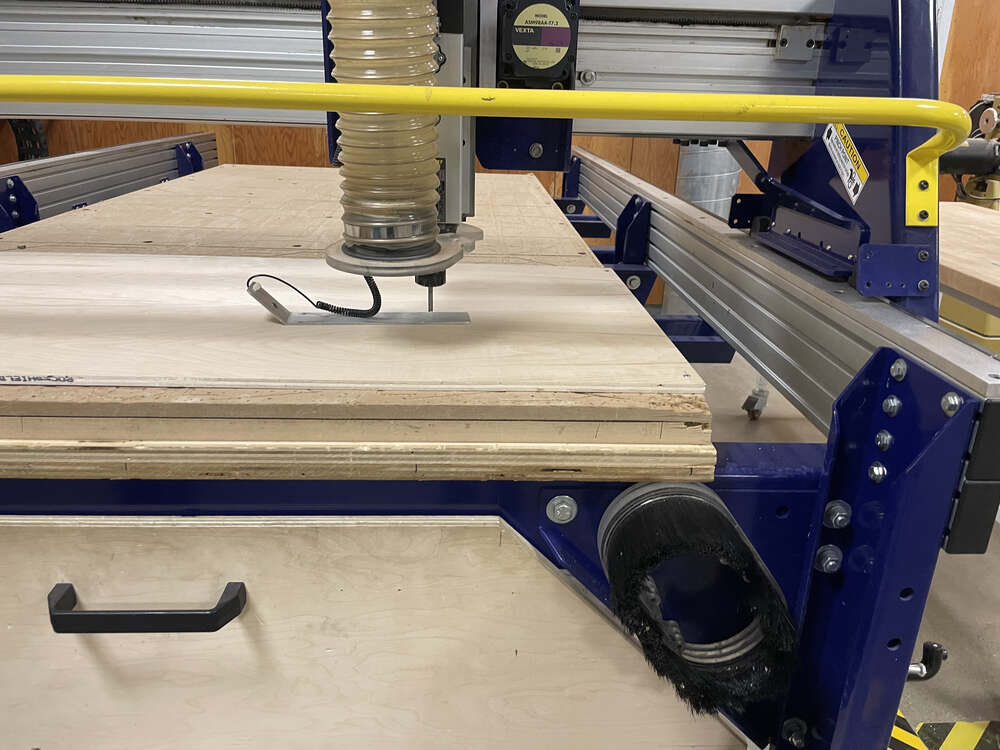 This attachment helps to keep the cutting surface clear, removing some of the sawdust while the machine works:
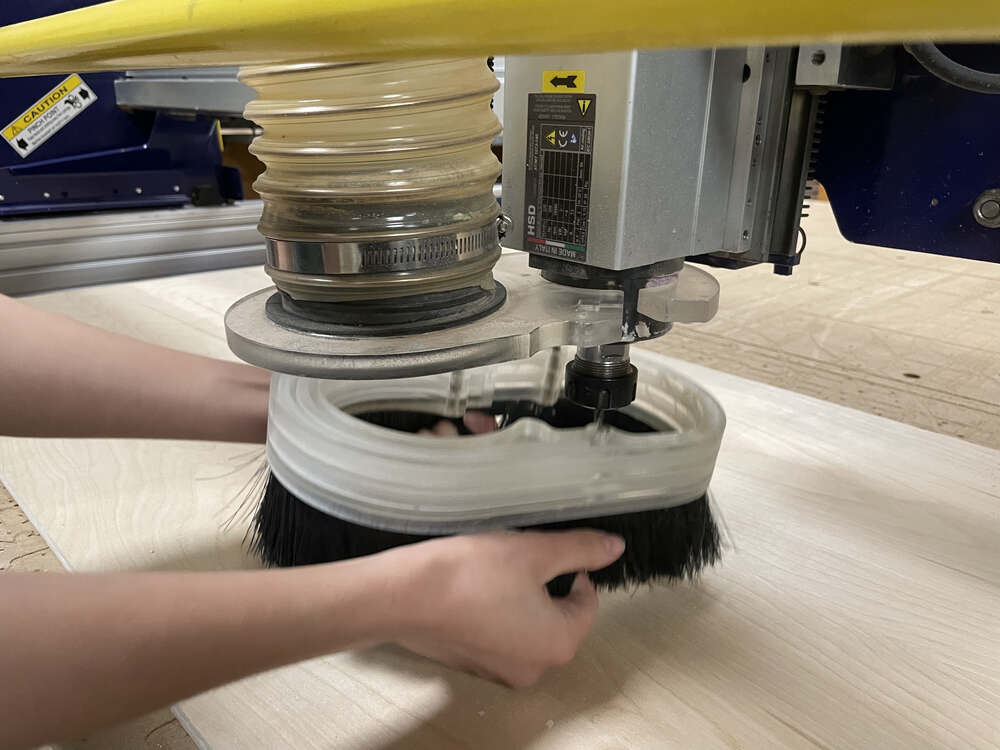
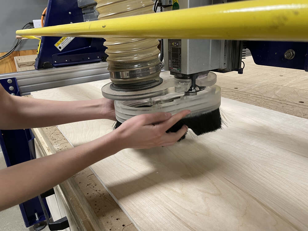 It has magnets that keep it in place:
 Close up of the magnets:
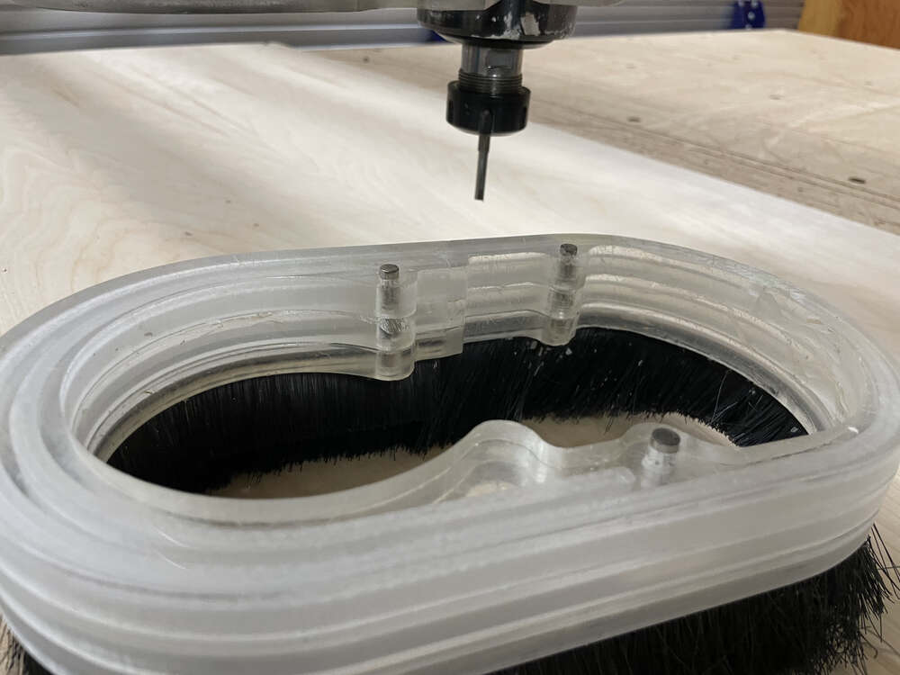 It snaps right on:
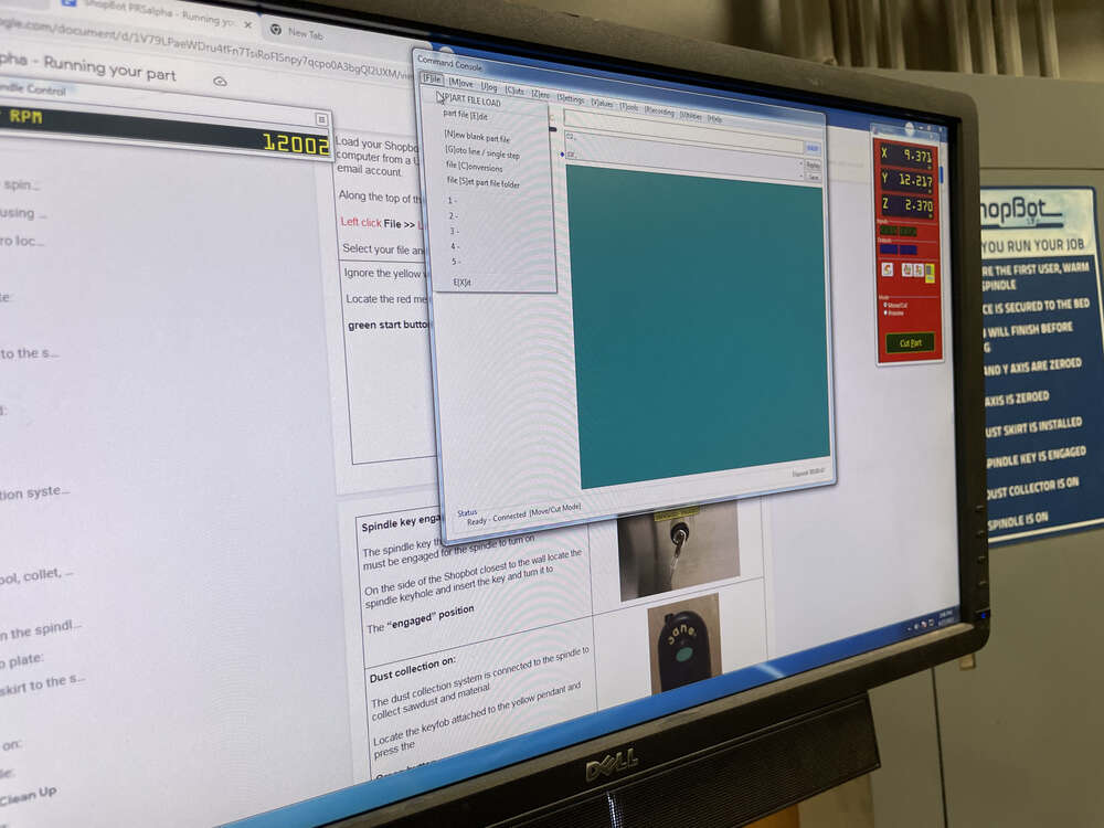
 Now it is time to load the file:
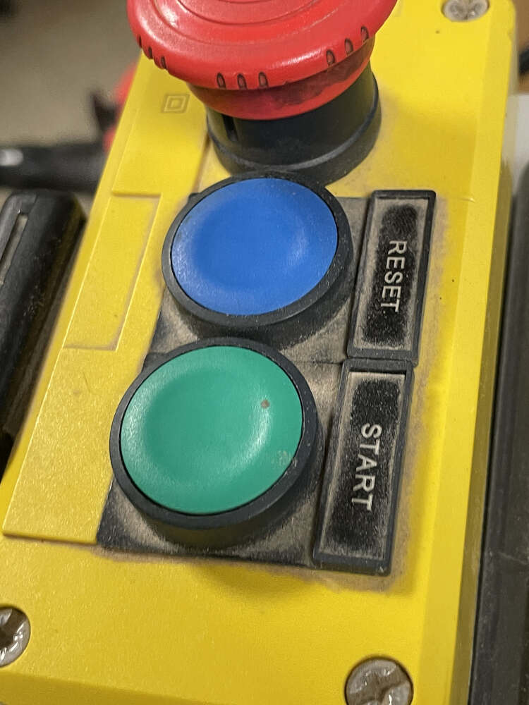
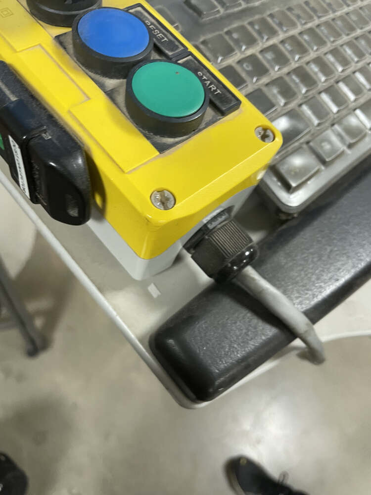
Main controls. The big green button means ‘go’:
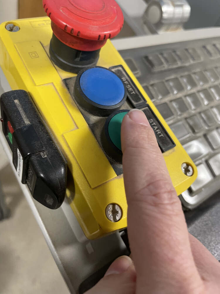
 Pressing the big green button:
 Confirm that you have inserted the correct bit:
 Hit go again
 Oh no! One of the student helpers who was assisting me had tweaked the placement of the design on the material in the ShopBot interface because there was an error in the original file…but when that student had to move to a different task and another student came to help, they forgot to share this info. As a result, when the machine started to cut the deesign, it started too high up on the plywood and we had to abort the cut.
So, we tried again, and this time it worked! Below you can see several action shot:
Cutting a version of the design that we rotated 180 degrees:
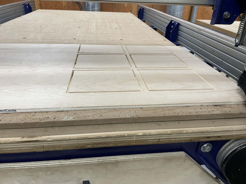
 Cutting the windows in the plywood:
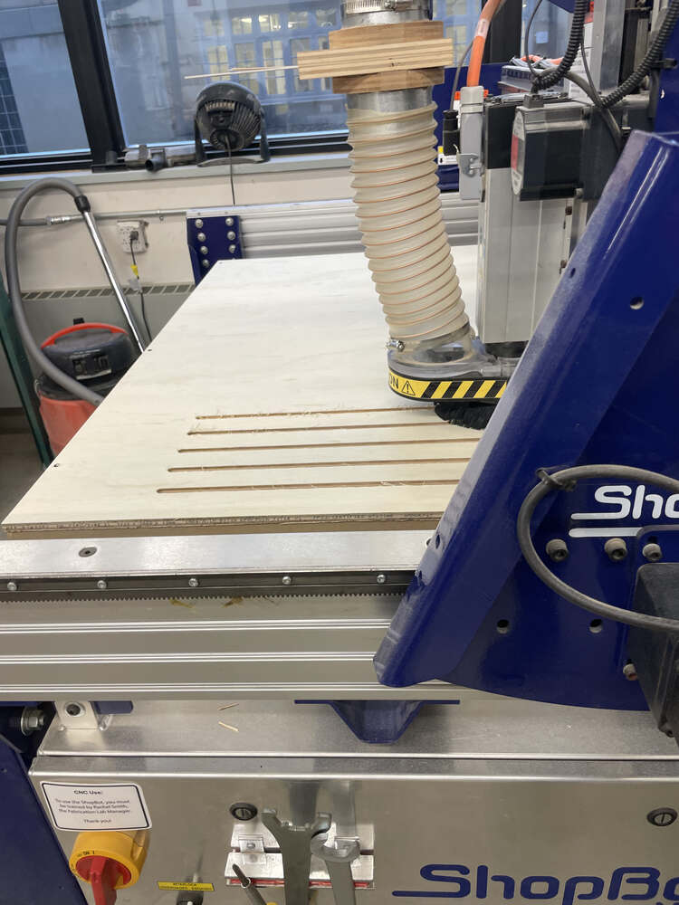
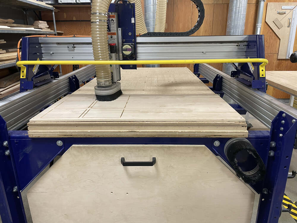 Cutting the living hinge. It started with a single row of straight lines:
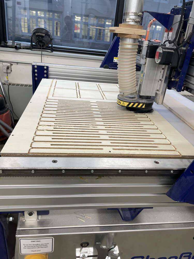
 More od the living hinge, completing a second pass:
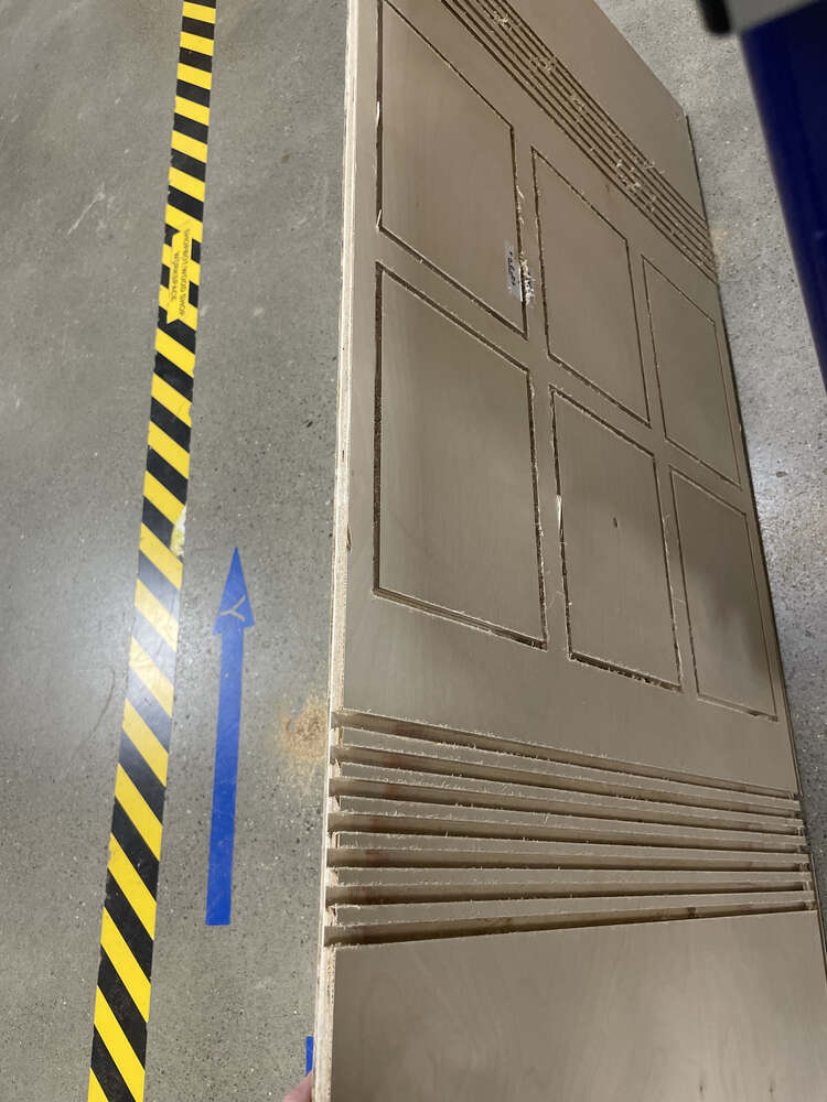
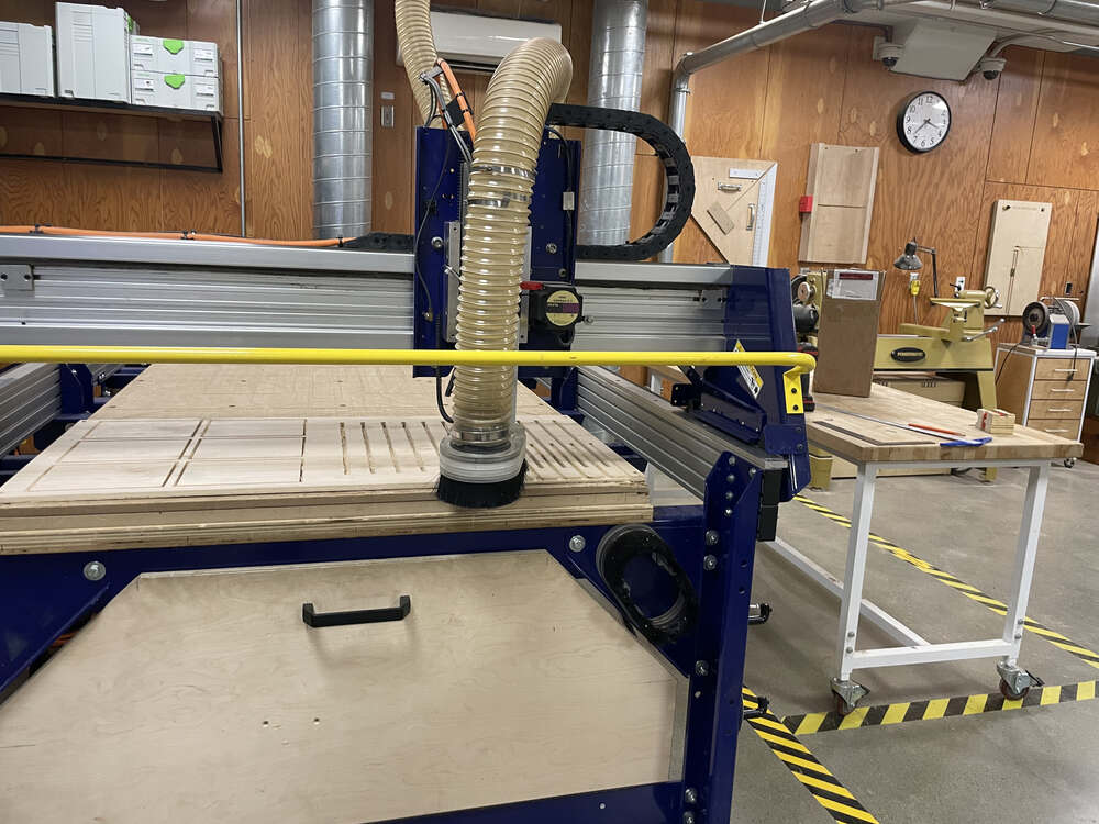 The finished living hinge before the material is removed from the Shopbot:
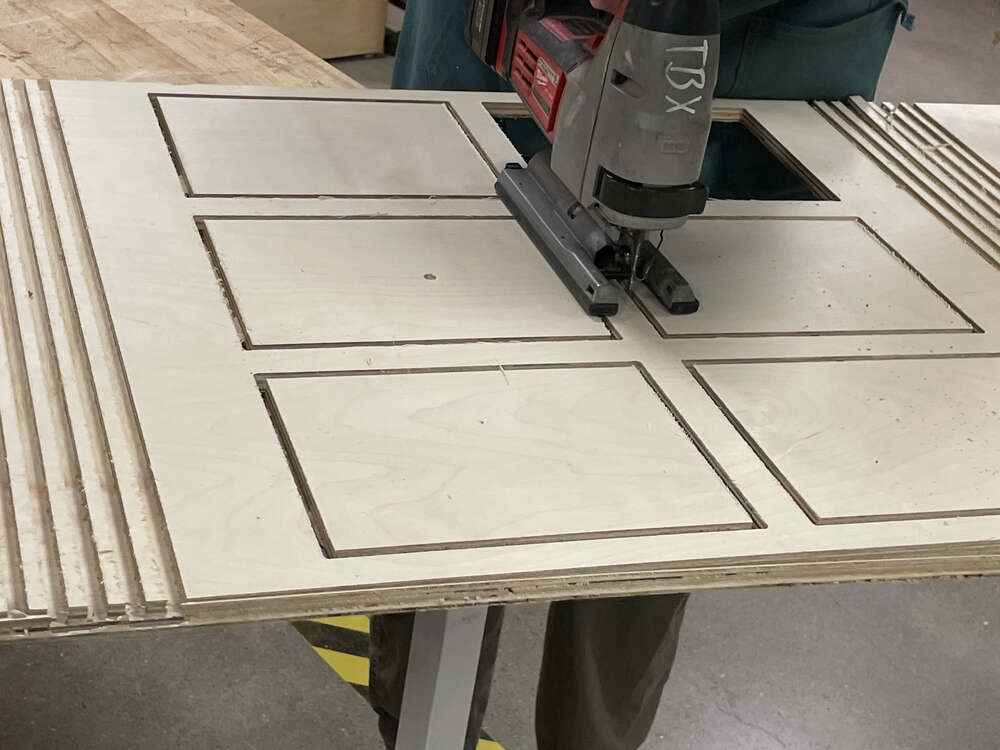
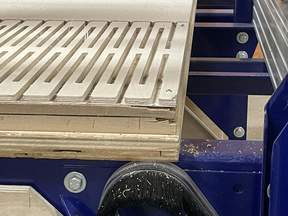 After the ShopBot finished its work, I had a lot of work to do. For starters, I needed to cut the the tabs out of the window pane segments in order to release the windows from the larger structure.
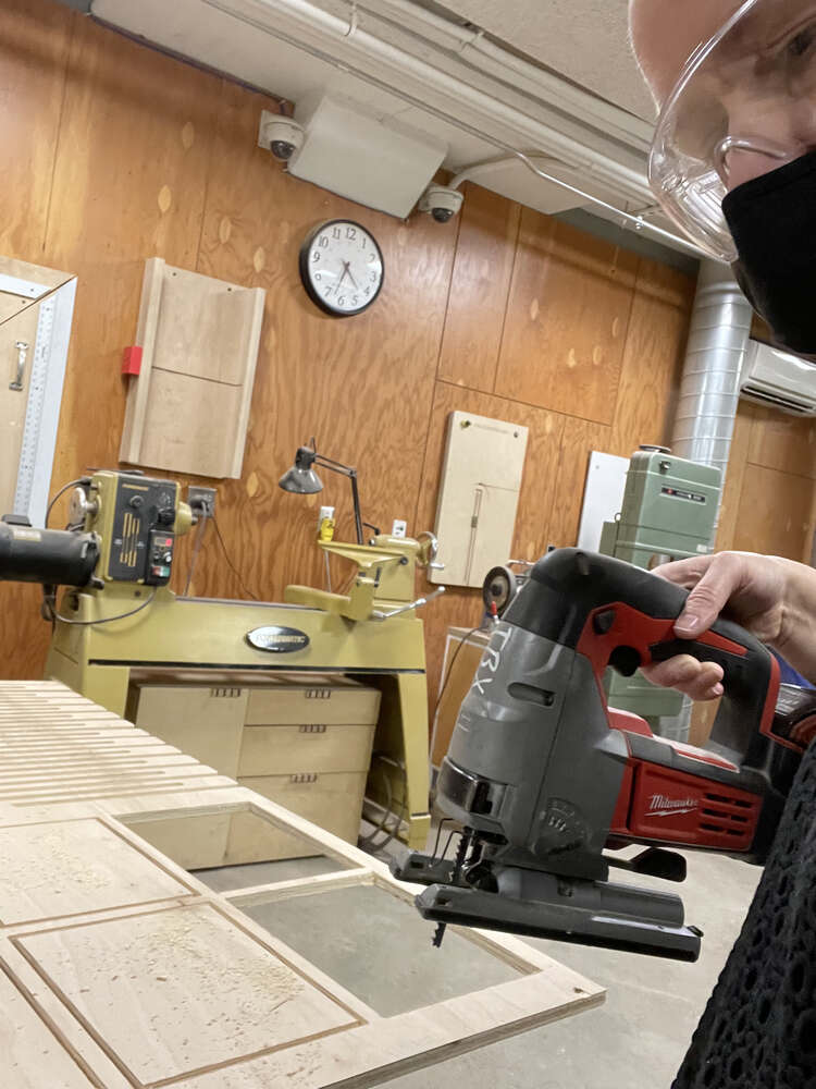 Another view of me with the jigsaw:
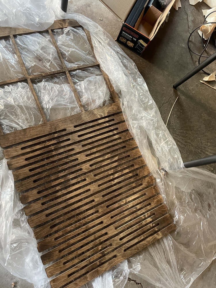
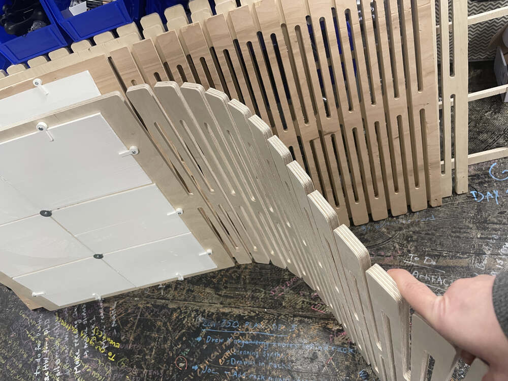
Look, it curves!!
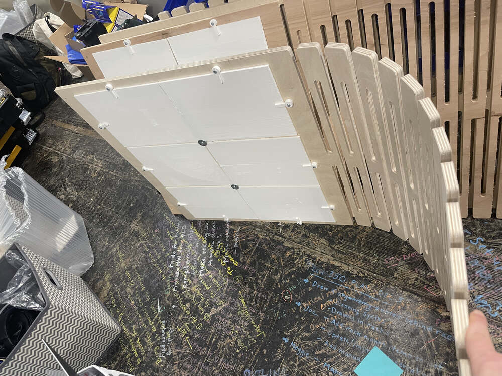 And it curves some more!
 Cutting on a mini Shopbot, closer to home
 First cut!
 More living hinge cuts, continued
 Almost complete!
 Staining process
 Staining process