5. Electronics production
Our Homework this week:
Our assignment this week is to:
Group assignment:
- Characterize the design rules for your in-house PCB production process: document feeds, speeds, plunge rate, depth of cut (traces and outline) and tooling.

- Document your work (in a group or individually)
- Document your work to the group work page and reflect on your individual page what you learned.
Individual assignment:
- Make an in-circuit programmer that includes a microcontroller by milling and stuffing the PCB, test it to verify that it works.
Learning outcomes
- Described the process of milling, stuffing, de-bugging and programming
- Demonstrate correct workflows and identify areas for improvement if required
Have you answered these questions?
- Linked to the group assignment page
- Documented how you made (mill, stuff, solder) the board
- Documented that your board is functional
- Explained any problems and how you fixed them
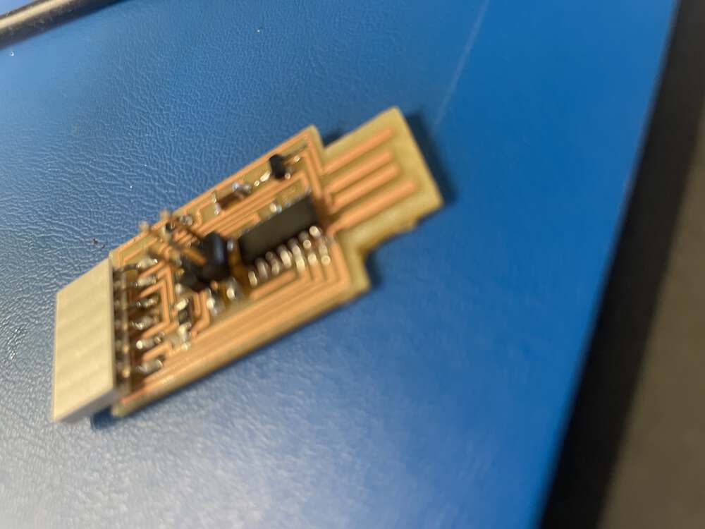
- Included a ‘hero shot’ of your board
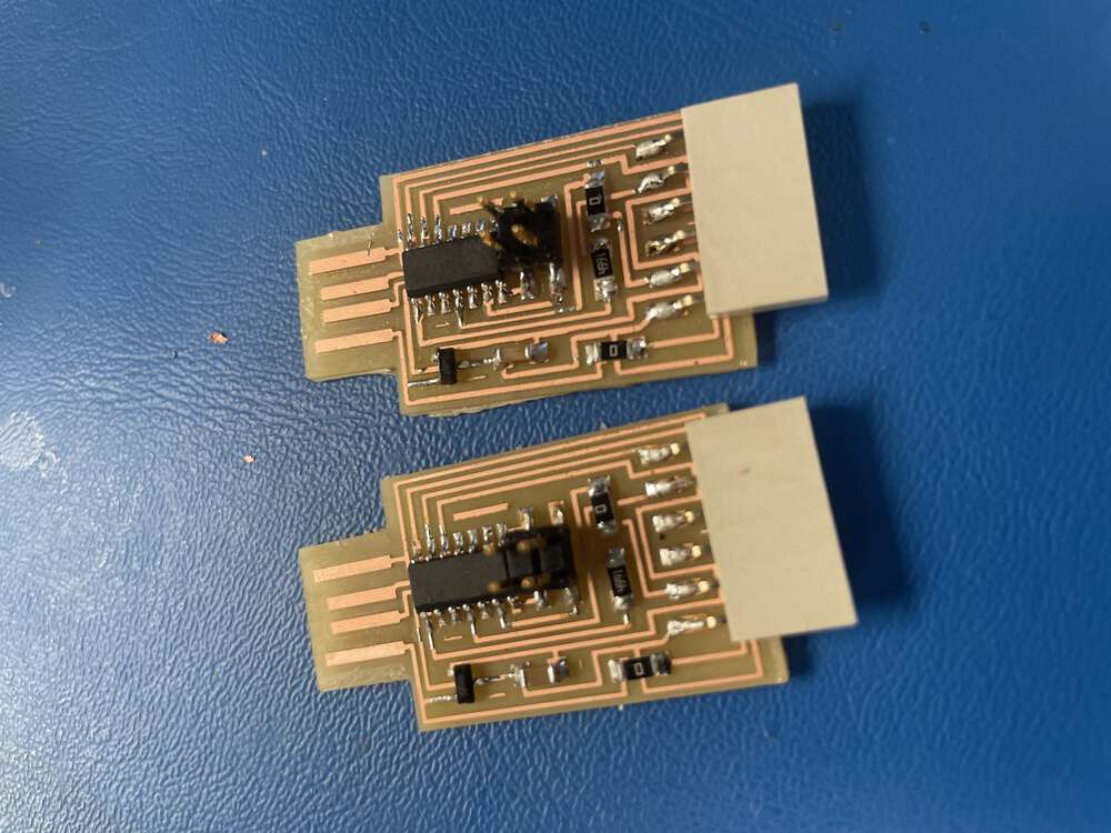
This week, I made two in-circuit programmers in case one did not work:
Some Potentially Useful Resources
As usual, I checked the sites of some Fab Academy alums and classmates to try to better understand the group and individual assignment for this week. In particular, I reviewed the sites of Adrian Torres, Nadieh Brehmer, and my fellow LCCC Fab Academy student Jim Hart. I also wanted to dig a bit deeper into some terminology, and reviewed the resources linked below:
- Calculating your cut settings by inventibles - I paraphrased this article for most of the definitions below.
- Feeds and Speeds - I had never heard of slew rate before!
- Stepover - addresses stepover, which some other articles missed. This article also helped.
- Stepcraft CNC - another good general overview of terms, including plunge rate.
I also sought out resources about the specific equipment I am using and the workflow for some of the different tasks required to complete this assignment. These resources include:
- A great video about building and using the SainSmart 3018 Prover
- Part 2 of the series
- I also found these instructions from someone who also is working with a SainSmart Genmitsu.
- Neil’s video from 2021 shows the workflow in the older version of mods during the class lecture at 1:07. Here is another link to the video on the Fab Academy site. Note that as of 2022, modsproject.org is the newer community-maintained version of mods.
- Since I wasn’t doing much traveling last year, I decided to spend my annual professional development funds on a desktop mill. I had a written a grant to hire a 2021 alum to continue working over the summer, and thankfully she had a ton of engineering background. She made this guide for us.
Group Project
Terms and Definitions
Below I review terminology related to several important milling measurements primarily as defined in the Inventables article. I also grabbed a few bonus terms from the other sites linked under the resources section above.
- The “feed rate” is the rate at which your machine advances along the X and Y axes. The feed rate is measured in distance per time, for example, inches per minute. The precise units may depend on your specific set up. While there is technically a relationship between the feed rate and rotation speed of your spindle, depending on your set up, the feed rate may be controlled independently of the rotation speed of your spindle. The feed rate does not impact the Z-axis at all.
- The “speed” or “spindle speed” of your machine is measured in rotations per minute; this measures how quickly your spindle is spinning.
- The “plunge rate” is the rate at which the endmill enters the material. Since endmills are designed to cut from side to side and not up and down like drill bits, you have to be cautious about this speed. One article above suggested a plunge rate of 10 mm per second or less.
- The “depth of cut” or sometimes “depth of pass,” measured in inches or millimeters, refers to how much material your machine is carving away in a single pass. When you want to cut a deep line in a material, you generally can’t do this in a single pass without risking breaking your tool. Instead, you will tell your machine to complete the same tool path several times. With each iteration of the tool path, your machine cuts a bit deeper into the material since some of the original material was already cut away. The depth of cut or depth of pass is the amount of material cut away with each tool path. One rule of thumb I read was that you should use a cutting depth that is not more than half of the cutting diameter of your tool. So for a tool with a 1/4 inch cutting diameter, your cut depth should not exceed 1/8th inch. In general, it is best to be more conservative; these represent the maximum allowable cut depths, not the best cut depths!
- The “chip load” describes how much material is removed by a single “flute” or “tooth” on your bit. This is measured in feed per tooth.
- Larger chip loads: Because larger chips remove heat from near the cutting area more quickly, it is sometimes desirable to have a larger chip load when working with materials that are susceptible to melting, like plastic. However, you can easily break a bit if your chip load is too large. TO decrease your chip load, decrease your feed rate, increase your spindle speed, consider decreasing your depth of cut/pass, and swap out your tool for one with more flutes, where possible.
- Smaller chip loads: While smaller chip loads are generally easier on your machine, chip loads can be too small, in some circumstances. Chips that are too small may become airborne, which is a health hazard. They can also cause “rubbing” or “burnishing” which is when your tool is just rubbing up against your material and not removing it. This will cause your bit to get hot and may dull your bit prematurely over time. To increase your chip load, you increase your feed rate, decrease your spindle speed, and/or use a tool with fewer flutes.
- The “slew rate” refers to the rate at which the machine moves between cuts, when it is moving to the next tool path. This is generally set to a faster speed to save time, since the machine is not cutting through any material.
- Step over addresses the tool path offset. It is often defined as a percentage of the tool’s diameter. A really small stepover will give you a very smooth finish but may take a very long time. A large stepover may machine quickly but will give a very rough end result.
Tooling: We will explore tooling in more detail in later course segments. I am using the recommended Carbide Depot 1/64th inch (0.4 mm) endmill for the traces and the 1/32nd (0.8 mm) endmill for cutting around the perimeter.
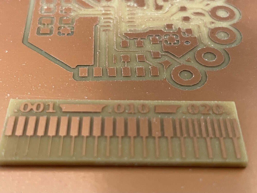
Here is a link to Neil’s line test.
Here is a link to the file to cut around the perimeter of the board.
Here is the line test I completed on my mill:
Documentation of in-house PCB production process:
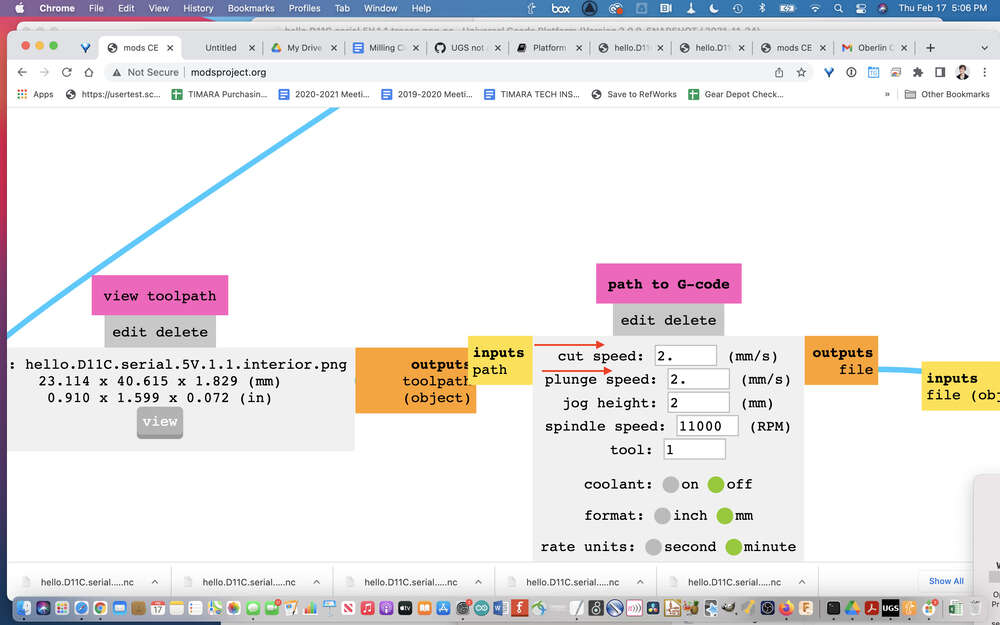
Below I outline the values I assigned for the line test using mods:
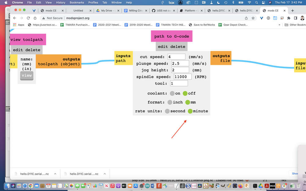
- Feeds:I am assuming that the ‘cut speed’ in mods refers to the feed rate. If this is the case, we set this parameter to 4 mm/second.
- Speeds: I have always left the default spindle speed of 11000 RPM, but it turns out my machine can only mill at 10,000 RPM. I haven’t had a problem, so I think it is just going as fast as possble.
- Plunge Rate: For the traces this was set to 2.5 mm/second which did not seem to be a problem. But, we had issues with the exterior file and changed the plunge rate to 2 mm/second. This is much less than the 10 mm/second rule of thumb listed above, so they must be dealing with different types of materials or other factors.
- Depth of Cut: For the exterior file, we changed this from 0.024 to 0.018 so that more passes would be required to cut through the material. The endmill broke when attempting the deeper cut. -Offset: I see two values listed for offset, one being the offset number and the other being the offset stepover. The latter is set to 0.5, which I assume is 50% of the tool diameter. The offset number is set to 4, but I’m not sure what the units are for this value.
- We are using a 0.4 mm endmill for the traces and a 0.8 endmill to route the exterior.
What I learned:
Reviewing this terminology and my documentation of the PCB milling process has helped me to better understand the different parameters available to manipulate in mods and some of the relationships between these parameters. In particular, it has helped me to imagine how I might troubleshoot these settings like my instructor did early on to help me get set up.
Milling
To mill the board, you will need:
- A mill
- A sacrificial layer of material to place on the bed of your mill
- A 1/64th end mill for traces
- A 1/32nd end mill for cutting the perimeter of your board
- The two wrenches that came with your mill
- An FR1 (NOT FR4) copper board*
- Double-sided sticky tape
- A PNG file for the board you plan to fabricate
- A gcode file (we generate these from png files in modsproject.org)
- Software to talk to your mill (Many use modsproject.org for this as well; I used Universal Gcode Sender)
*Safety note: it is important that you use an FR1 board which is safe for milling and not an FR4 board which contains fiberglass and should never be milled.
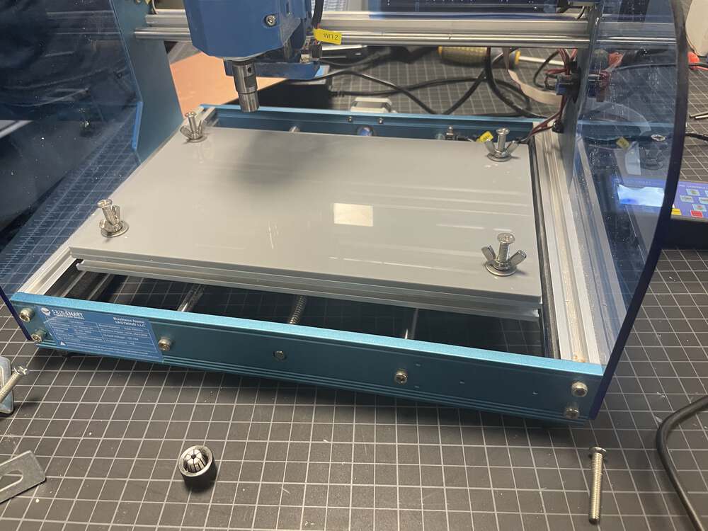
The mill: for this process, I used a SainSmart Genmitsu 3018-PROVer Desktop CNC Router. This desktop mill lives in the TIMARA studios and learning to use it is one of the reasons I wanted to take this class. As I mentioned above, a former student of mine helped set it up over the summer of 2021, but Fab Academy has been my first opportunity to really get comfortable using it myself.
The sacrificial layer: Over the summer when we first set up the mill, we were really scrounging around for a sacrificial layer. Chris L. helped me make a much nicer acrylic layer for the mill. This layer gets affixed to the mill and is replaced as needed. Make sure to use a material to which sticky tape will nicely adhere!
Here is an image of the file (thanks to Chris for all his help!):
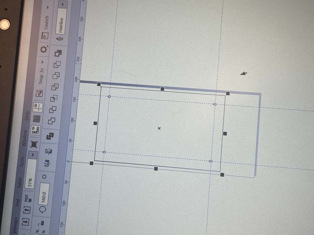
You can download this file in CorelDraw here
The end mills: I have included links to the recommended Carbide Depot endmills above. Originally, I did not have the 1/64th end mill and I very quickly broke my only 1/32nd end mill the first time I tried to zero the Z on my own. Thankfully, I was able to bring my mill to LCCC both to get help setting up the machine and getting comfortable with the milling process, and to borrow their end mills. You use the wrenches that came with your mill to tighten and loosen the end mills.
The FR1 board: the board I used is probably a bit on the large size for this project. It is important to make sure your board is flat (not warped) and level. You should place double-sided sticky tape evenly across the back of the board. Make sure no tape is overlapping and that the surface is smooth. Place the board firmly atop the sacrificial layer, pressing from the middle outward to make sure the board lays flat.
The PNG file: My instructors suggested I make this board. The file with the traces is here and the perimeter of the board is here.
Below, I go into a bit more depth about generating the GCode using modsproject.org, setting up the mill, and then using UGS (Universal GCode Sender).
Modsproject.org
In order to run your mill, you will need some gcode. To generate the gcode, we use modsproject.org. This site will take a png or svg and, based on the default parameters for the process you select (and any of your own modifications to these default parameters) it converts these images to paths represented by gcode commands that your mill can understand. These paths are exported as ‘.nc’ gcode files.
Step-by-step ModsProject Guide
Navigate to modsproject.org and right click to pull up the menu.

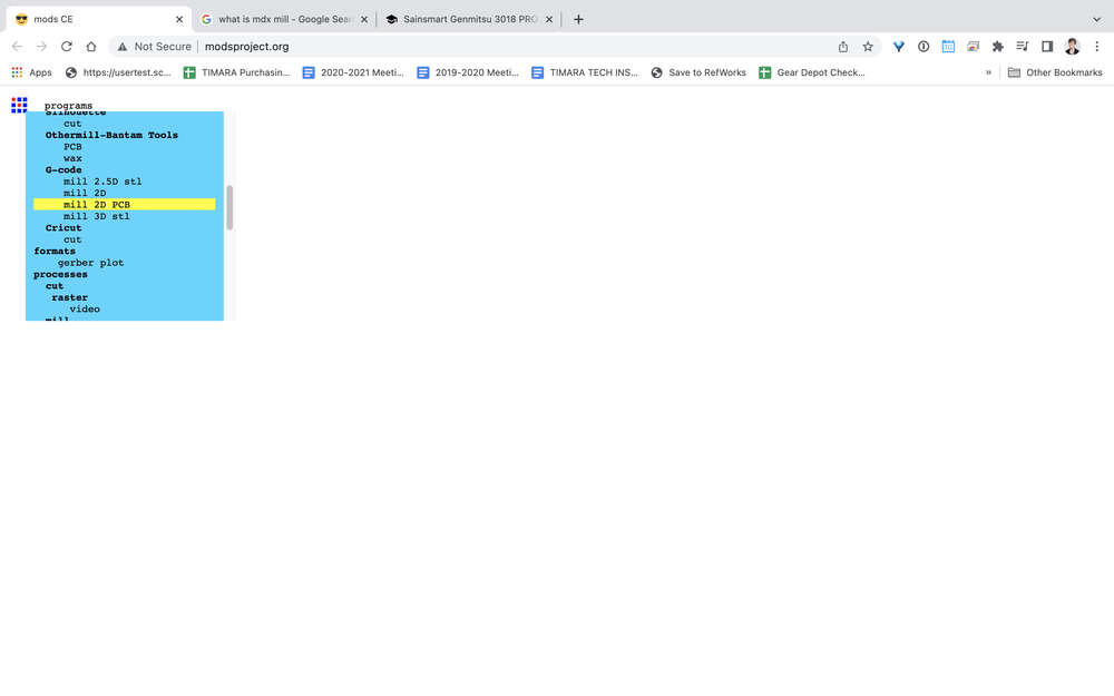
Click on programs:

Choose open program:

Choose GCode, mill 2D PCB:
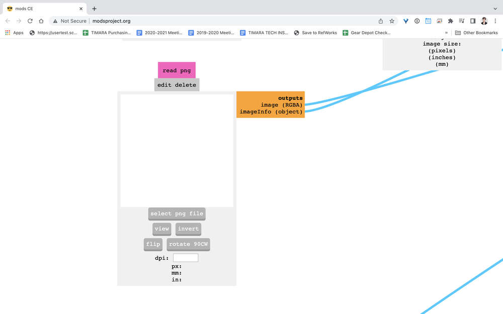
Use the ‘select png’ button in the module below to select your png for your traces:
Choose the file you want to upload into mods to create your traces:
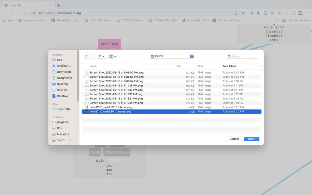
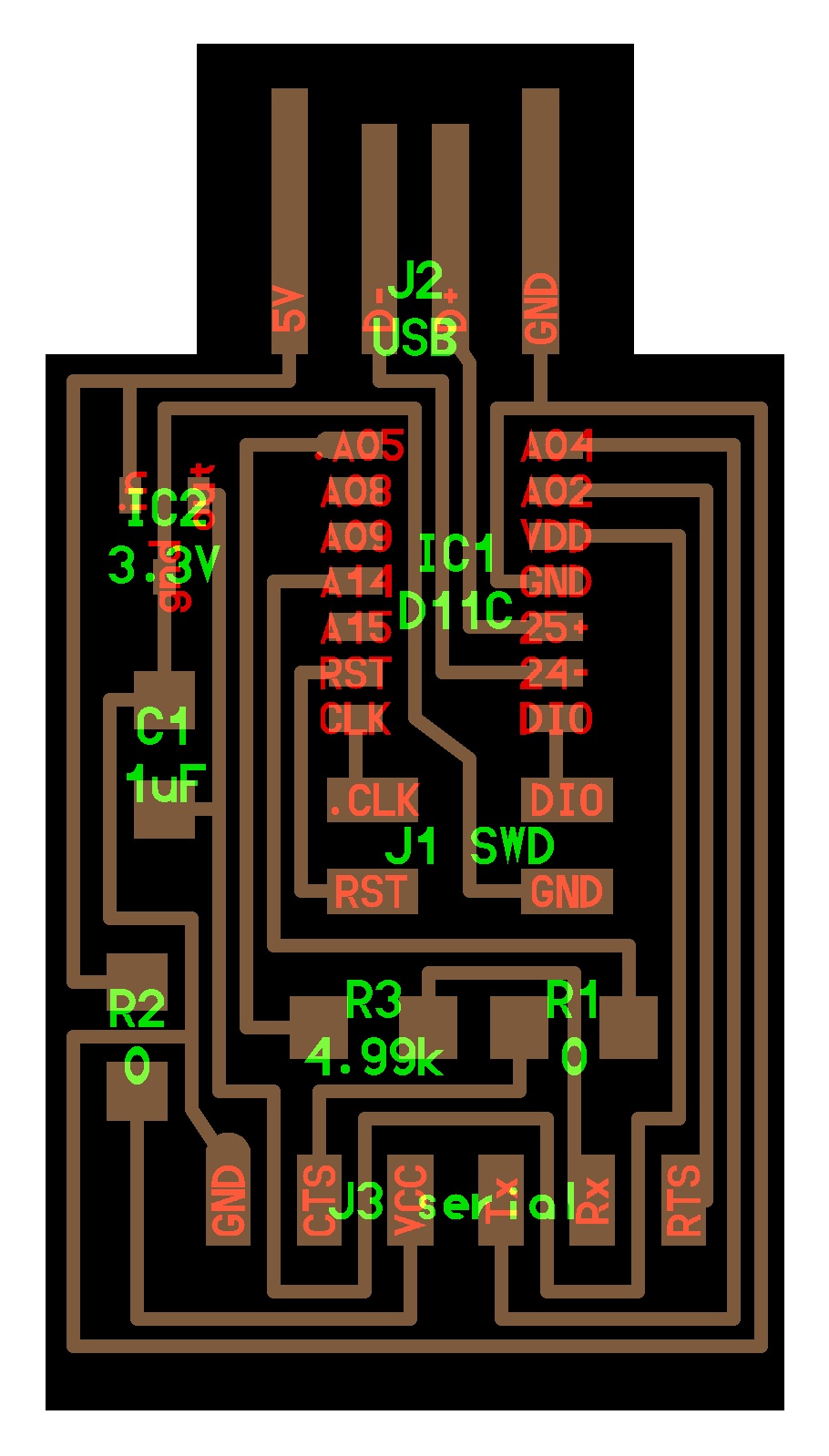
Here is the trace file I used, supplied by Fab Academy:

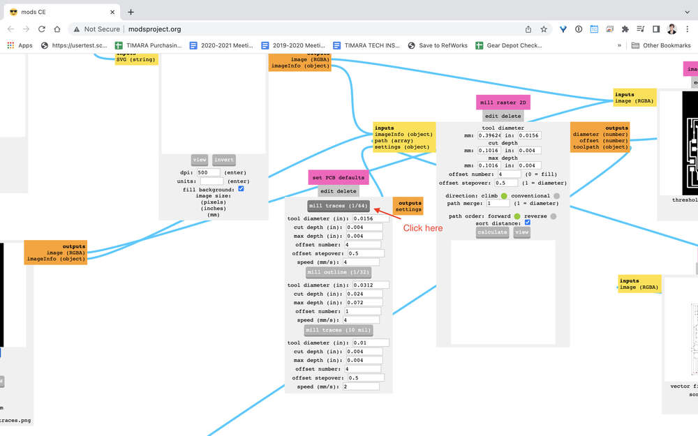
Next, you need to tell mods whether you are generating GCode for the traces of your board or generating GCode for the mill to cut the perimeter of the board. To do the traces, you want to mill traces with the 1/64 bit.
Click here to choose 1/64 for traces:
We were almost done with the traces, but had a quick moment of confusion. At first, it seemed like my mill was expecting GCode in mm per minute and modsproject.org was going to send it in mm per second. Mods has a place to specify this setting, but as it turned out, we discovered that mods was accounting for this conversion in the program already.
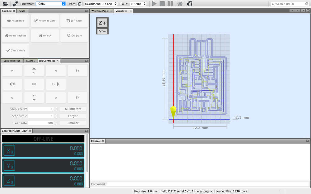
Once you are confident your settings are correct, click on calculate to get the traces:
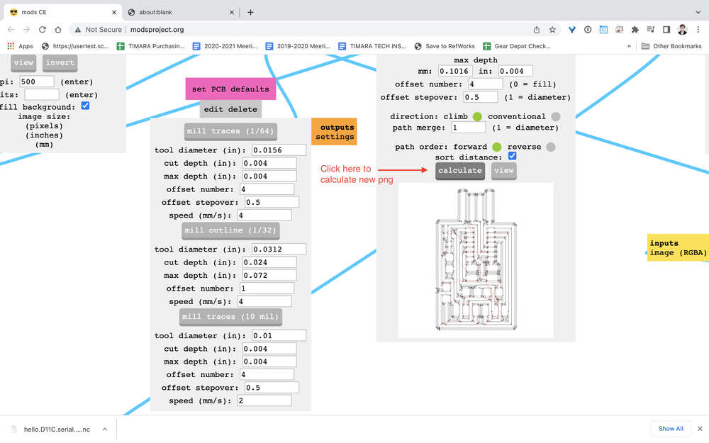
Take a moment to marvel at the beautiful image in your browser:
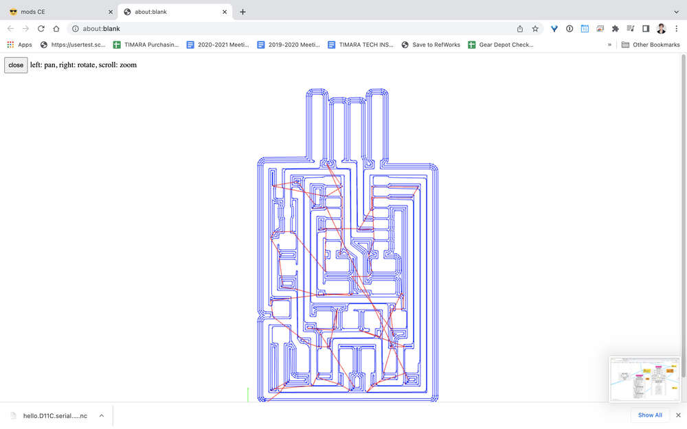
Note that what you really need is not the fancy browser image, but the .nc file that should be in your downloads folder. Make sure you know where it is, what it i called, and have stored it someplace safe.
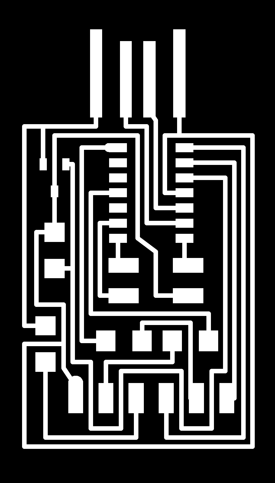
Next, you need to generate the GCode for the exterior path that will cut out the board itself. The process is basically the same as above. Here is the exterior file I used, supplied by Fab Academy:

You follow the same basic process in mods, choosing the 2D PCB milling program and selecting the desired PNG. You will choose the 1/32 cut option rather than the 1/64 trace milling option to calculate your Gcode file. Click here to choose 1/32 to cut the exterior:
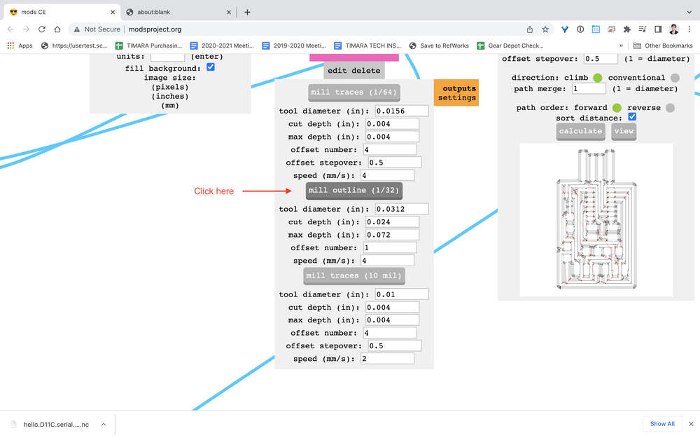
This time around, we had to tweak some of the default settings. We had to change the cut depth from 0.024 to 0.018. This was because we wanted to mill the board in four rather than three passes. (One of the end mills broke when trying to do the job in three passes.)
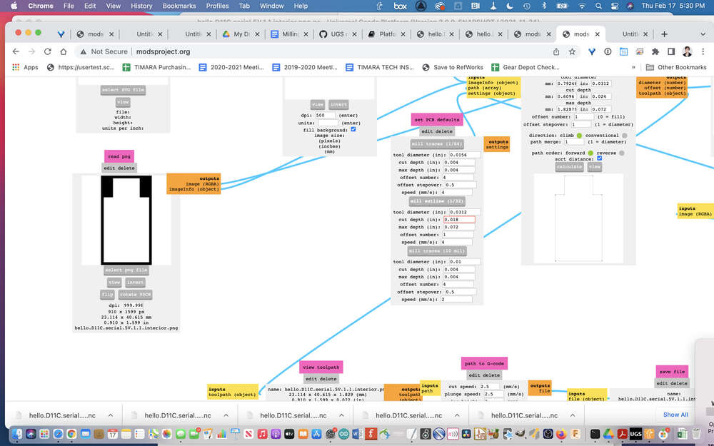
We also changed the cut speed and plunge speed both from 2.5 to 2. This generated Gcode set to 120 instead of 150, since the 2.5 or 150 setting broke a bit. While my instructor guided me through this process with a lot of hand-holding when I first worked on this week’s assignment, returning he group project to research the different parameters is helping to gain a better appreciation for ways I might need to manipulate settings in the future.
Note: after adjusting the settings, we calculated the GCode. While it seemed like the image of the file that is generated was going to try to cut the perimeter in a single cut, it actually generated just fine.
UGS and Setting Up the Mill
In this section, I go over the process of opening your GCode file, using UGS to zero your X, Y, and Z axes, and sending your project to mill the board. This assumes you have already prepared your FR1 board with double-sided tape and stuck it down to your sacrificial layer.

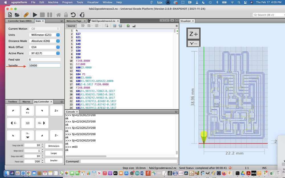
You can technically run the GCode you have generated directly from the SainSmart remote control using a microSD card. But I prefer to run the machine from my computer, using UGS. Here is the UGS workspace:
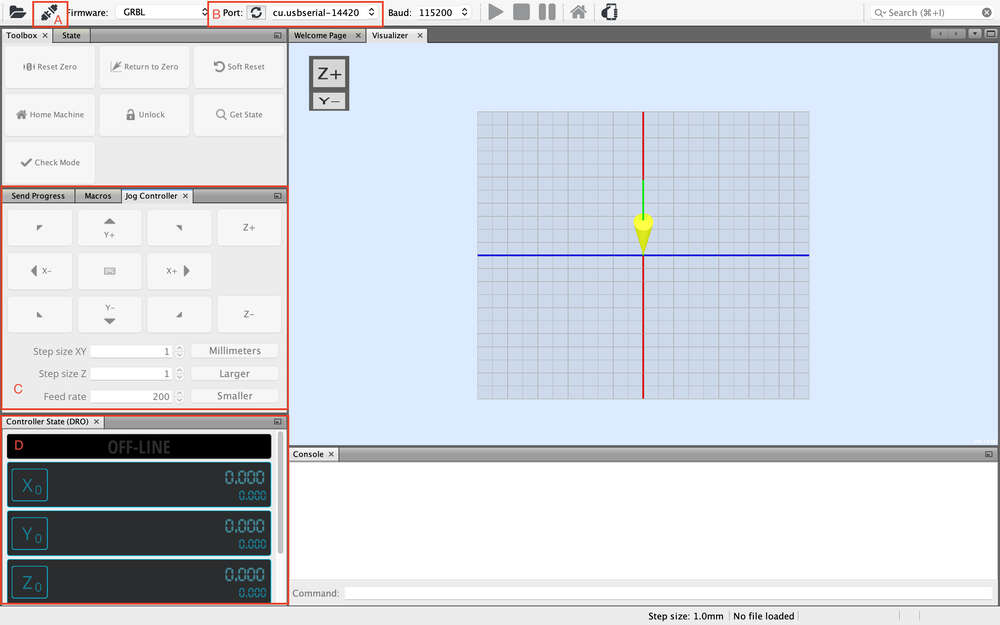
To get set up, begin by opening UGS and clicking the little circular arrow to reload the serial port connections. Select the appropriate USB serial port (See letter B, above). Next, click on the little button near the top left that looks like two plugs being connected (See letter A, above). When you click on this button, it should turn orange, and you should see a status message of either ALARM or Idle. If it says disconnected or you encounter another error, check your serial port connection, your USB cable, and the red e-stop on the side of your machine. Once your computer is successfully talking to your mill, use file>open to open your .nc file (start with the traces file).
While you might normally want to insert your endmill prior to zeroing the X and Y axes, it can also be helpful to run an ‘air test’ of your file before you actually put an endmill into your mill. This allows you to get a general sense for the size and location of the space you will be milling, and, equally important, it may help you catch unanticipated errors. This is especially useful for beginners!
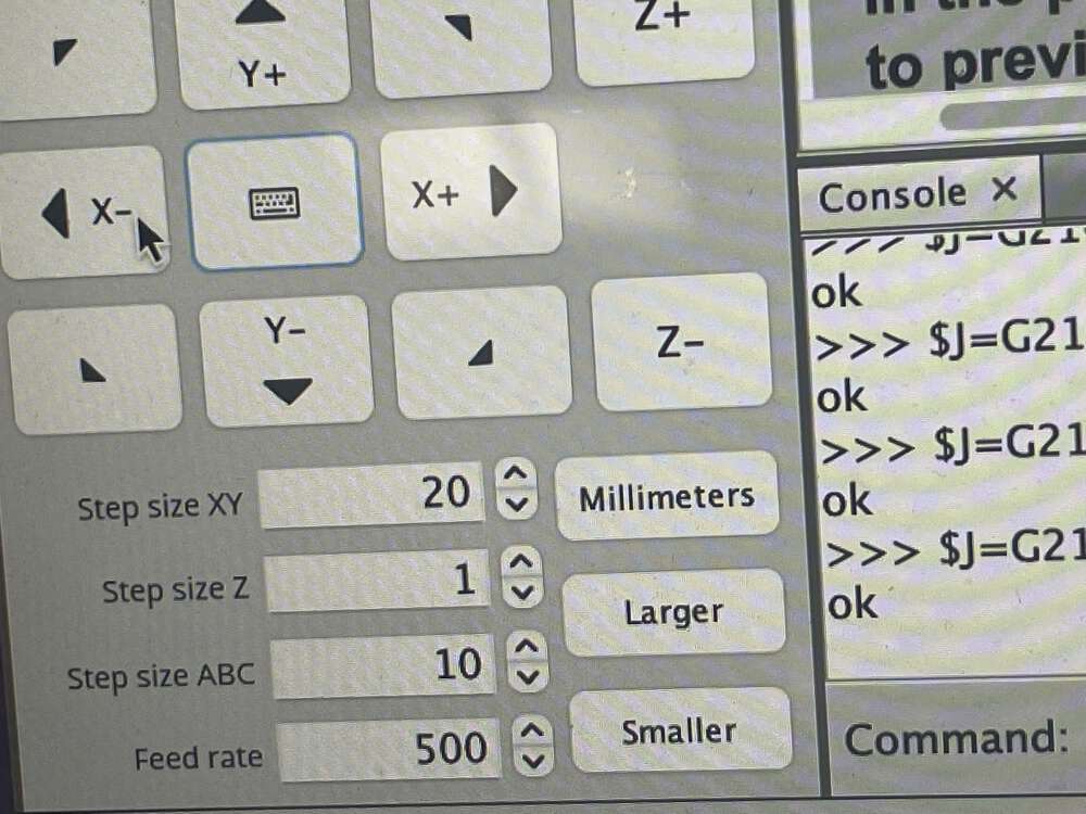
Use the ‘jog controls’ (C) to position your spindle where you want it on the XY plane. Click X0 and Y0 to zero the X and Y (D). A couple of quick notes on the jog controls: if you haven’t used a desktop mill before, moving the Y-axis might be a bit confusing. Y+ moves the bed towards you. Let me repeat: Y+ moves the BED towards you, which allows the endmill in the spindle (which does not move on the y-axis itelf) to access the upper reaches of the y-axis for milling.
All of the other jog controls are relatively intuitive. Also, note that you can change how far the drill moves each time you click on it in the jog dialog box. You always want to be careful about these settings. If the movement is too small, it can take forever to get to where you are going. If it is too large, you can easily hit a limit switch.
For the air test, we won’t actually zero the Z properly since we haven’t yet put in the end mill. Just make sure that you have zeroed the Z so you won’t hit a limit switch.
Next, go ahead and hit the ‘play’ button to see what happens! If it seems like your mill is moving as expected, it is time to move on to actually cutting your traces.
Cutting Traces
First, set up your mill. Make sure you have the correct size end mills on hand (1/32 and 1/64) and begin by installing the 1/64 bit. I find it easiest to take the little bit holder that unscrews from the mill off and to push the bit in and align it with the top of this piece:
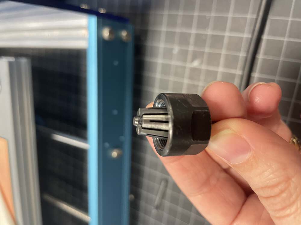
You then begin by tightening the end mill into place by hand. Subsequently, you use the two wrenches to tighten it further, one in each hand. When you tighten your end mill with the wrenches, your hands move apart. When you loosen it, your hands move together.
If you were happy with your X and Y zeroes for the air test, you can keep these as is. However, you will need to re-zero the Z for the 1/64th end mill. If you don’t use an automated approach, zeroing the Z=axis can be a bit of a nuanced process. Having broken an endmill the first time I tried to Zero the Z-axis on my own, I am most comfortable manually sending GCode to turn the spindle on (M03 followed by s10000 for speed 10000). This way, if you hit the board by accident, you don’t risk breaking your end mill.
You can also change the spindle speed here:
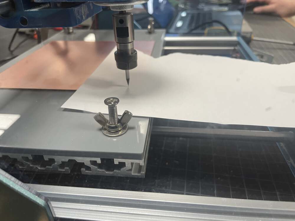
Chris, one of my instructors, showed me a couple of ways to zero the z-axis. My favorite method was the paper test. I prefer to turn on the mill using the gcode shortcut m03 and the s10000 if the spindle doesn’t start right away. You navigate to a part of the board where you are not going to be cutting, place a piece of paper down on the board, and then inch your way down towards the paper until it just breaks the surface. You have to be very attentive to the settings and make sure that you make your movemenets much smaller as you near the material…sometimes even down to 0.05 millimeters. Once you find the location, you zero the Z, bring up the bit using Z+, reset and start the job.
We placed a piece of paper on the board and incrementally lowered the Z until the spindle just cut through the paper. Now that I have done this a few times, I don’t feel like I need the paper as much, though I still use it on occasion.
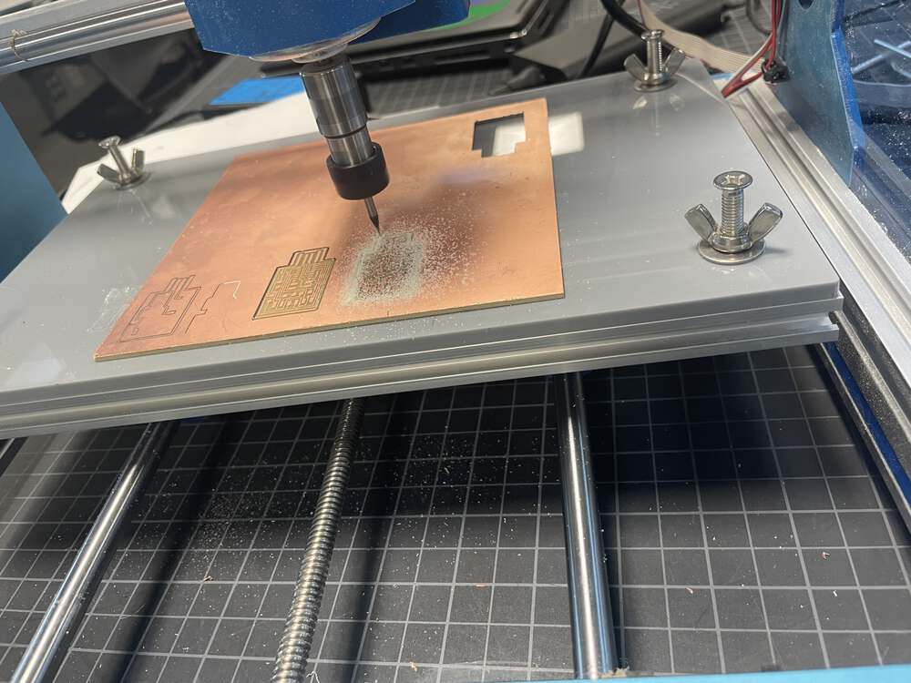
After you zero your Z-axis, you should be good to go – just hit play! It is important to stick around and watch your mill as it runs. In particular, if you start to hear any loud noises, you should hit pause and then stop because something might be wrong and you can easily break a bit. I speak from experience (three times over). It is better to be less aggressive and then run the file again a second time if necessary rather than breaking an endmill.
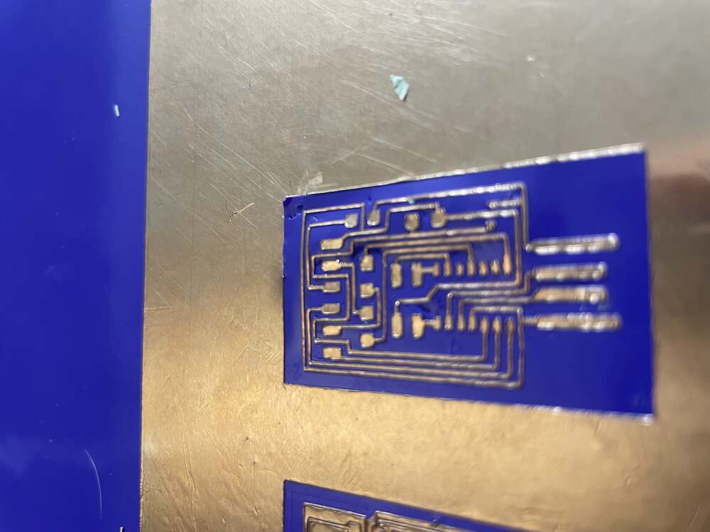
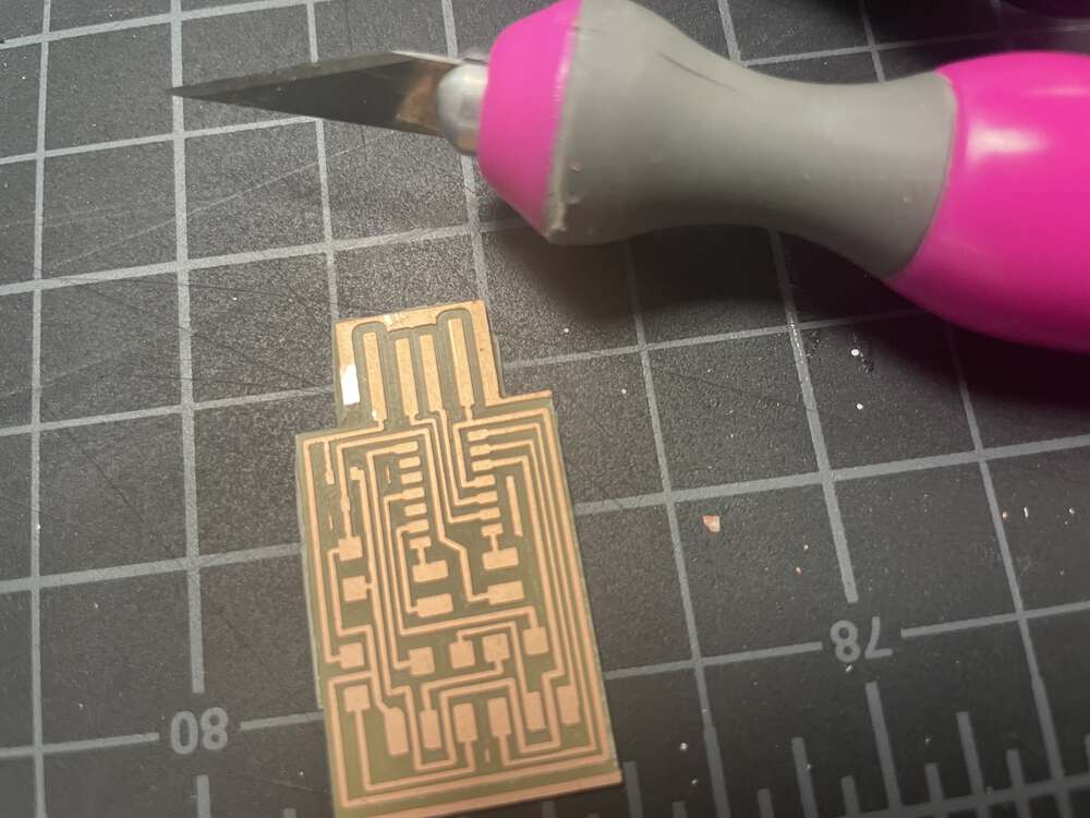
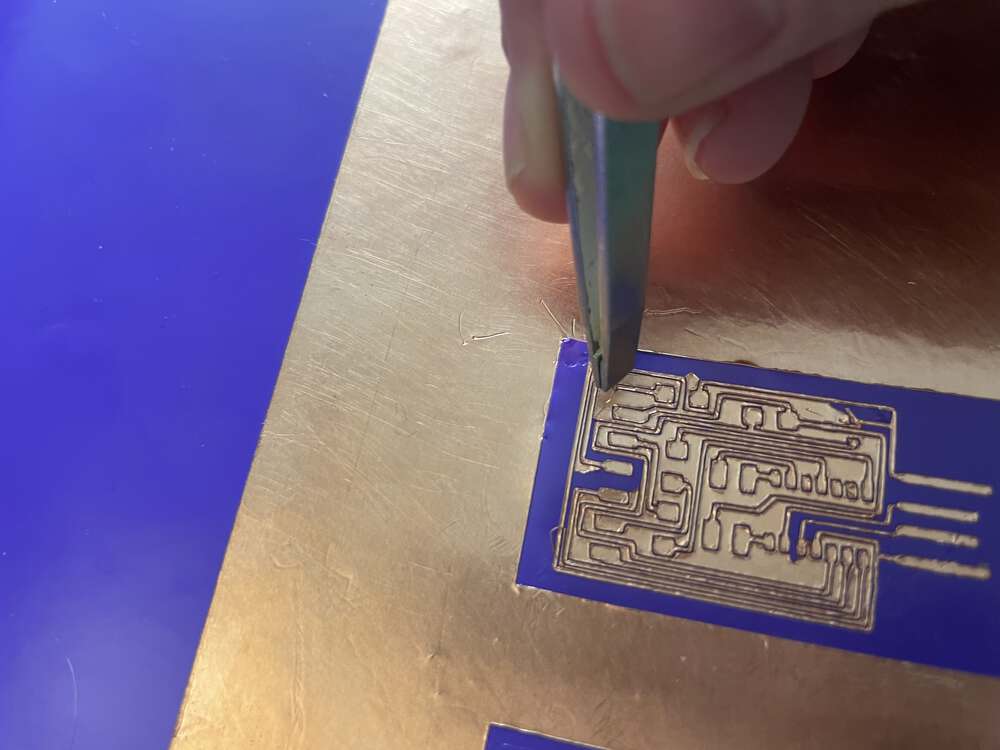
You follow the same basic process to cut the perimeter. You keep the X and Y zero settings, swap out the endmill, reset the Z axis zero setting, upload the new GCode, and cut the file. If all goes well, when you are done, you will have a usb thumb-drive style board with traces milled out. You will still need to clean up the edges and remove the copper with an x-acto knife.
Remove excess copper with x-acto knife:
Stuffing
The soldering tutorial in the student bootcamp was incredibly well done. You can find the slides here and the video here. In addition to defining soldering and going over the tools of the trade, the instructor describes the nuances of different challenges associated with surface-mount soldering as well as potential pitfalls. That said, there is nothing like hands-on instruction, and my LCCC instructor, Chris Rohal, brought me up to speed very quickly. I was amazed to be soldering such tiny components so quickly!
The things that struck me as most significant included using liquid flux and tweezers, and tacking down one side of the component before trying to solder the other side. This was the smallest thing I ever soldered…I actually liked it a lot more than soldering through hole components! Sorry somme of these photos are a bit blurry, I was having a difficult time with the camera autofocus feature for some reason.
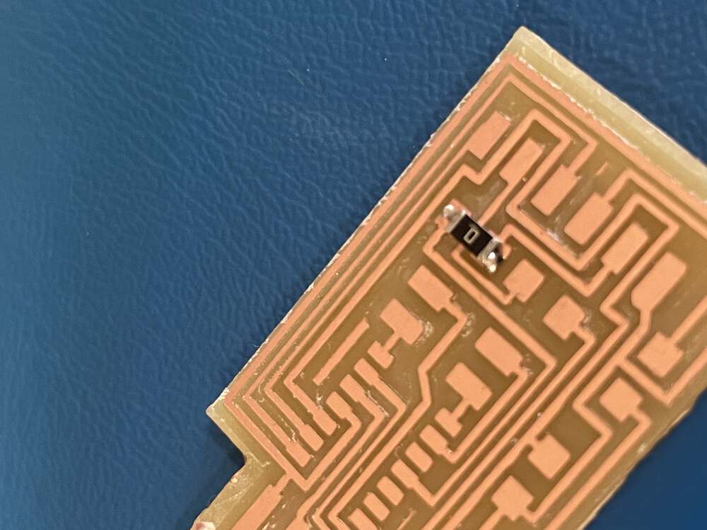
First I tried a zero ohm resistor:
Next I tried the IC, a SAMD11C:
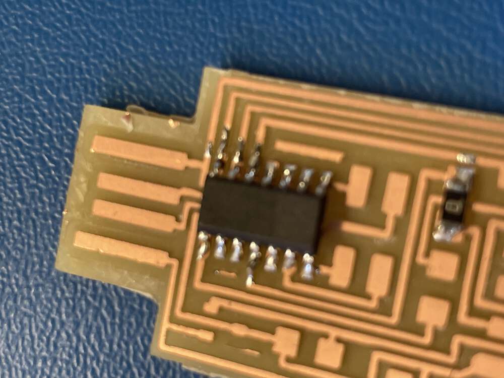
The DIP ICs I have used usually have a nice big circle or notch to help identify pin zero. I eventually found the MINISCULE dot on this thing after a lot of moral support from global open time…but I have to say that I was super grateful that my instructor had told me to look for the beveled edge, which is also on the pin 1 side and is much more noticeable.
Adding a few more connectors:
Here comes the FTDI connection:
EDBG and Installing Arduino Core board manager
At the end of this week’s assignment, our goal is to have created a board that we can use to UPDI program the custom microcontrollers we will be designing for future assignments. I still feel a little bit fuzzy on some of this process, particularly because I did not do a great job documenting it during the semester, but below I will outline what I recall below and seek clarification / confirmation from my instructors.
Normally, we might use an FTDI cable (which functions as a USB to serial converter) to program our Arduino. The UPDI programmers we are building this week replaces the FTDI cable. Eventually, we will use the Arduino IDE and our our homemade UPDI cable to program our custom microctonrollers. However, before we can begin to think about setting up the Arduino IDE to program our custom microcontrollers with our homemade UPDI cable, first we need to program our UPDI programmer. I had a lot of help with this step. I recall that we used an Atmel ICE hardware debugger. I believe we also used EDBG, but that we did so on a Windows machine in the lab because I was having some issues with dependencies on my Mac at the time.
EDBG
EDBG is a software we use on our computer to control microcontrollers. On a Mac, hidapi is a dependency required for EDBG to work. This resource on the Center for Bits and Atoms site shares some walk-throughs for getting EDBG working on different OS.
While my instructor walked me through this process on Windows, for a Mac, you will need to brew install hidapi, for example:
brew install hidapi
You will also need to grab the EDBG code from GitHub, which you can find here.
Follow the instructions from the link above to install EDBG.
Here is a video of my instructor helping me set up my programmer:
Arduino
In order to program our programmers using the Arduino IDE, however, we need to first do a bit of legwork to get our SAMD11c talking to Arduino. You can find detailed instructions about this process in a few locations. I am following these instructions from Quentin as well as these instructions from the Kannai lab. The first step, however, is to install the correct board manager.
Navigate to preferences and find the section of the dialog box dedicated to board manager URLs:
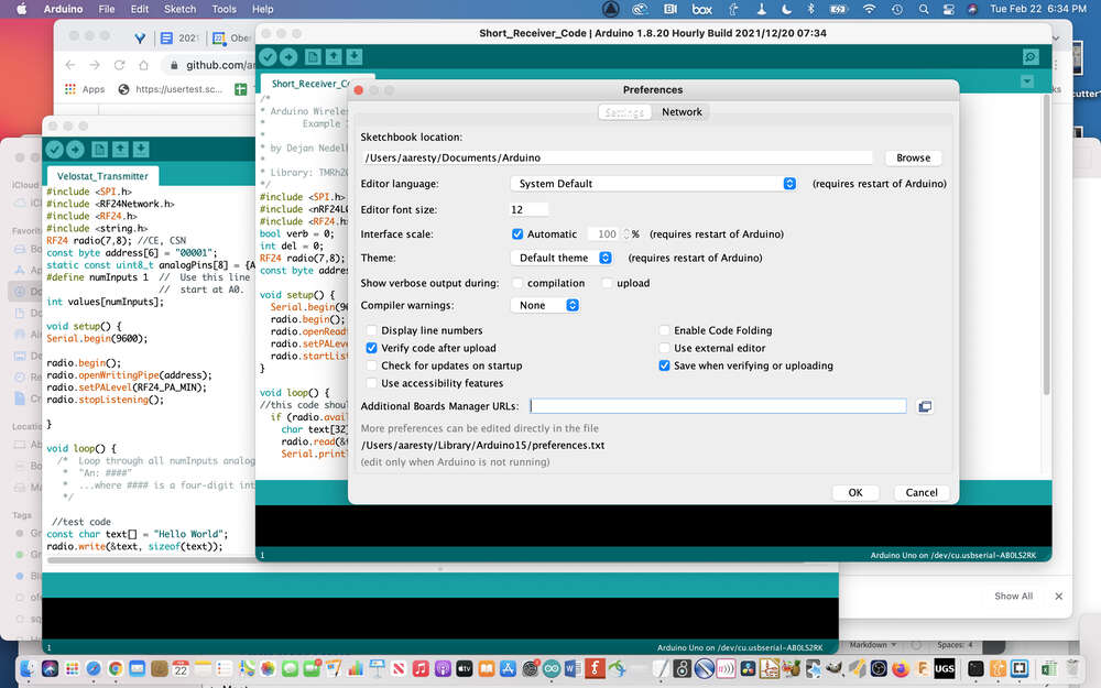
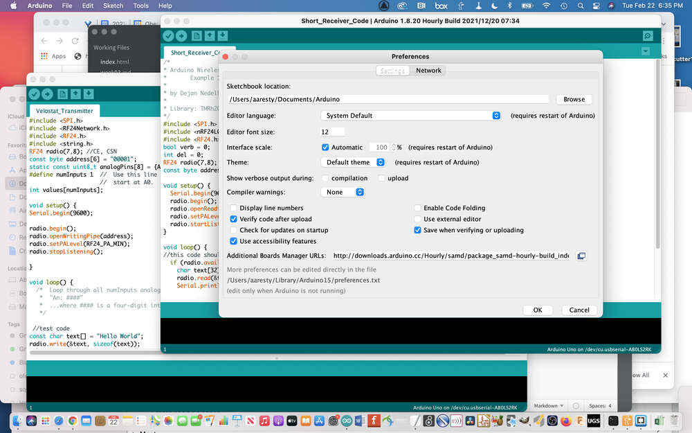
In the dialog that pops up, you will need to add a URL to the correct board manager:
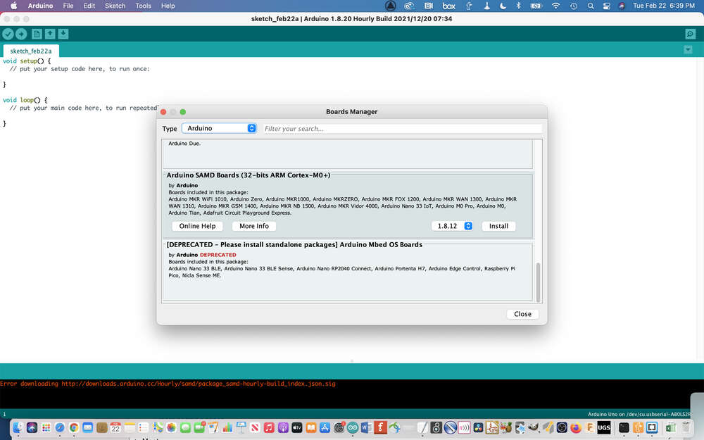
Then, under the ‘tools’ menu, select ‘Board Manager’:
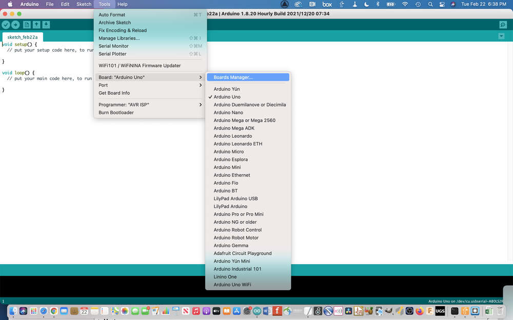
Install the SamD11C board manager:
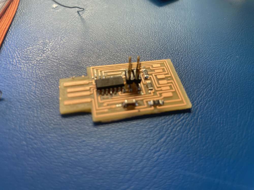
Board Programmed with Programmer
While I was able to mill and solder two programmer boards this week, I did not have the opportunity to test them to ensure that they were functional. During the electronics design week, with the help of my instructor Chris Rohal, I was able to complete this portion of the assignment and confirm that the programmers I built do, in fact, work! You can see the microcontroller I programmed with my DIY board here:
Troubleshooting Electronics Production
Before proceeding further, I wanted to include a few tips about issues I have run into at various points in time while working with this setup. I have run into quite the variety of issues, so I hope this might be of use to someone else (or to my future self).
- G-Code issues: One strange thing we noticed when we opened these GCode files that we had just generated in Mods in the Universal GCode Sender Platform (UGS) was that UGS did not like one particular line of gcode, T1M06, which is near the top of the file. A quick Google search suggests that this GCode is related to a tool change. In any case, it stopped the milling process in its tracks before it had even started. So, I don’t know if this is specific to UGS, but if you run into an error message complaining about T1M06, our workaround was to open the file in a text editor and delete that line of GCode. Everything else ran just fine.

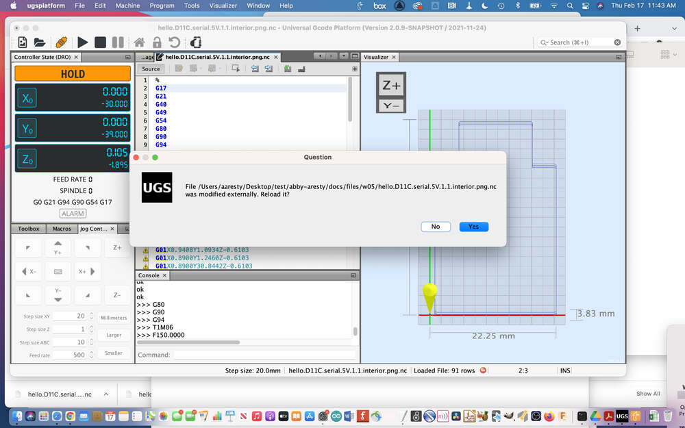
One time, UGS even did me the favor of recognizing that I had edited the file I was using, automatically:
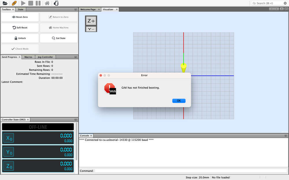
- E-Stop issues: When you click the little plug icon to connect your computer to the mill, if your status says disconnected, you may need to troubleshoot some as I did when I came across the error in the photo below. If you see this, check your emergency stop button! I lost over an hour to troubleshooting after I accidentally pushed in the e-stop button while I was moving my mill around.
-
Arduino issues: The SainSmart mill has an Arduino running the GRBL firmware which allows it to interpret GCode read from a microSD card or sent from a software G-Code sender. Because the machine runs on an Arduino, if you are ever using the machine to program a separate Arduino you have to be exceedingly careful! I accidentally overwrote the GRBL file on the SainSmart Arduino several times when trying to upload code to a different Arduino. Thankfully, you can find the GRBL firmware online and re-upload it to the SainSmart Arduino to solve your problem.
-
Zeroing your Z-axis: One of the trickier tasks when milling can be accurately zeroing your Z-axis. Zero it too high, and nothing will actually get milled. Zero it too low, and you could easily break an endmill. Since you can always re-zero your Z start your project over, the broken endmill is a much worse outcome. So, I have erred on the side of caution. I zero my Z a bit higher than where I think it should go. If I make a mistake, as soon as I start to hear something that sounds a bit louder than I would like, I stop the file, re-zero the Z a bit higher, and start over. I’ve noticed that the boards, spoil layer, or CNC bed are not very level and the higher pass often leaves some copper that should have been milled. So, where necessary, I will re-zero the Z-axis a bit lower and run the fil again. It is a bit cumbersome, but better than breaking endmills! One thing I have not yet tried but really want to explore in the near future is auto-leveling. It seems like auto-leveling would help make the milling results more accurate and save many bits. A few resources for autoleveling PCBs include Marlin, Autoleveller, and ChiliPepper.
-
Hitting a limit switch: At some point, you will likely hit a limit switch. Limit switches are switches that close a circuit when depressed; they are depressed when the endmill is moved by the machine too close to an edge (or x, y, or z ‘limit’) of the machine. When this happens, your machine will make a hard stop. You will lose any previous zeroing. You may also have some difficulty getting the machine to move again. When this happens to me, I move the machine manually until the limit switch is no longer activated. Then, I hit the ‘soft reset’ and ‘unlock’ buttons in sequence several times. I attempt to use the jog controls after each time. Eventually, this unlocks the machine and I am able to proceed. Here is a video that might help if you run into this issue.
Bonus: Vinyl Cut Circuit Process
I was very curious to experiment with cutting copper tape traces for the programmer. I had cut copper tape traces previously, but I was never previously able to cut the thin traces I first saw in Fab Academy because I always tried to cut the copper tape directly on its original backing. The backing material that copper tape is sold on has poor adhesion so that it is easy to remove the tape. If you try to cut the copper tape in your vinyl cutter usng this backing, it may work sometimes, but fine details will likely be lost when the material comes up from its backing. Below, I walk through the process of cutting the copper tape traces. I did not try to solder this programmer. If you would like to see an example of soldering to copper tape traces, I will be updating my electronics design week with documentation of my KiCAD design and fabrication of an astable multivibrator.
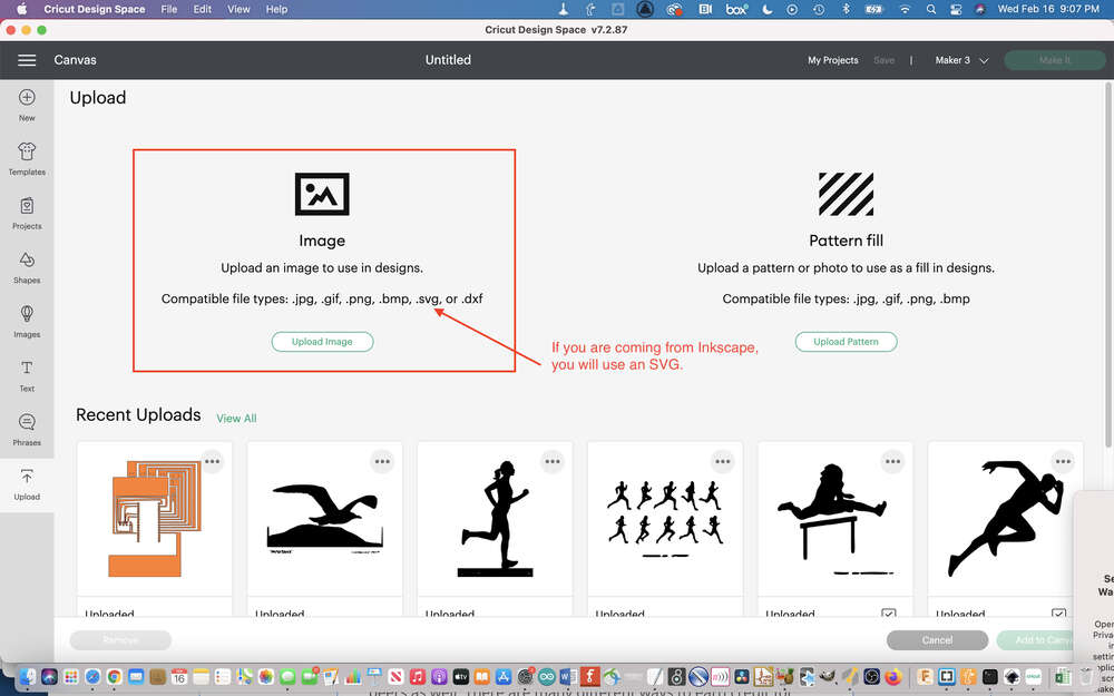
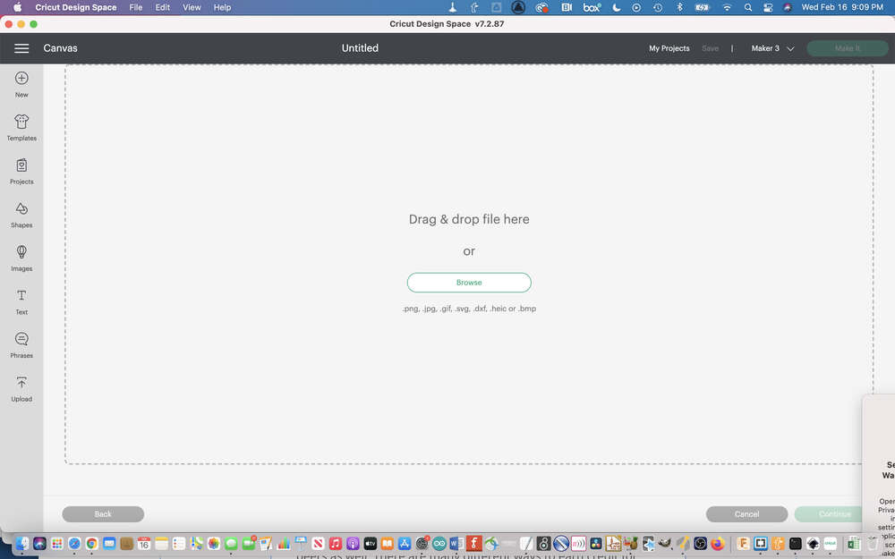
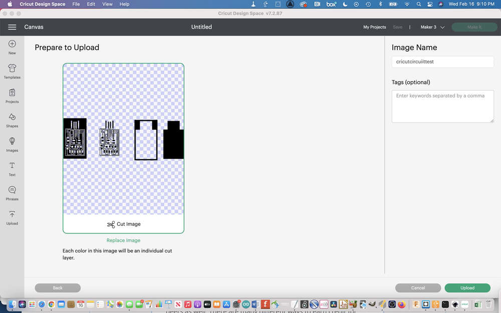
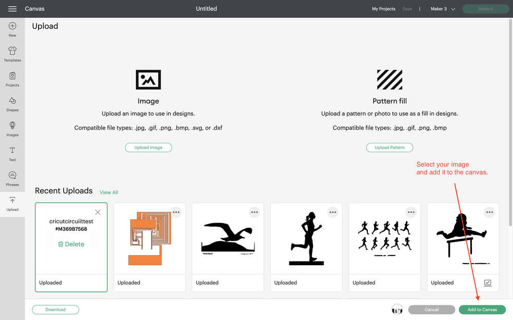
To begin the vinyl cutting process, you need a file to cut. For this experiment, I used the same SAMD11c programmer design provided by Fab Academy that I previously milled. Once you have an SVG file you should import it into the Cricut design software and import it into the workspace for your project.
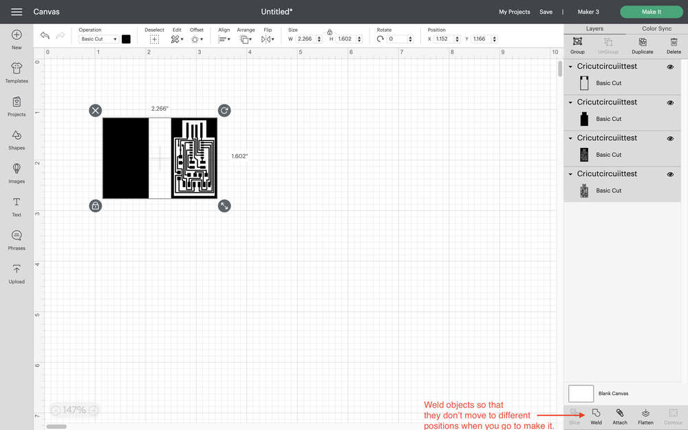
When your design is ready you can import it into the Cricut software:
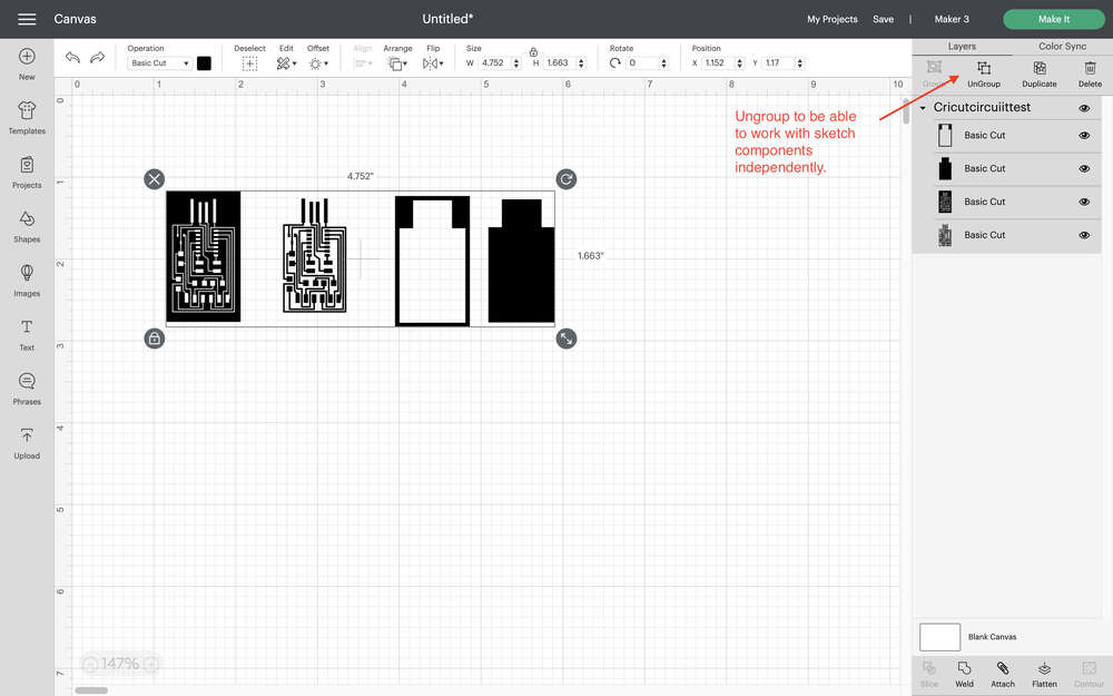
You may find that you want to ungroup some of the objects that you have imported in order to make further edits in the Cricut Design Space software.
When you are ready to cut your image you should select the “Make it” option. However, you will find that while your design might look accurate in the design workspace workspace, when you try to cut it, different portions of the image that you have imported sometimes end up in unexpected locations. To fix this you will need to go back to your design workspace and select “weld” to ensure that your objects stay in their desired location when it is time to cut.
At this point, if you haven’t already, it is a good moment to prepare your materials for cutting. If you are using a Cricut machine, you will find that you typically will need to use a mat that for all cuts unless you are working with a proprietary smart Cricut material. As of this writing, in general, the Cameo is a bit more flexible, and that you can use any 12 x 12 sheet of vinyl without a mat. There are many different types of mats. You can find mats that are different sizes, as well as mats with different levels of stickiness that are suited to different material types. You will want to begin by choosing the correct mat for you material, and then laying down the material according to where you have placed your design in software. In general it is useful to align material and software designs to the left corner. If you are cutting a special material like copper tape, you will find that you need to transfer the tape to the material you would like to ultimately have the tape on. This is because the backing that the tape comes on originally has very poor adhesion, and as your vinyl cutter cut the tape if it is on its original packing the blade will pick up the tape as you go.
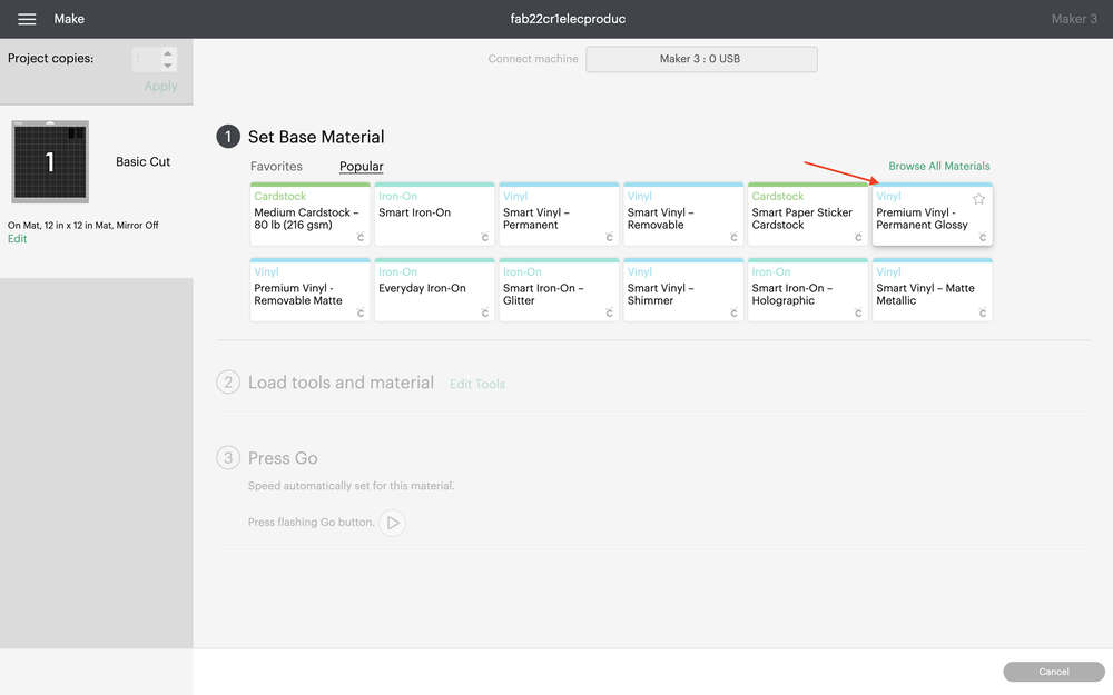
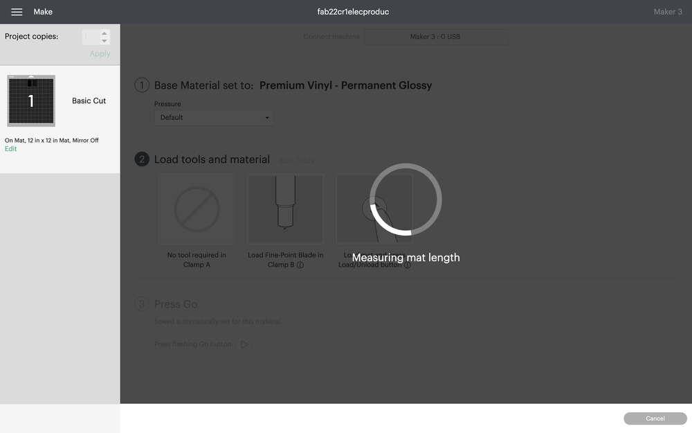
Once you have placed the material you want to cut on the mat you loaded into the vinyl cutter. Turn on the machine and make sure that it is connected to your computer. In the software you will need to indicate the material you are cutting. Copper tape can be cut on a standard vinyl setting. After you have chosen the cutting material in software, you will be asked to press the button on the machine which will load the material into the machine and measure it before the cutting begins.
After you cut the vinyl or other material you can remove the material from the machine and the mat. The process that occurs next is weeding the vinyl. To weed the vinyl you remove the excess material that you do not want to have included in your design. Next you use clear transfer tape to pick up the design as you want to transfer it and to place it onto a new substrate. Throughout the weeding process, it is important to ensure that you are only removing materials that you would like to remove. When transferring the material to a new substrate you will want to ensure that you check that the material as level and use an ID card or other hard surface to help lay down the vinyl and ensure that it sticks onto the new surface.
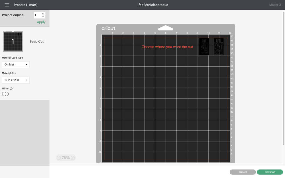
You will be prompted to place materials virtually on mat to determine where they will cut:
You will need to choose your material type - I typically choose vinyl:
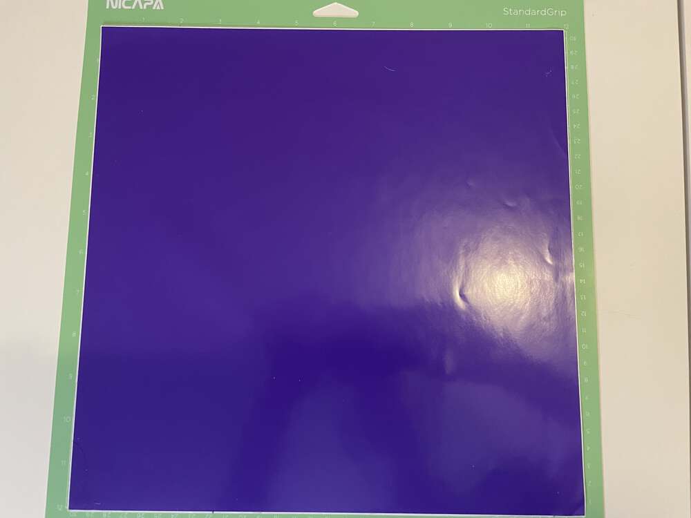
In this case, before I cut the copper traces, I wanted to try the file on a less expensive material. Now is a good time to make sure your materials are ready to go if you have not done so already. I prepared the material by sticking it to a Cricut mat:
Next, you will be prompted to select whether you are using a mat or not:
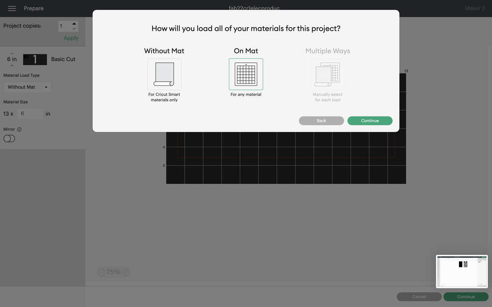
Then, you will be prompted to load your material into the Cricut:
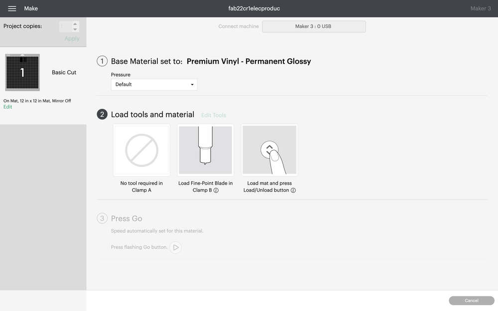
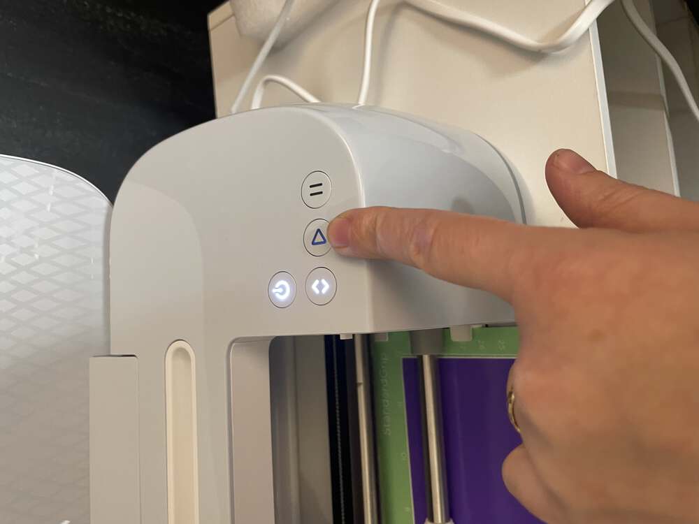
And press go!
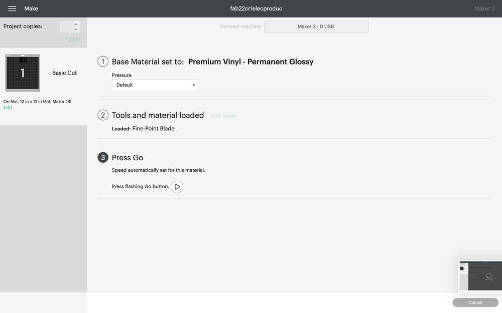
You will need to click on the ‘play’ button or the ‘Cricut’ button to actually start the cut:
 The Cricut will automatically measure your mat length:
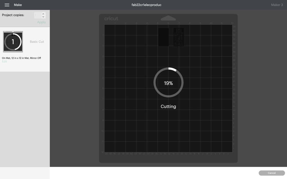
While the machine works, the computer software will indicate the percentage completed of the current cut:
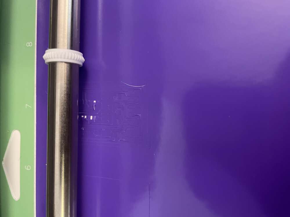
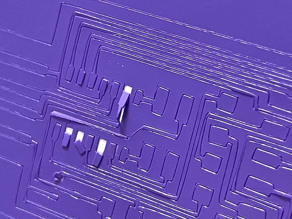
Here you can see a photo of the vinyl cutter midway through cutting the vinyl. It is already running into issues because the adhesive backing on the vinyl is not strong enough to facilitate such an intricate cut:
The results are not 100% transferable to cutting the copper tape, since the materials may have different strengths or thicknesses, however, you will still gather useful information about your cut. I was a bit concerned, initially, about these results:
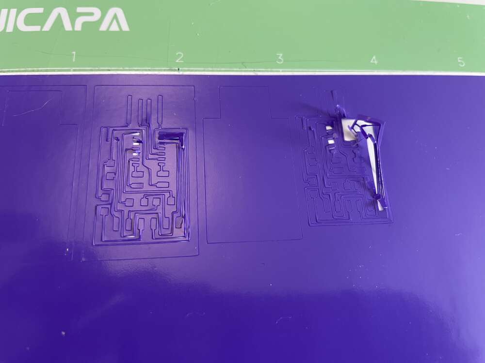 Below you can see the imperfect results a bit more clearly:
 When you are ready to try the copper, cut a piece to size:
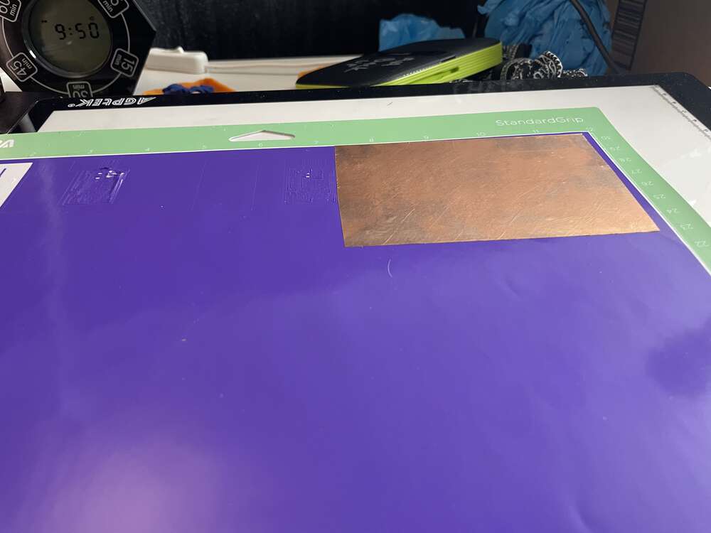
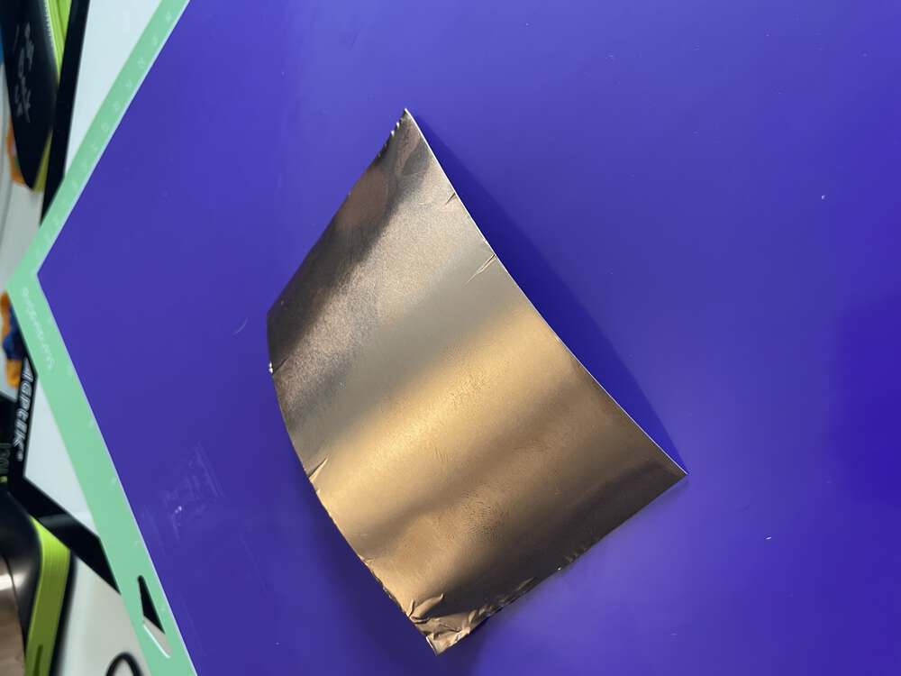 And affix it to your chosen substrate. I recommend using either Kapton tape or Epoxy film. Vinyl is less than ideal, but it is what I had on hand for testing:
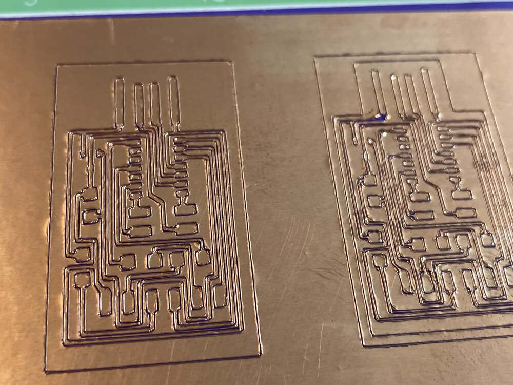
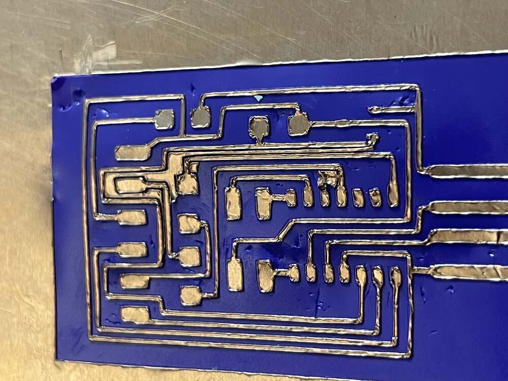
 I was impressed by how well the traces came out. The copper tape cut extremely well when adhered to a substrate other than its original backing:
 I then began the weeding process:
 Weeding the copper tape traces took a very long time. The vinyl was not the best material for a substrate as it was easily damaged.
But I did finally finish weeding one of the traces!