13. Input Devices
Our Homework this week:
The second half of the Fab Academy programme is designed to build on the previous weeks. You will be synthesising information and implementing skills that you were introduced to in the first half of the programme and encouraged to integrate these into your final project proposal.
Our assignment this week is to:
Group assignment:
Probe an input device(s)’s analog and digital signals Document your work to the group work page and reflect on your individual page what you learned
Individual assignment:
Measure something: add a sensor to a microcontroller board that you have designed and read it.
Learning outcomes
Demonstrate workflows used in sensing something with input device(s) and MCU board
Have you answered these questions?
Linked to the group assignment page Documented what you learned from interfacing an input device(s) to microcontroller and how the physical property relates to the measured results Documented your design and fabrication process or linked to previous examples. Explained the programming process/es you used Explained problems and how you fixed them Included original design files and source code Included a ‘hero shot/video’ of your board
What is a Sensor?
A sensor is an electronic device that measures some property in the physical world. When connected to the input of a microcontroller, sensors allow us to tap into data from the outside world and read that data on a computer, or else map it to a desired software or hardware output. Different sensors measure different types of physical properties, and do so in different ways.
One of the simplest kinds of sensors is a pushbutton. A pushbutton can be placed in a circuit’s path to interrupt the flow of electrons. Let’s imagine a simple circuit with a battery, a resistor, and LED, and a pushbutton. A pushbutton that is ‘normally open,’ will ensure that we don’t waste any battery, because the circuit will always be ‘open’ or off until we press the button, closing the circuit and turning on the light. Of course, as you might have guessed, there are also buttons that are normally closed, that only turn off the circuit when pressed. In this case, we might run through our battery a bit too quickly if we used a normally closed pushbutton. If you hook up a push button to an microcontroller, the microcontroller can sense when the pushbutton is pressed and when it is not. Since the pushbutton only has two states, open and closed, it is a digital rather than analog sensor and we can hook it up to one of the microcontroller’s digital pins.
So, a pushbutton is a type of switch, as it turns a circuit on and off. But it is a momentary switch: it toggles back to its original state as soon as you release it. We encounter a lot of pushbuttons and switches in our daily lives, so these types of sensors are familiar and intuitive, at least in their most basic forms. The switch you use to turn your lights on and off is often – though not always! – a toggle switch. Unlike a push button, a toggle switch holds its state unless you mechanically switch it back yourself.
You can get a lot more mileage out of the simple on/off than you might imagine at first glance. There are lots of different types of sensors that are just more or less fancy switches. For example, a magnetic reed switch opens or closes based on the proximity of a magnetic field. A small metal reed embedded in glass moves when you place a magnet near the switch. A tilt sensor is a switch that opens or closes depending on how the sensor is tilted. These sensors used to house mercury that would physically move around the sensor, either connecting two leads or not based on the orienation of the switch. These days, safer materials are used the same way, like a small metal ball. There are many more types of switches, controlled by different types of inputs, including electrons! Some electronic components like transistors open and close based on whether they are receiving any current at a specific terminal. You can think of it like someone knocking on a door…when the transistor senses someone knocking, they either open up the door and let electrons through or slam it shut. Note that this analogy is far from perfect, but I still think it is useful to get the general concept across!
Thus far, we have been talking about a fairly simple category of switches. All of the different switches we have discussed are ‘single pole, single throw’. What that means is that the switches only control a single circuit, and they only toggle between two positions: on and off. Double pole switches control two circuits; double throw switches have three mechanical positions – up, center, down – two of which will share the same state, either on or off. Switches can get more complicated still, but for now, I will leave it there.
If you would like to read more about switches, I found this resource very useful. I also appreciated this resource which provides a really quick clarification about poles and throws.
Sensor Types to Explore and Define
- Switch
- Magnetic Field
- Potentiometer
- Step response
- Temperature
- Light
- Motion
- Distance
- Location / Time
- Acceleration / Orientation / Rotation
- Sound
- Vibration
- Force
- Angle
- Pressure
- Pulse
- Air pollution
- Gases
- Image
Step Response
I was really excited to explore the concept of step response sensors because I am very interested in craft-based electronics and work a lot with copper tape and copper fabric. I’ve experimented with capacitive sensors before and have run into many of the usual interference problems. I wanted to better understand how step response works and why we are calling these sensors step response sensors. I did some googling, initially, but found that it was actually most effective to ask a series of clarifying questions to ChatGPT.
First, what is meant by step response?
To paraphrase both ChatGPT and also a range of other sources turned up by a quick google search (Khan Academy, Wikipedia, etc.): step response describes how a system behaves in response to a sudden change to its input. Sources described how systems will often have a fleeting or ‘transient’ response to a sudden change before they settle down. This transient response to the sudden input change is the system’s step response.
This is all well and good, but how does this specifically apply to the DIY sensors Neil described in class? Initially when I asked ChatGPT about step response sensors, it discussed a very wide range of sensor types. Subsequently, I decided to start to explore some of the specific code and examples provided to see if I could better understand the relationship between the theoretical concept of step response and the application represented by the sensors. This proved to be a much more fruitful line of inquiry. Specifically, I asked about this code from Adrian’s site:
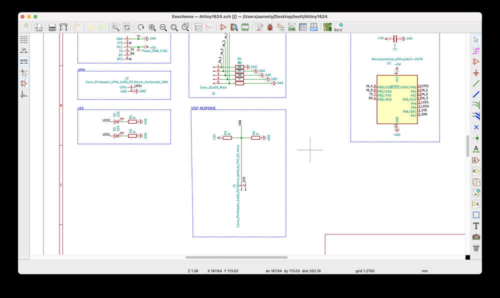
’‘’ //tx_rx03 Robert Hart Mar 2019. //https://roberthart56.github.io/SCFAB/SC_lab/Sensors/tx_rx_sensors/index.html
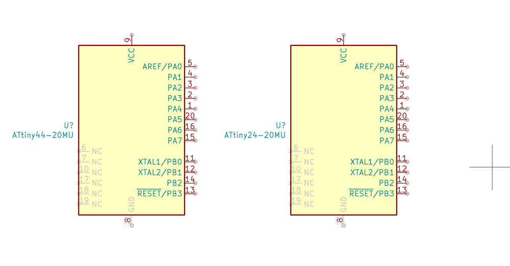
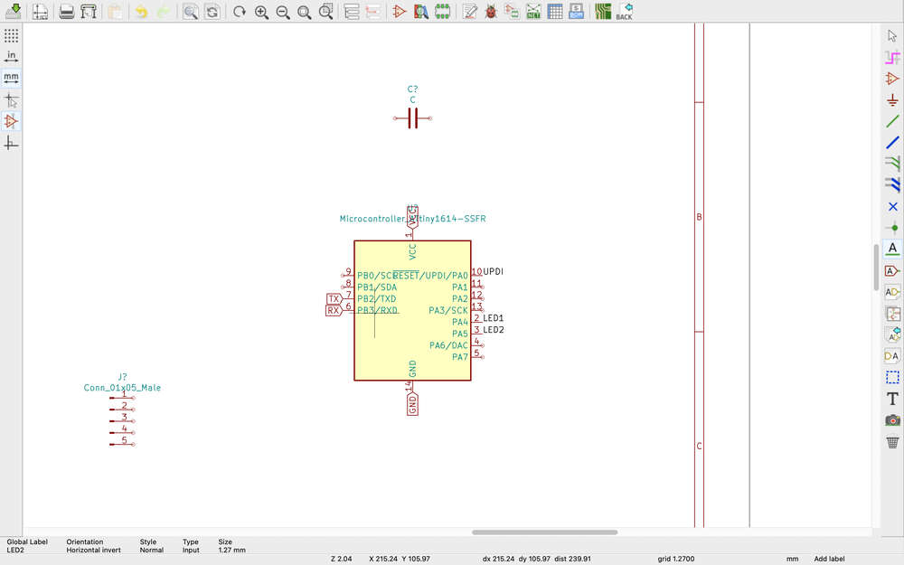
//Modified by Adrián Torres Omaña //Fab Academy 2021 //Step Response TX, RX //Adrianino //ATtiny1614 - ATtiny1624
// Program to use transmit-receive across space between two conductors. // One conductor attached to digital pin, another to analog pin. // // This program has a function “tx_rx() which returns the value in a long integer. // // Optionally, two resistors (1 MOhm or greater) can be placed between 5V and GND, with // the signal connected between them so that the steady-state voltage is 2.5 Volts. // // Signal varies with electric field coupling between conductors, and can // be used to measure many things related to position, overlap, and intervening material // between the two conductors. //
long result; //variable for the result of the tx_rx measurement. int analog_pin = 1; // PA5 of the ATtiny1614 int tx_pin = 2; // PA6 of the ATtiny1614 void setup() { pinMode(tx_pin,OUTPUT); //Pin 2 provides the voltage step Serial.begin(115200); }
long tx_rx(){ //Function to execute rx_tx algorithm and return a value //that depends on coupling of two electrodes. //Value returned is a long integer. int read_high; int read_low; int diff; long int sum; int N_samples = 100; //Number of samples to take. Larger number slows it down, but reduces scatter.
sum = 0;
for (int i = 0; i < N_samples; i++){ digitalWrite(tx_pin,HIGH); //Step the voltage high on conductor 1. read_high = analogRead(analog_pin); //Measure response of conductor 2. delayMicroseconds(100); //Delay to reach steady state. digitalWrite(tx_pin,LOW); //Step the voltage to zero on conductor 1. read_low = analogRead(analog_pin); //Measure response of conductor 2. diff = read_high - read_low; //desired answer is the difference between high and low. sum += diff; //Sums up N_samples of these measurements. } return sum; } //End of tx_rx function.
void loop() {
result = tx_rx(); result = map(result, 8000, 11000, 0, 1024); //I recommend mapping the values of the two copper plates, it will depend on their size Serial.println(result); delay(100); } ‘’‘
ChatGPT explained that this code uses the step response of a system to measure the ‘electric field coupling’ between two conductors. Basically, you attach the tx (transmit) electrode to a digital pin that is alternately outputting high and low voltage. This charges and discharges the electrode, changing the electric field between the two electrodes. You connect the rx (receive) electrode to an analog input pin. When the electric field around the rx electrode changes, this creates a blip in the electrode that is measured by the Arduino’s analog to digital converter. The difference in the values read by the analog input pin from when the transmit pin sends a high vs. a low voltage indicates the level of coupling between the two electrodes. The level of coupling is impacted by the proximity of the electrodes and the material separating them, among other things.
I found the code above on Adrian’s site. I also clicked through to follow the tutorial Adrian was following, by Robert Hart:
https://roberthart56.github.io/SCFAB/SC_lab/Sensors/tx_rx_sensors/index.html
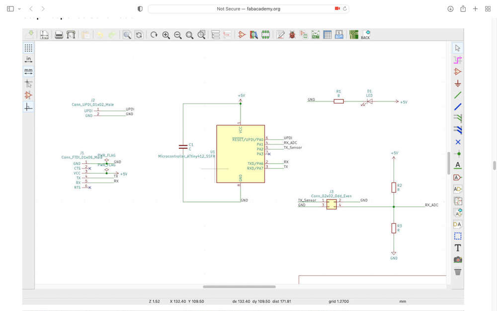
Given my past experiences with less-than-reliable capacitive sensing systems, I was particularly interested in the diagram illustrating the voltage divider implemented between power and ground on this page. It is described as assisting with the stability of the sensor readings. While the two M Ohm (or larger) resistors are said to be optional, in my book, anything that makes your signal more stable should be implemented wherever possible.
To further define:
Dielectric Insulating Capacitance Voltage divider
E-textile Buttons and Switches
Pressure Sensors
In addition to these creative takes on the traditional switch
Let’s say we want to get a bit more nuanced.
in diff
ome aspect of its
Some Links for working with ATTINY1614 or 1624 and Arduino IDE
- https://create.arduino.cc/projecthub/john-bradnam/using-the-new-attiny-processors-with-arduino-ide-612185 Note that we are using our own custom programmer and not an arduino nano.
- https://github.com/SpenceKonde/megaTinyCore
-https://github.com/SpenceKonde/ATTinyCore
Background
I first began working on this assignment during Fab Academy but did not have time to get too far. In addition to making / using sensors, I wanted to take the opportunity to dig a bit deeper into some of the design affordances of KiCAD. For example, I wanted to explore using different shapes for the edge cut / outline. I also wanted to try creating a via. I’d love to incorporate some sort of text or design on the PCB, too, though this is definitely a bonus. I might share bits and pieces from different versions / iterations of input boards because I have been circling back on this over time.
Sensor Types
Overview of sensor types outlined by Neil:
Over the summer, I had a grant to work with a former student on a few projects. One of the projects we began working on was fabricating several of the e-textile sensors originally created by Kobakant. The goal of this project was primarily for use as a teaching tool. This last semester, when I taught a mixed media circuits class and invited students to create their own sensors, students newer to electronics really struggled. These e-textiles sensors are nice because they help to make the functionality of sensors visible and tangible. Most contemporary sensors are tiny and opaque. There form has nothing to do with their functionality.
Links to sensors:
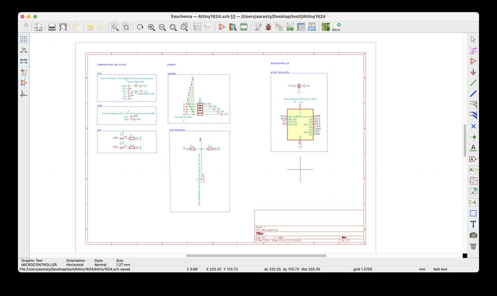
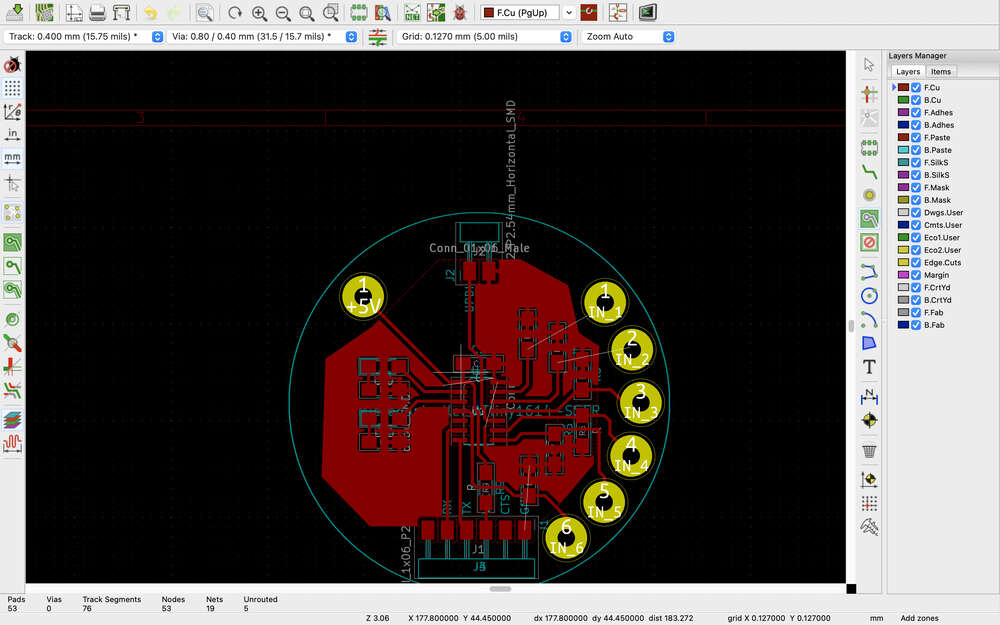
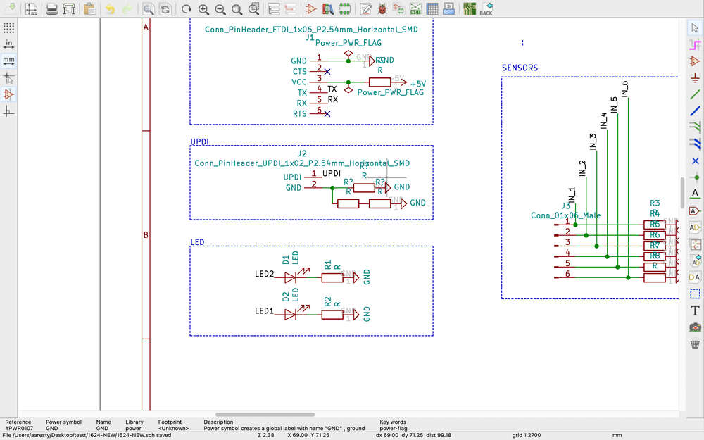
Designing a Board
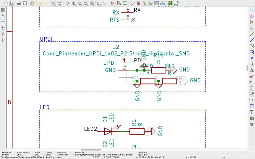
KiCAD
UGS
Milling
Stuffing
Making Sensors
Bonus: Fab technologies in action!
One of the reasons I fell behind on Fab Academy during the semester was because I was working on several creative projects that had hard deadlines. I actually made use of all of the skills that I developed during Fab Academy for these projects. For example, I was working in collaboration with folks to create interactive dance technology that allowed dancers to control sound from the stage. We created sensor boards with magnetic connections and e-textile pressure-sensitive sensors. I came up with the original concept/design for the technology, but a colleague and some students fabricated the e-textile portion of the technology, while I fabricated the large tabletop boards with magnets and the circuit boards, which were breakout boards for an Arduino nano.
ADD PHOTOS
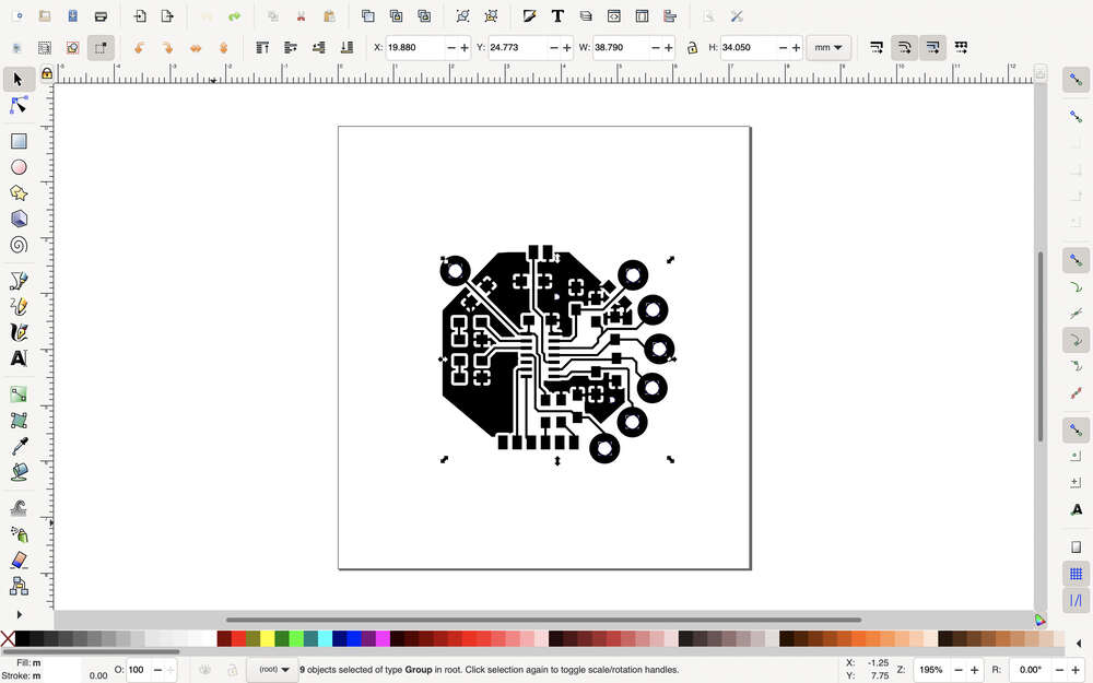
This week I really want to start making my circuit boards a bit more interesting. I discovered this presentationthat covers an extension in Inkscape that lets you assign artwork to different layers of your PCB.
To install…download and unzip, open inkscape and go to preferences and then system support to get the file location where you will put the plugin.
Watching this tutorial: https://www.youtube.com/watch?v=w7fjlV2Mmng I could not figure out how he was getting the menu to move an object to a different layer from clicking…it is option right click on a Mac.
/Users/aaresty/Library/Application Support/org.inkscape.Inkscape/config/inkscape/preferences.xml
I am getting some errors with the Inkscape extension. Here is a different video about graphics, but it is unclear how to go about dealing with edgecuts: https://www.youtube.com/watch?v=w_7iRCyau7w
Part of me is wondering whether I should make the board first and then just add the edgecut in inkscape after the fact.
Ultimately, I discovered that for my purposes, I could just create a dxf file and import it as a graphic on the edgecut layer directly in Inkscape. I imagine if I were trying to do something much more complex with more layers that the Inkscape extension might be more useful.
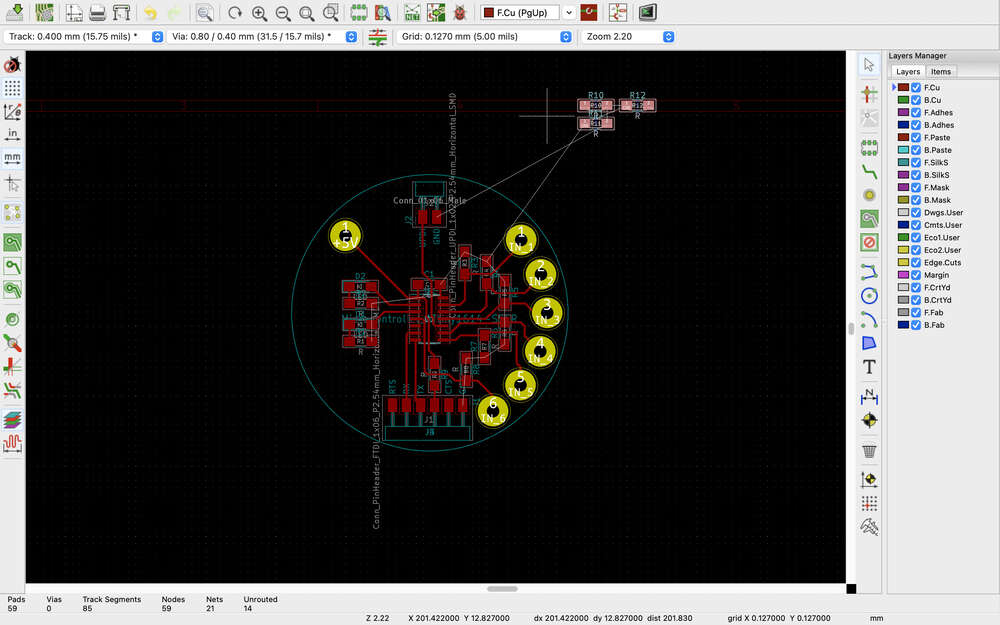
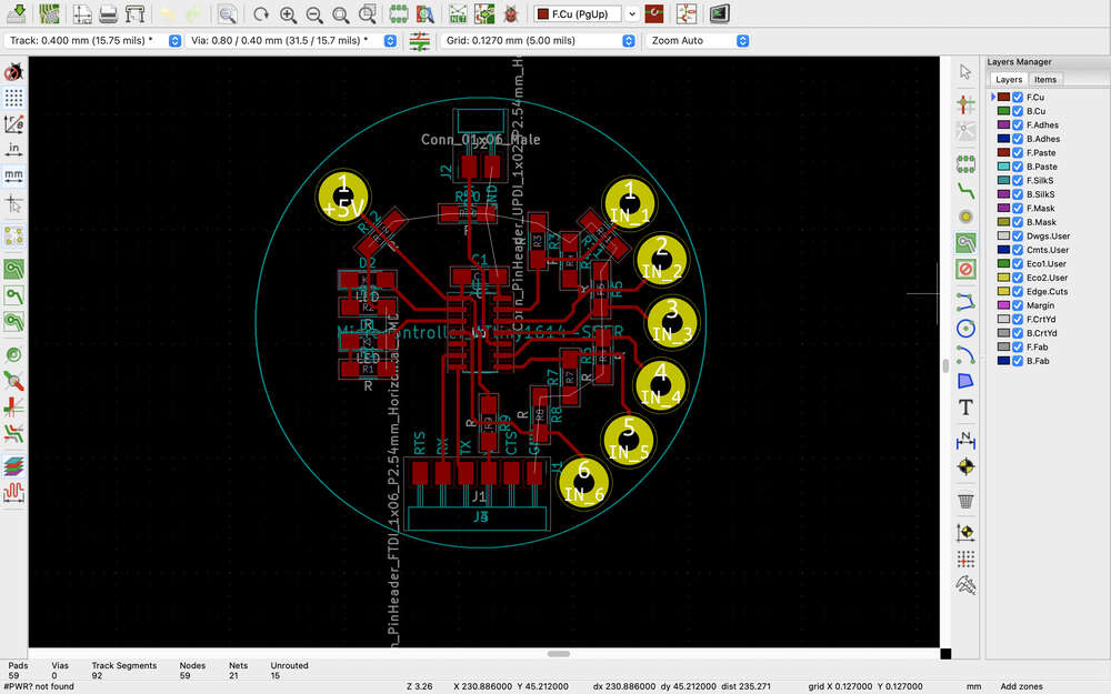
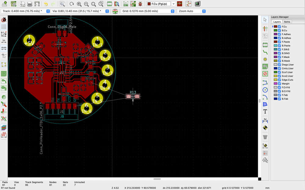
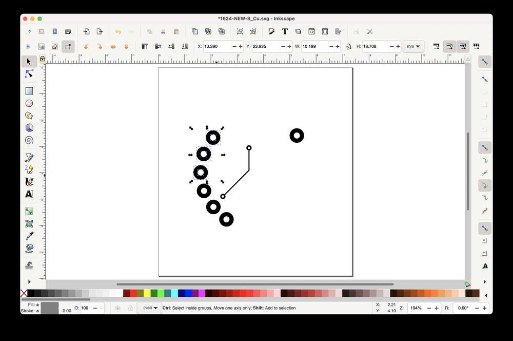
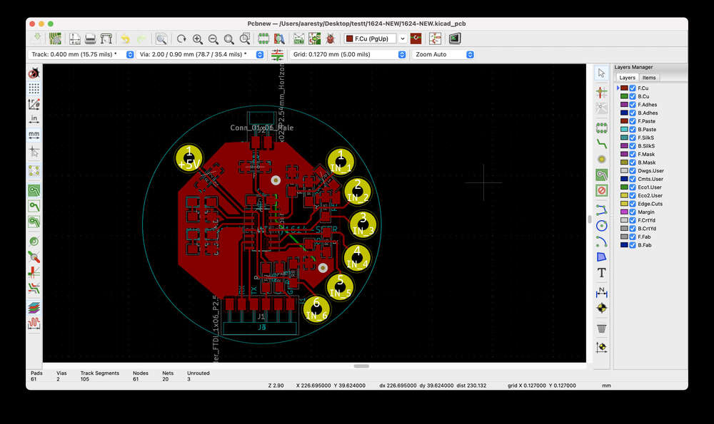
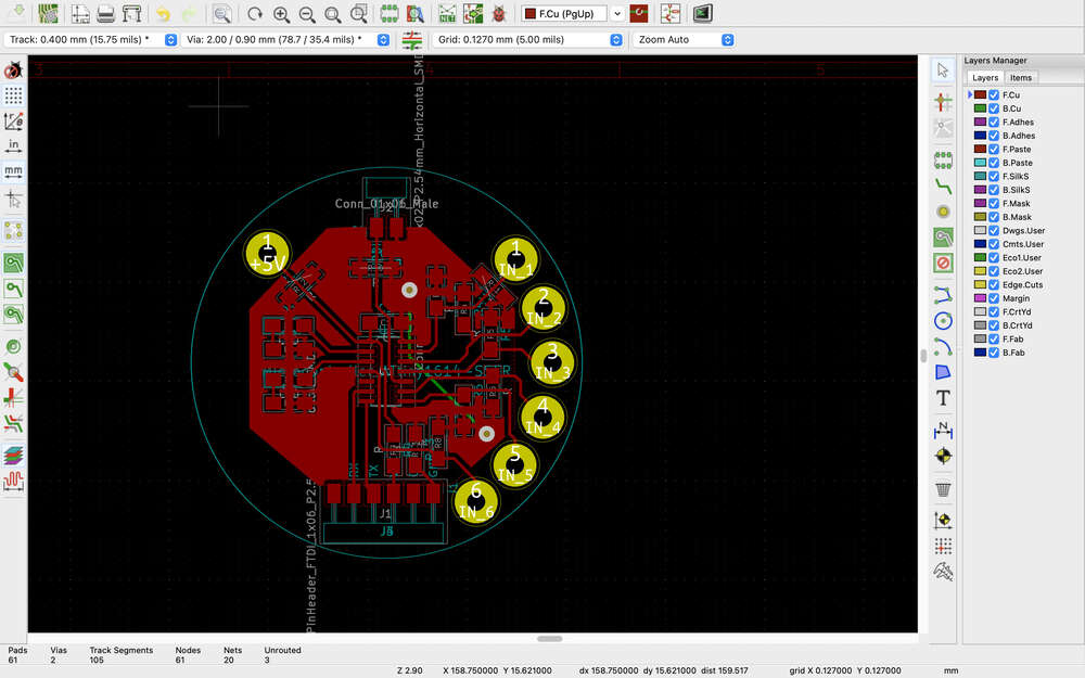
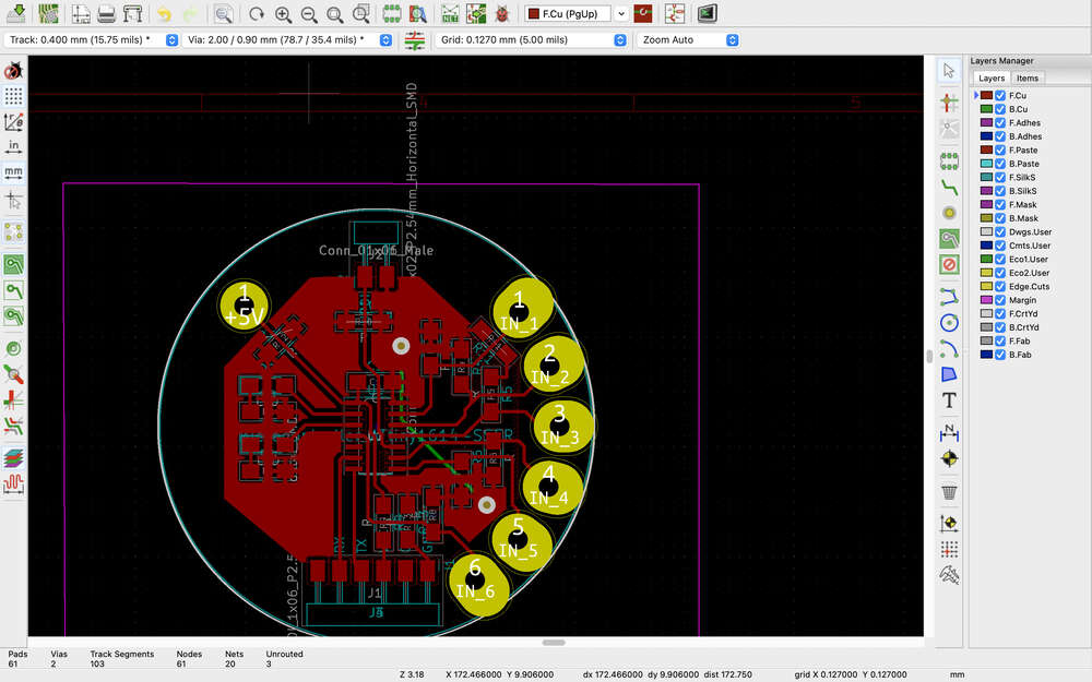
Vias
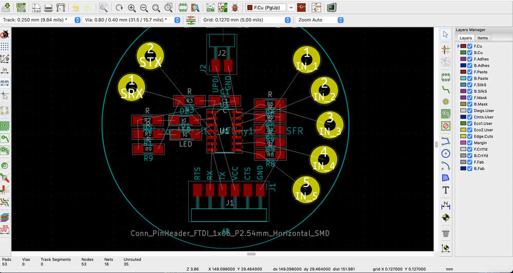
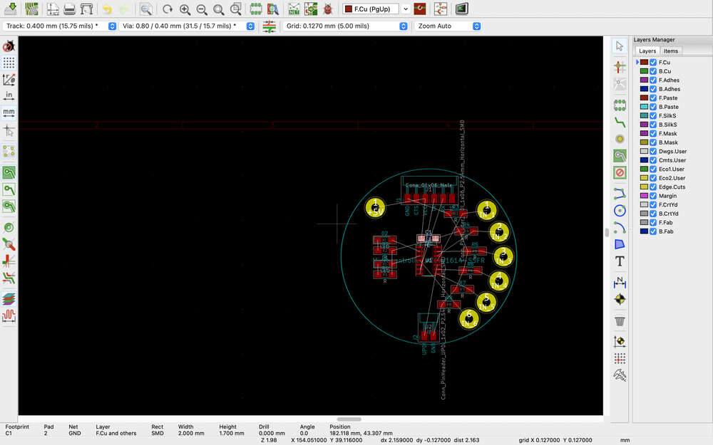
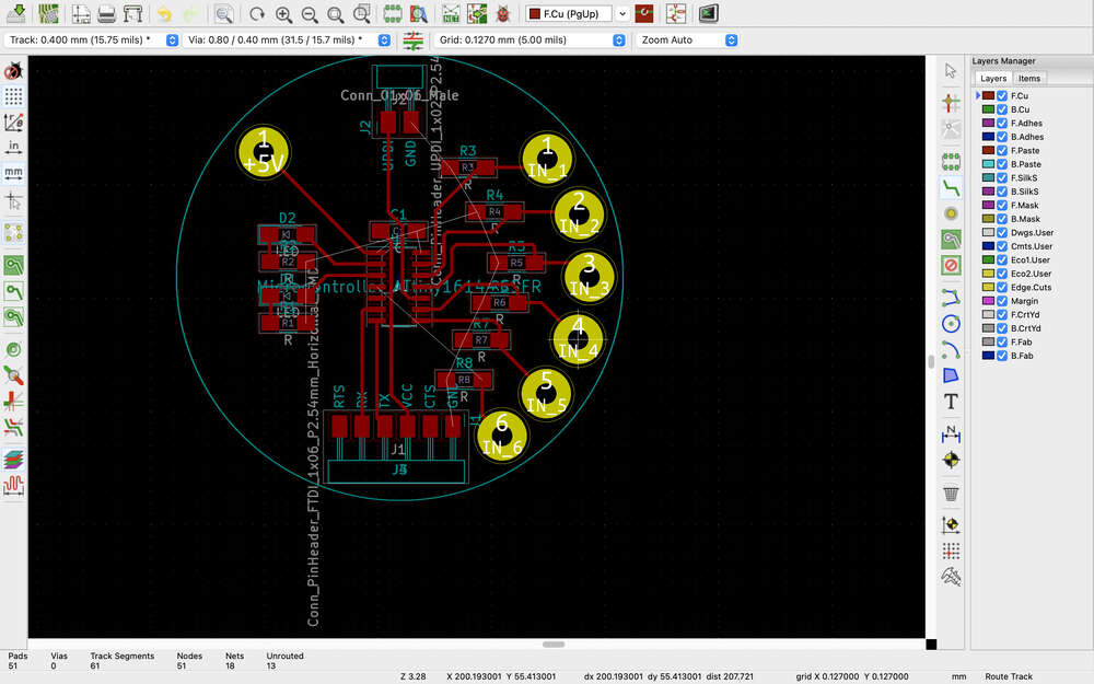
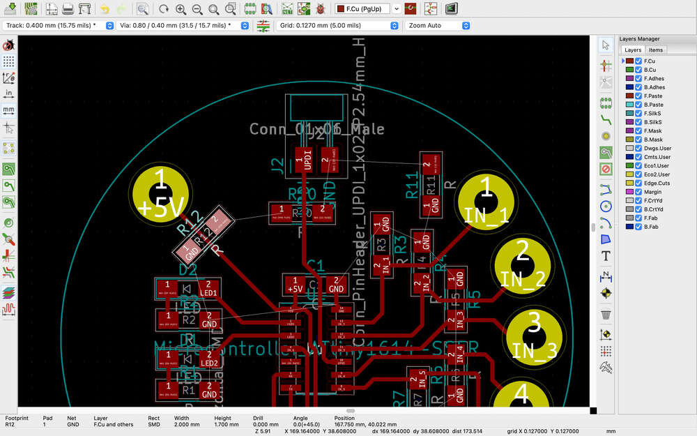
Somehow this time around my board had so much stuff on it that it seemed really difficult to figure out how to get the board routed on a single side. Since I have some double-sided PCBs, I decided it was worth experimenting with vias. I had previously watched Kris’ tutorial about vias....
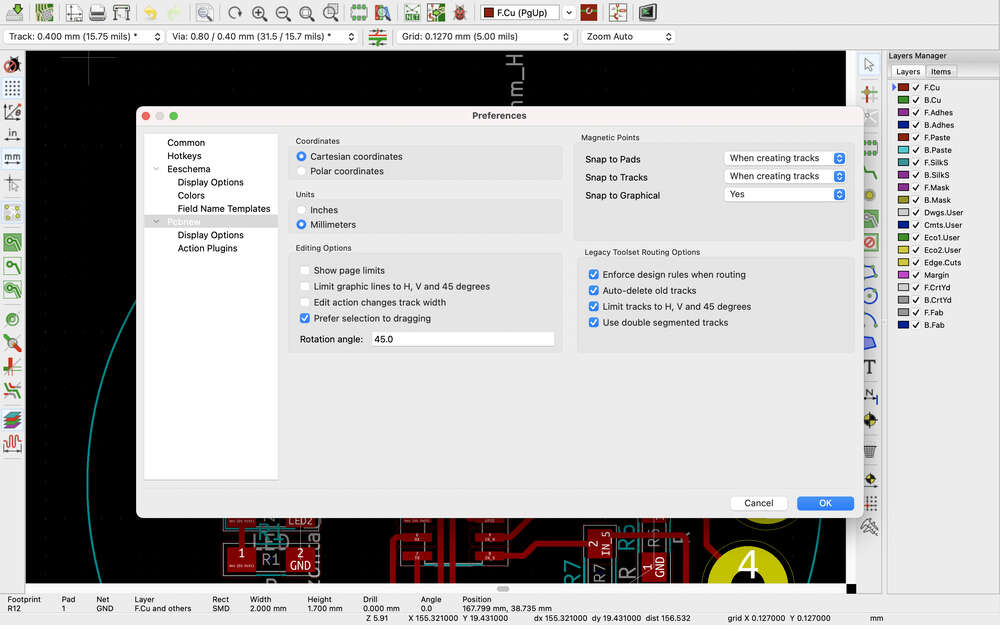
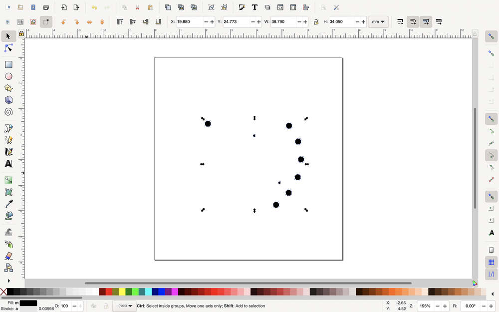
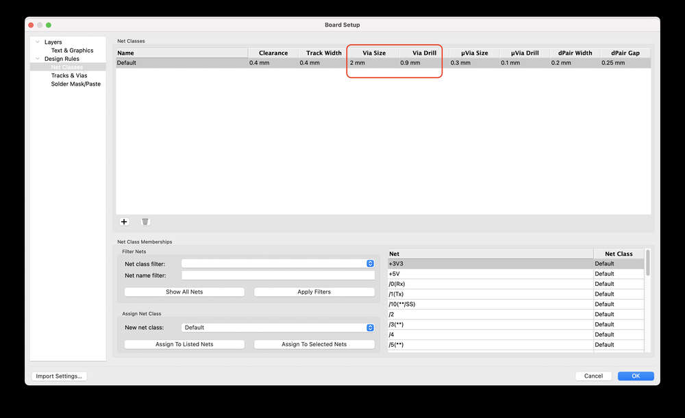
I set my via size to 2 mm and the drill hole to 0.9 mm.
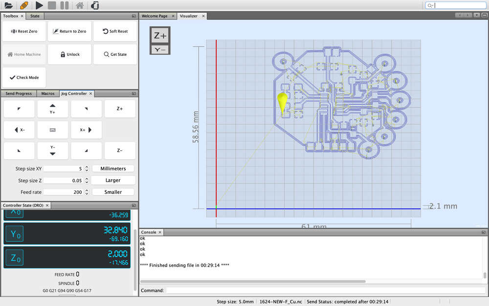
From KiCAD to Fabrication
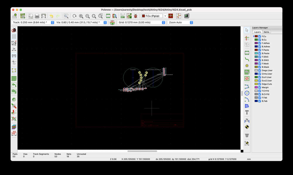
For some reason I am feeling a bit intimidated by the next step, trying to get from a the circuit diagram to the fabricated board. Perhaps because it has been awhile since I did it…perhaps because we have had some issues recently with the fabrication process, including some broken bits. In any case, I am going to try to get this board milling so that I can work on designing the other boards.
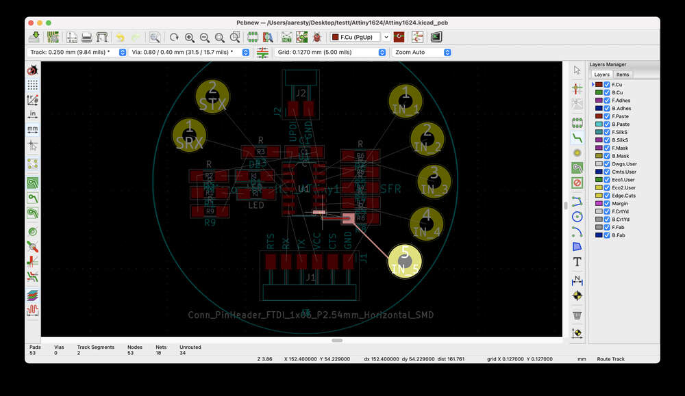
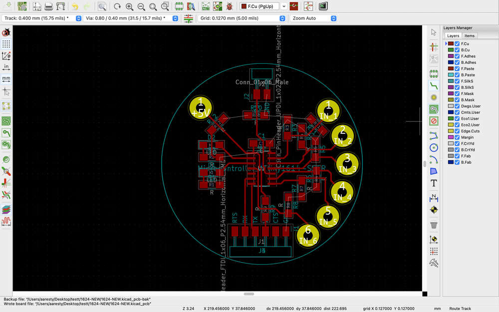
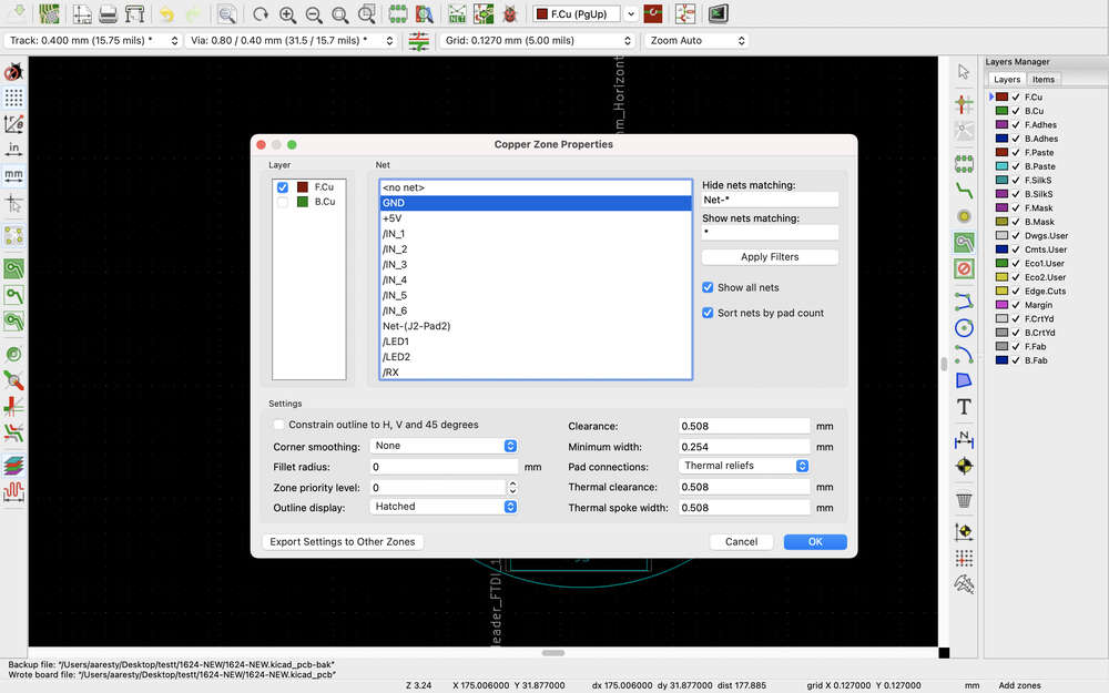
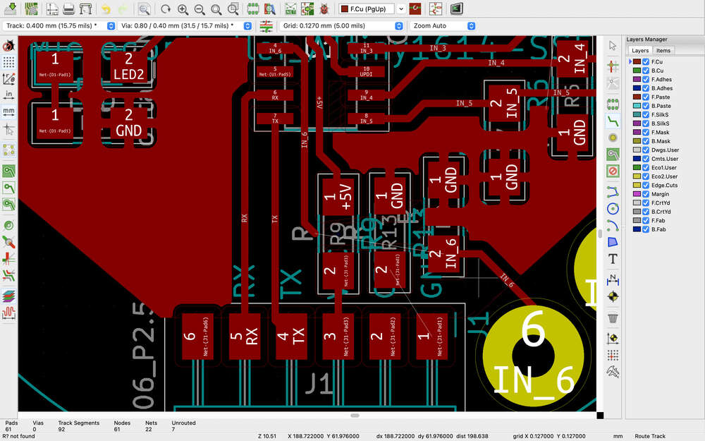
Because I decided to try to use vias this time around in my design, I was reviewing the Aalto Lab video about designing double sided PCBs, which you can find here. This reminded me about the design rules check and I was really glad I ran one because I found that I had several items that were not routed at all, as well as at least one location where there was not enough space between tracks. I routed the remaining tracks and rerouted the track where the bright red arrow had appeared and reran the design rules check. It seems that this worked!
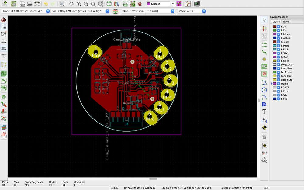
From this video, also, I was reminded that when preparing KiCAD files for working with mods, in addition to the edge cuts layer, you also need an identical user drawings layer – I don’t fully understand why – as well as a margin layer that helps create an offset in mods so that the circuit board file is not right at the zeroed location. I didn’t want to have
Now I understand the point of the drawings user layer…it is to create a filled polygon for use with mods. The edgecuts are not filled and you need a filled polygon to be able to generate the board outline.
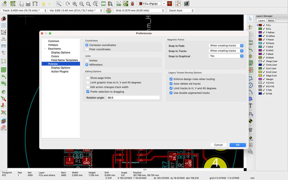
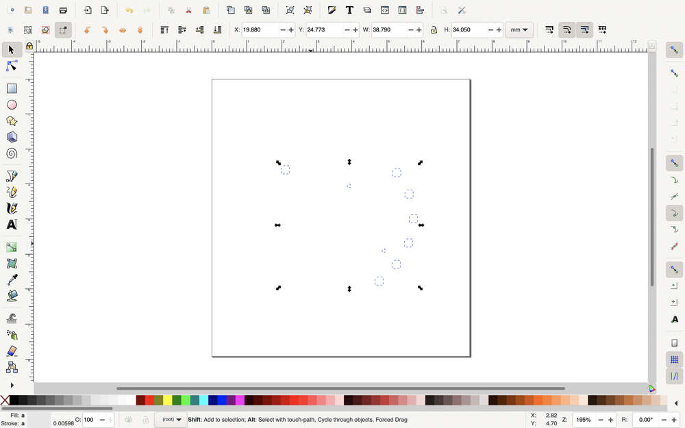
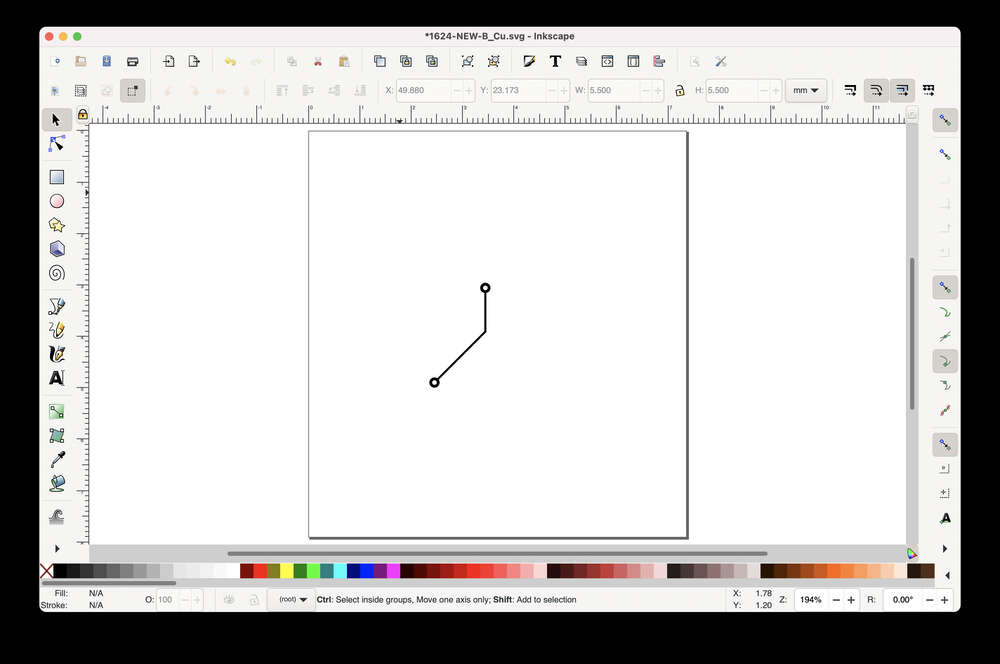
I got to the point of separating out the vias in inkscape only to realize that these were somehow set to 0.4 mm when they should have been set to 0.8. I’m going to have to recreate the gcode.
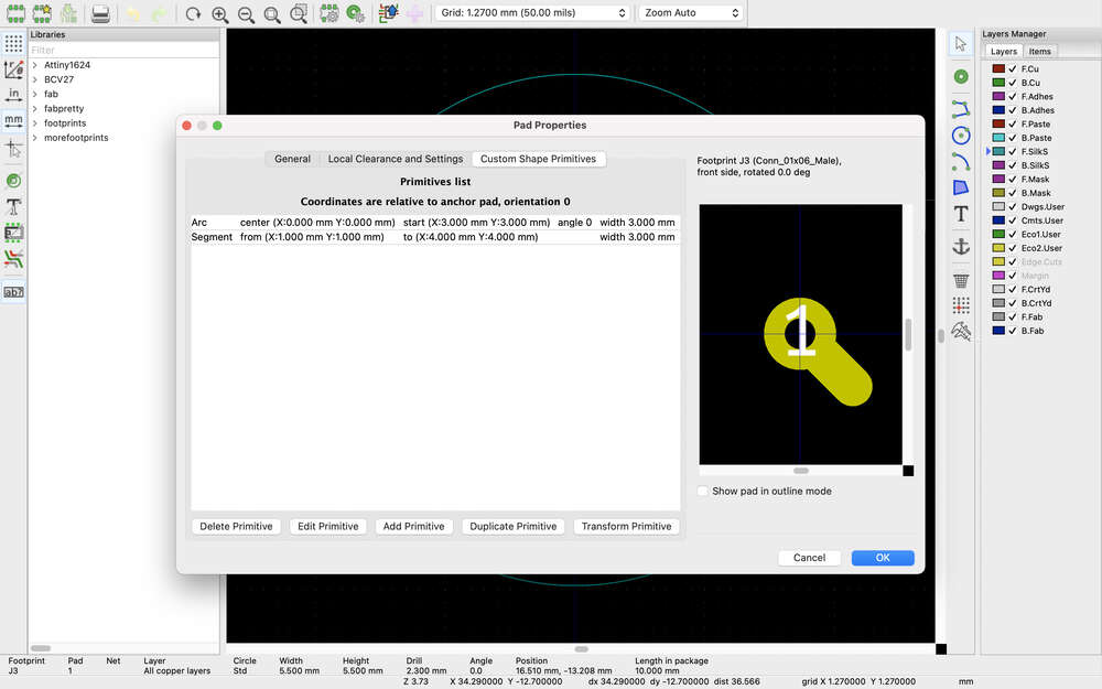
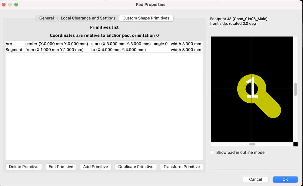
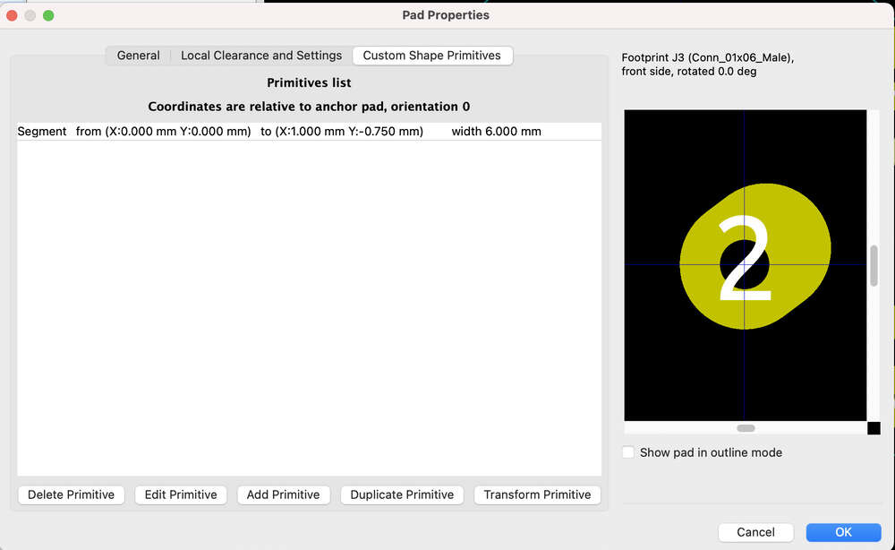
Time of Flight Sensor
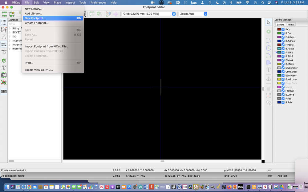
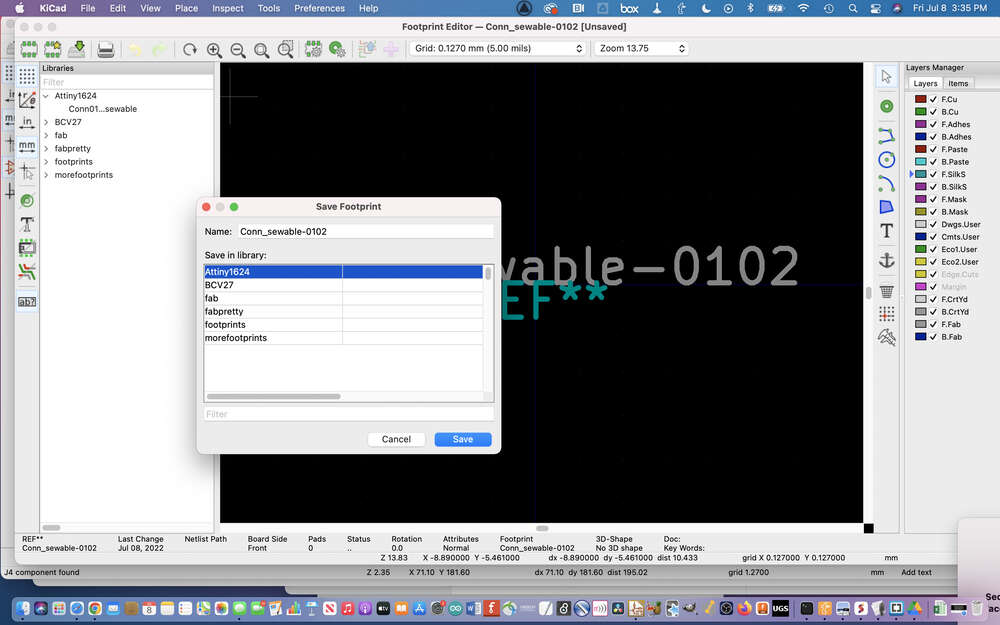
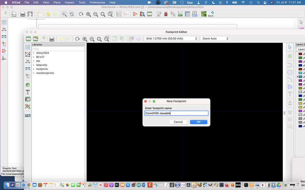
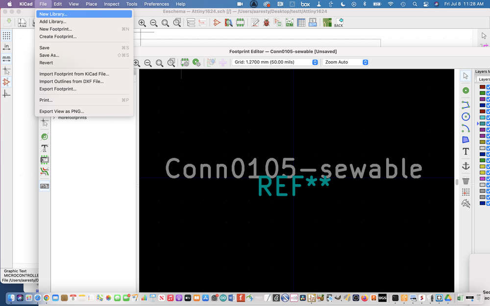
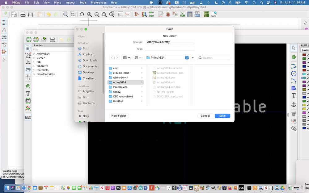
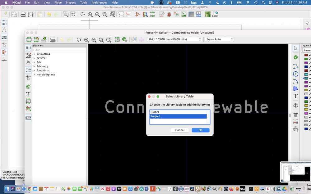
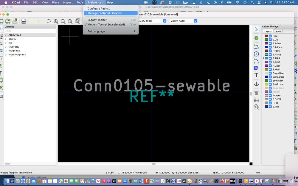
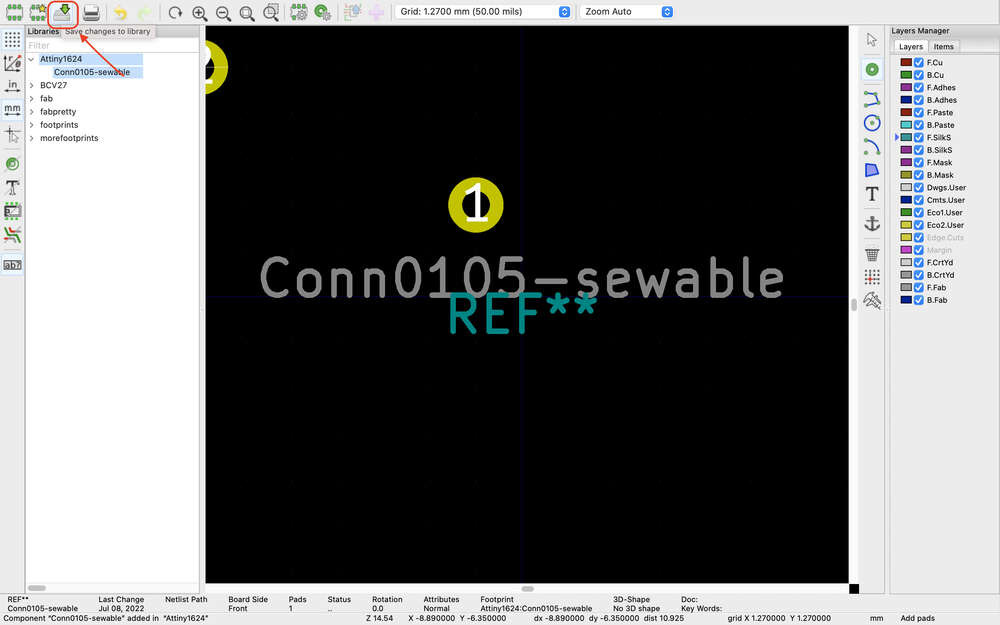
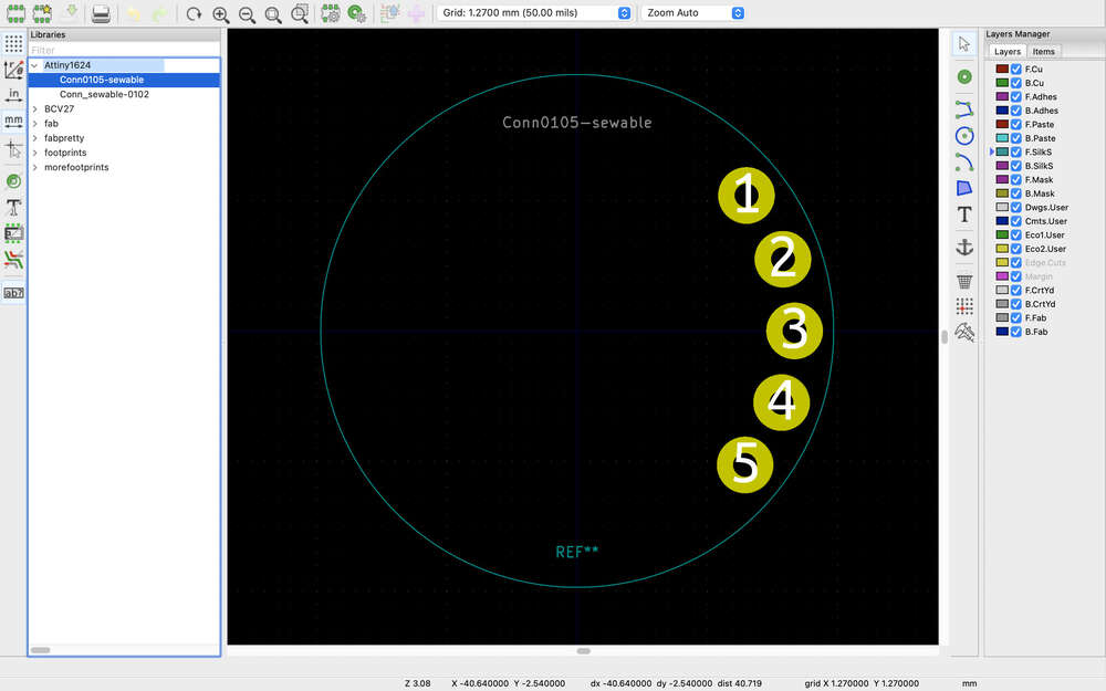
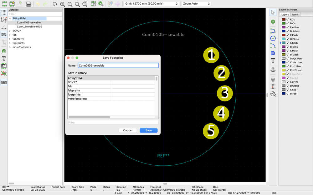
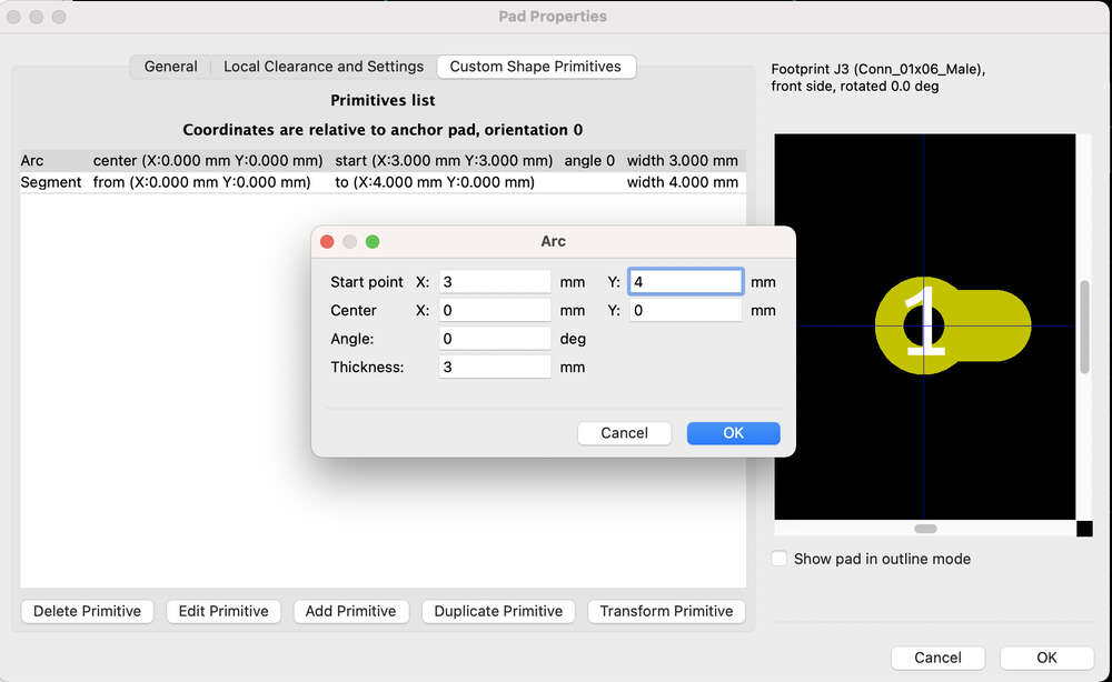
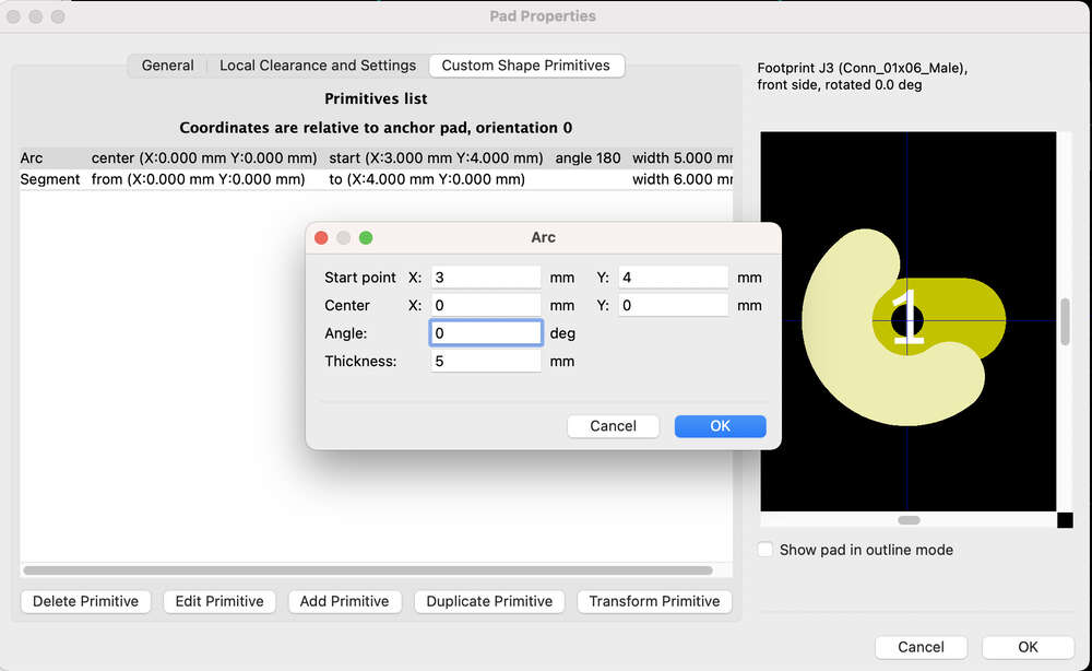
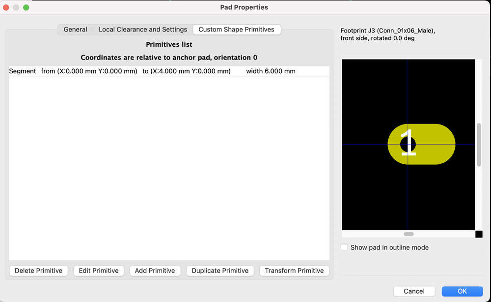
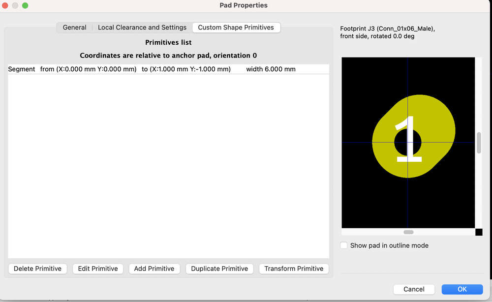
Symbol and Footprint Editors
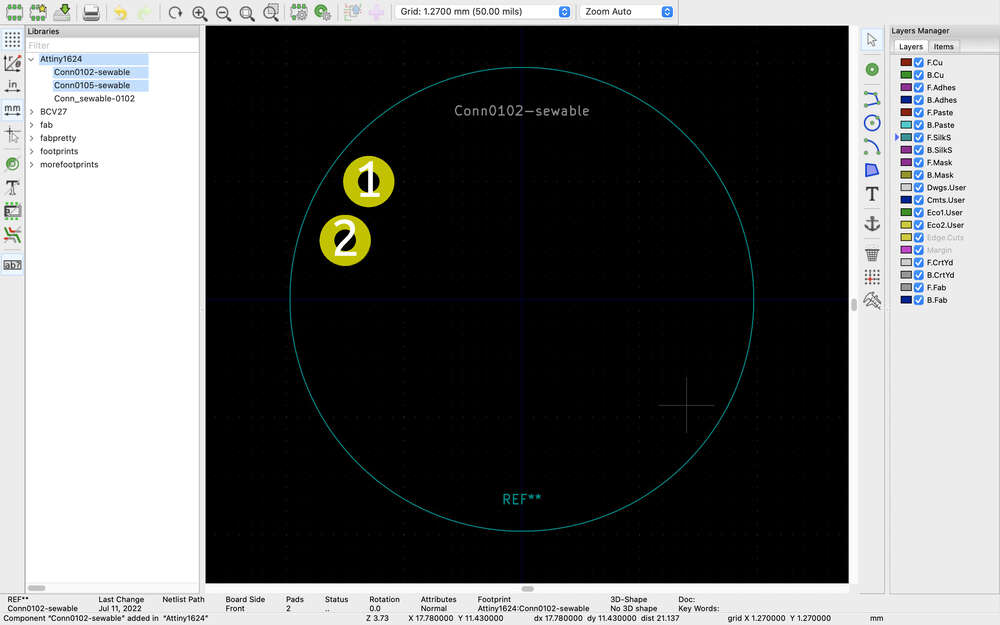
The second sensor I wanted to try out was a time of flight sensor. I am using a slightly different time of flight sensor and I realized that I needed to create my own symbol and footprint. I also couldn’t find the footprint for the tof module, which I was originally planning simply to edit.
https://www.youtube.com/watch?v=c2niS9ZRBHo
“Lorem ipsum dolor sit amet, consectetur adipiscing elit, sed do eiusmod tempor incididunt ut labore et dolore magna aliqua. Ut enim ad minim veniam, quis nostrud exercitation ullamco laboris nisi ut aliquip ex ea commodo consequat. Duis aute irure dolor in reprehenderit in voluptate velit esse cillum dolore eu fugiat nulla pariatur. Excepteur sint occaecat cupidatat non proident, sunt in culpa qui officia deserunt mollit anim id est laborum.”
“Lorem ipsum dolor sit amet, consectetur adipiscing elit, sed do eiusmod tempor incididunt ut labore et dolore magna aliqua. Ut enim ad minim veniam, quis nostrud exercitation ullamco laboris nisi ut aliquip ex ea commodo consequat. Duis aute irure dolor in reprehenderit in voluptate velit esse cillum dolore eu fugiat nulla pariatur. Excepteur sint occaecat cupidatat non proident, sunt in culpa qui officia deserunt mollit anim id est laborum.”
Useful links
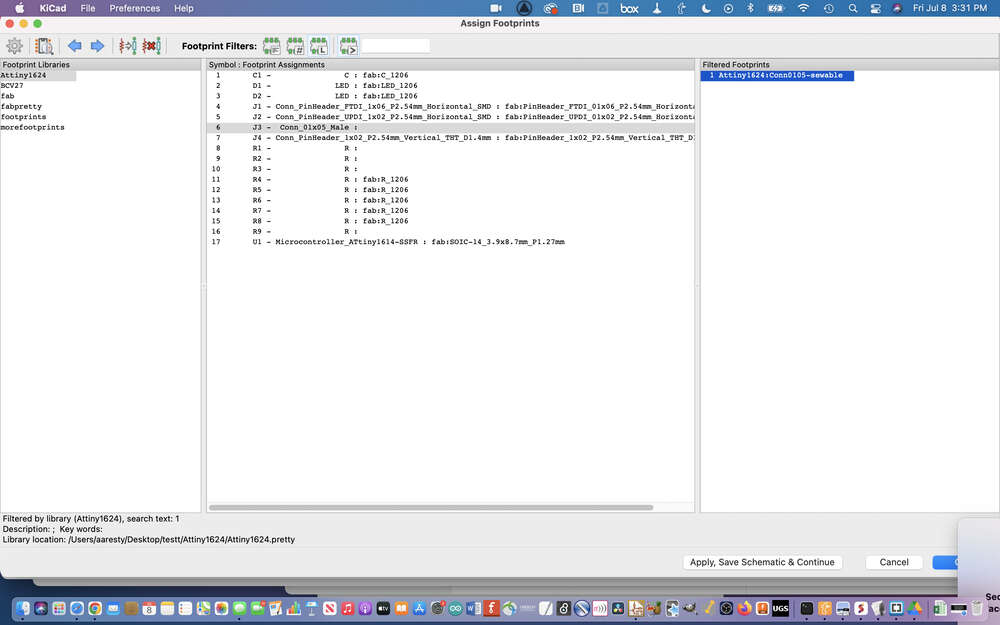
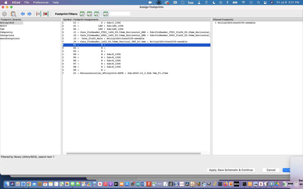
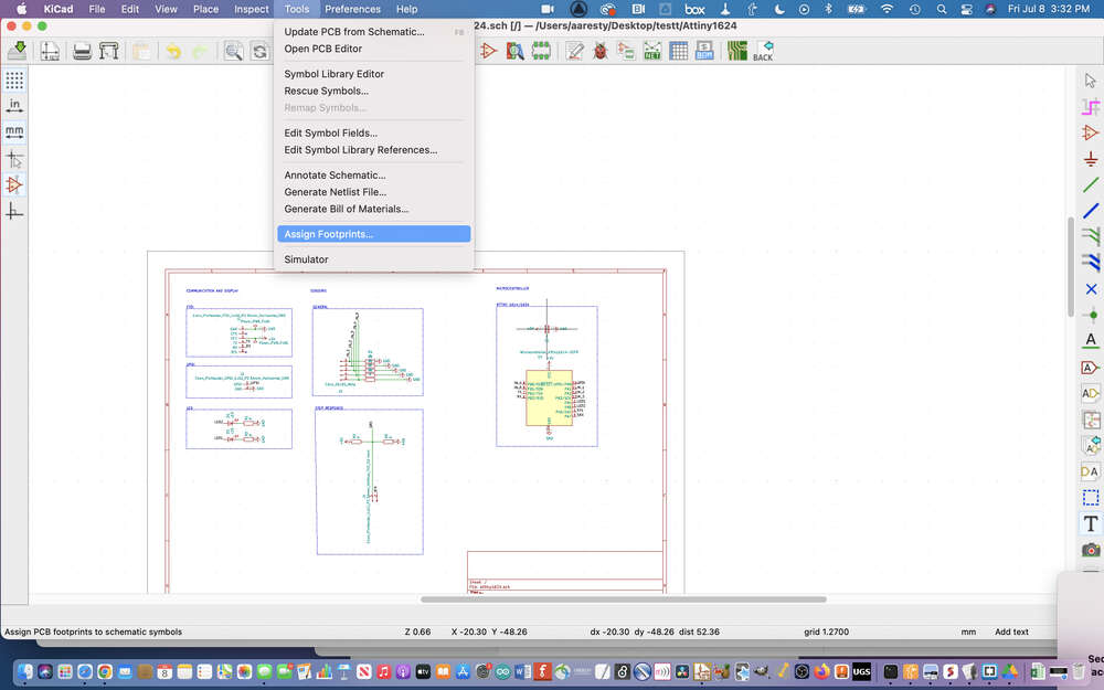
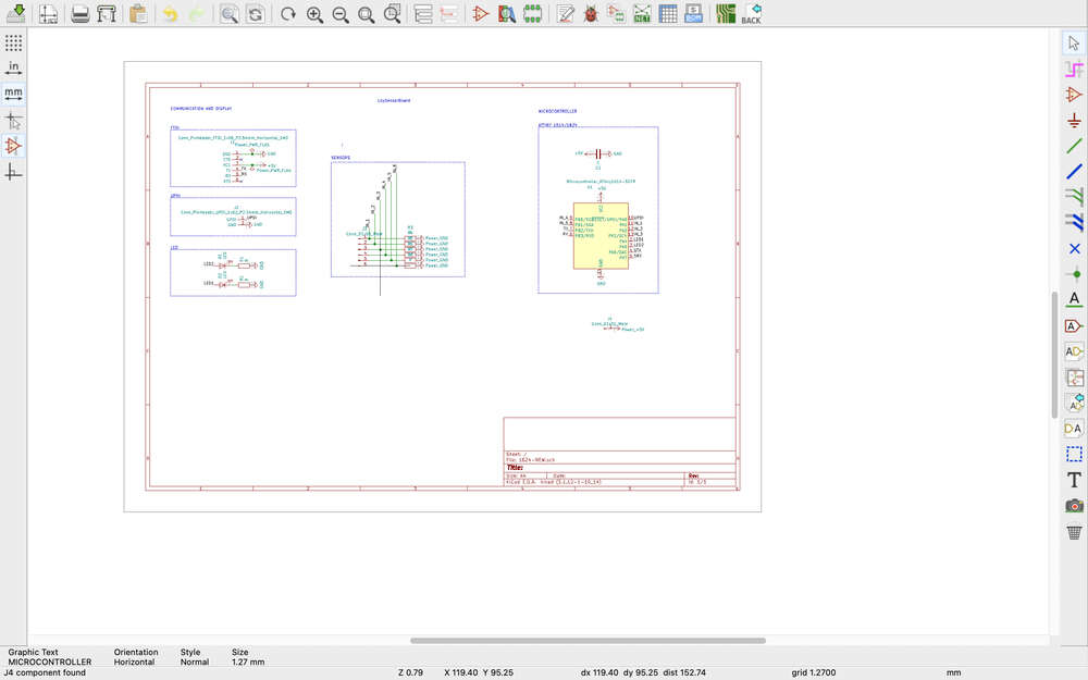
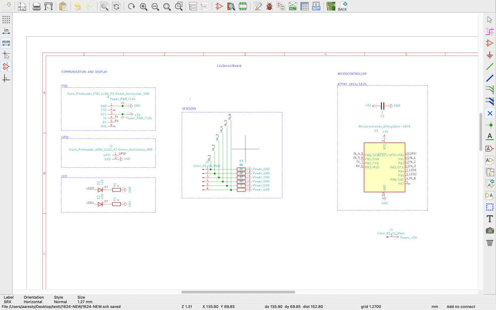
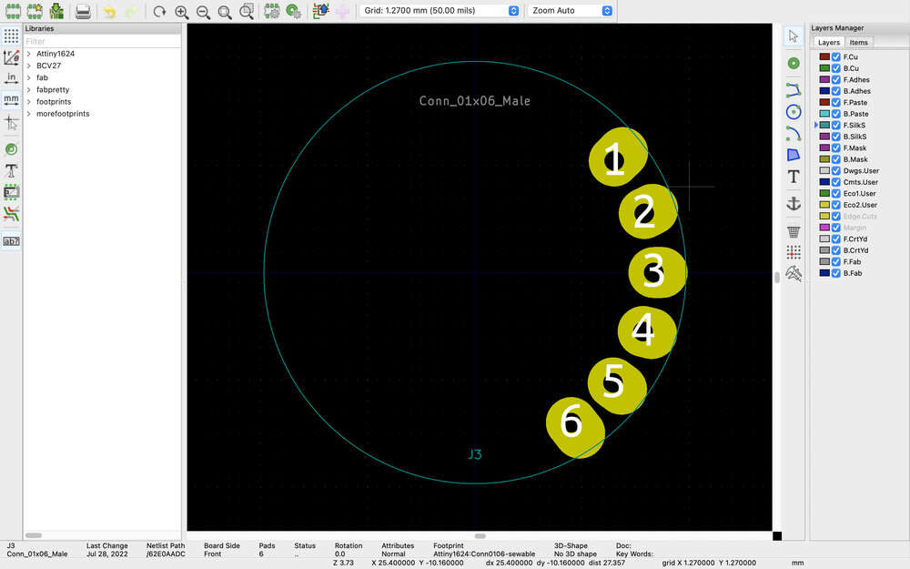
July - LilyPad Version
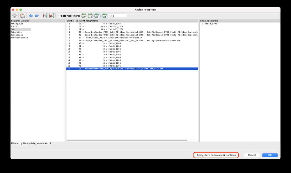
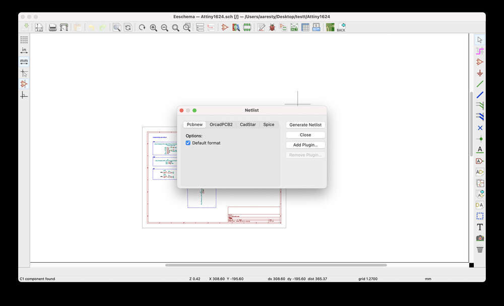
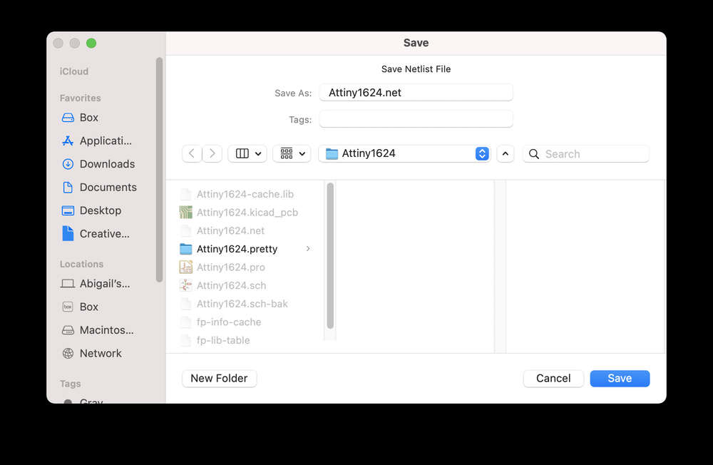
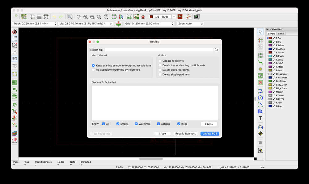
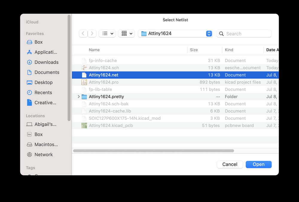
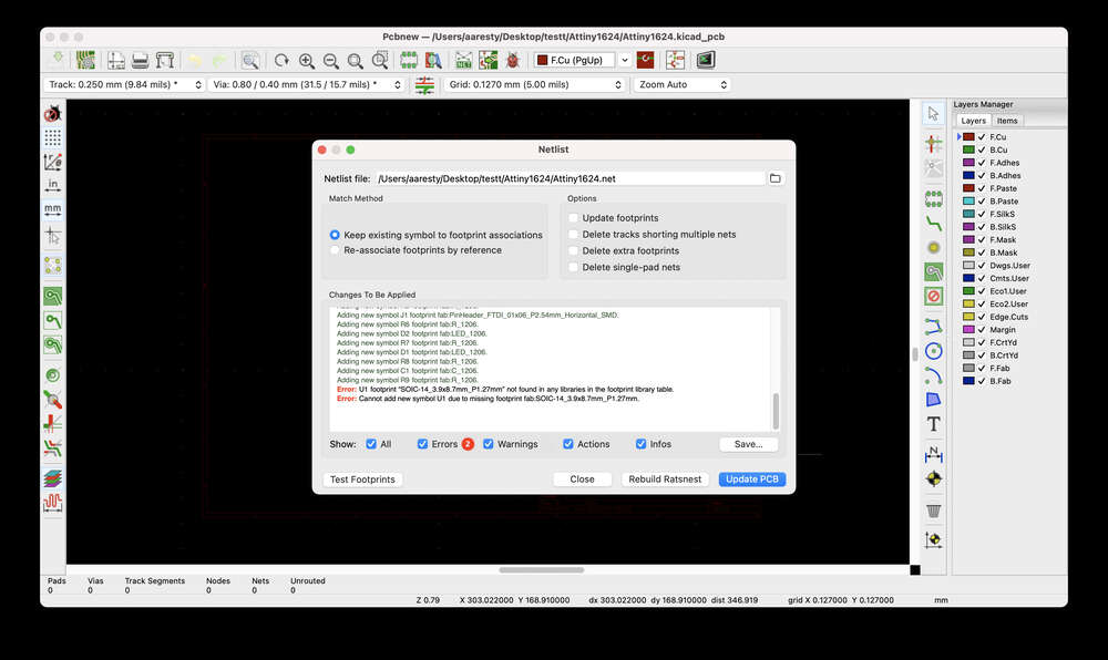
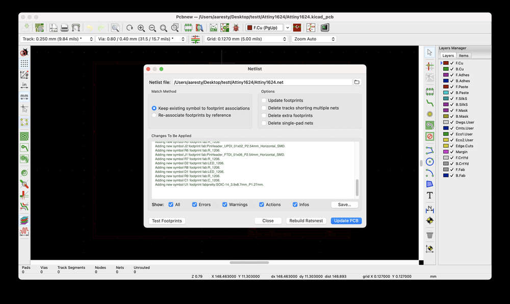
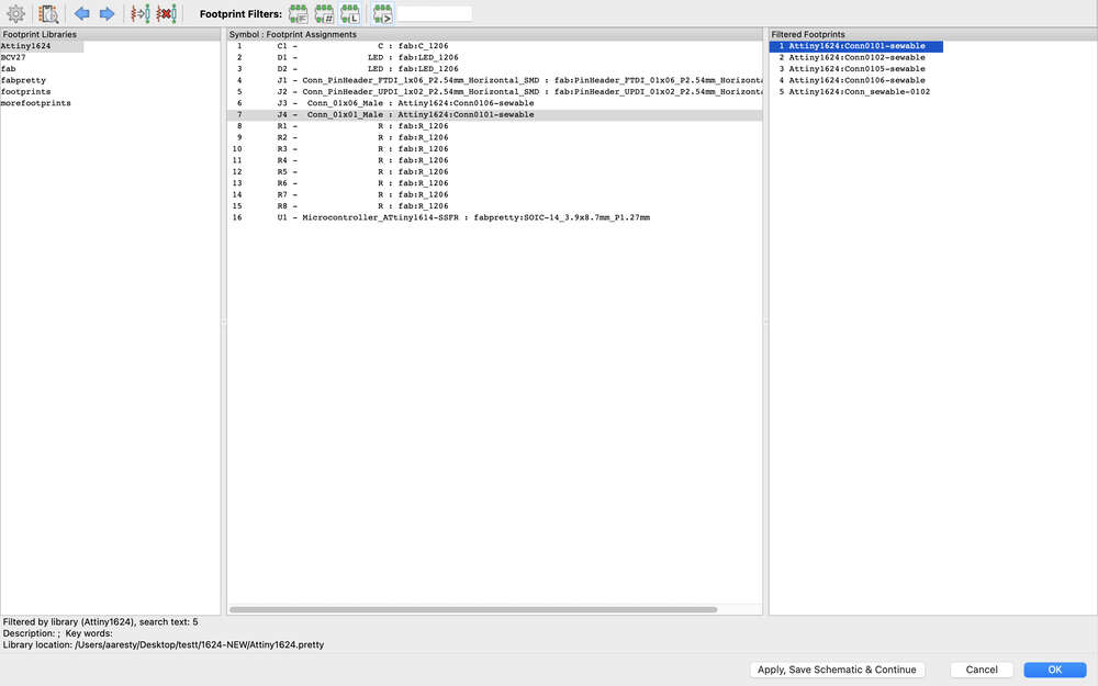
I assigned alternative custom-made footprints inspired by the LilyPad’s design. Strangely, when I generated a netlist, one of the footprints that was automatically assigend threw an error. I fixed this simply by reassigning the same footprint to the component and it seems to have worked.
Resources and tutorials to explore further
Pressure sensor https://learn.adafruit.com/force-sensitive-resistor-fsr
Arduino https://create.arduino.cc/projecthub/thelastjedi/pressure-pad-interfacing-with-arduino-efacad https://www.tinkercad.com/things/5kyr6NSO3Vb
E-textiles (basic and variations) https://docs.google.com/document/d/1ZJbO_knVd3o2jhZOySvav3dXYIFKJ9RmMDoa4lhXTCk/edit?usp=sharing https://www.kobakant.at/DIY/?p=65 https://www.kobakant.at/DIY/?p=3175 https://www.kobakant.at/DIY/?p=5210 https://www.kobakant.at/DIY/?p=6005
Tilt sensor on/off What is a tilt sensor? https://learn.adafruit.com/tilt-sensor
https://littlebirdelectronics.com.au/guides/102/use-a-tilt-sensor-with-arduino https://docs.arduino.cc/tutorials/generic/tilt-sensor https://arduinointro.com/projects/tilt-sensor-with-arduino-easy-tutorial https://www.instructables.com/Arduino-Tilt-Sensor-Tutorial-Interfacing-Tilt-Ball/ https://learn.adafruit.com/tilt-sensor/using-a-tilt-sensor
https://www.kobakant.at/DIY/?p=6218 https://www.kobakant.at/DIY/?p=201 https://www.kobakant.at/DIY/?p=2409 https://www.kobakant.at/DIY/?p=5390
Brings up an issue with my current design: -these all go to digital pins and at least one has a pull-up resistor whereas my design goes to all analog pins and has a pulldown design.
It technically should still be able to work if I use the existing design but it would be a slightly wonky way of connecting it
I wonder whether I would need to make the circuit itself flexible and interchangeable, so that you could snap in or out the microcontroller itself as necessary?
Tilt sensor pot https://www.kobakant.at/DIY/?p=6231 https://www.kobakant.at/DIY/?p=7706 Synth pot https://www.instructables.com/The-Arduino-Synthesizer/
Resistor ladder https://www.tinkercad.com/things/3YxWBrx1aK5 No sound? https://www.tinkercad.com/things/0ggqL2MHNdt https://www.hackster.io/chariscat/building-the-auduino-synthesiser-arduino-based-diy-synth-fcd832
https://www.electronics-tutorials.ws/resistor/potentiometer.html
https://makezine.com/projects/arduino-photocell-theremin/ https://docs.arduino.cc/built-in-examples/basics/AnalogReadSerial https://roboticsbackend.com/arduino-potentiometer-complete-tutorial/ https://www.instructables.com/How-to-use-Potentiometer-Arduino-Tutorial/
Matrix Microphone Capacitive / distance sensor Stretch sensor
Code Example
Use the three backticks to separate code.
// the setup function runs once when you press reset or power the board
void setup() {
  // initialize digital pin LED_BUILTIN as an output.
  pinMode(LED_BUILTIN, OUTPUT);
}

// the loop function runs over and over again forever
void loop() {
  digitalWrite(LED_BUILTIN, HIGH);   // turn the LED on (HIGH is the voltage level)
  delay(1000);                       // wait for a second
  digitalWrite(LED_BUILTIN, LOW);    // turn the LED off by making the voltage LOW
  delay(1000);                       // wait for a second
}
Gallery


Video
From Vimeo
Sound Waves from George Gally (Radarboy) on Vimeo.