5. Electronics Production
Or: how I learned to trust the process(or).
Pre-work
-
Microcontrollers explained by Akshara Ganesh Ram, thank you!
-
SparkFun Tutorial on PCBs and Electronics; very helpful place to start.
-
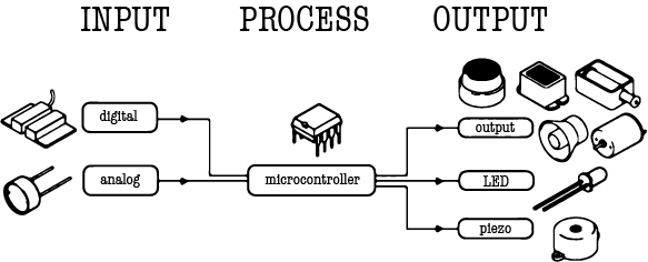
Start with things that exist! It’s a bit wild to write a book (…and print it and bind it) before learning how to read. I spent time revisiting MakeCode Micro:bit here and getting reacquainted with inputs outputs and basic components. The online simulator component is awesome. And blinking an LED with Arduino never hurts.
-
Fritzing is a tool that allows you to map out your boards (like connecting an Arduino to a bread board and laying out all the connecting wires). This is a great teaching tool!
-
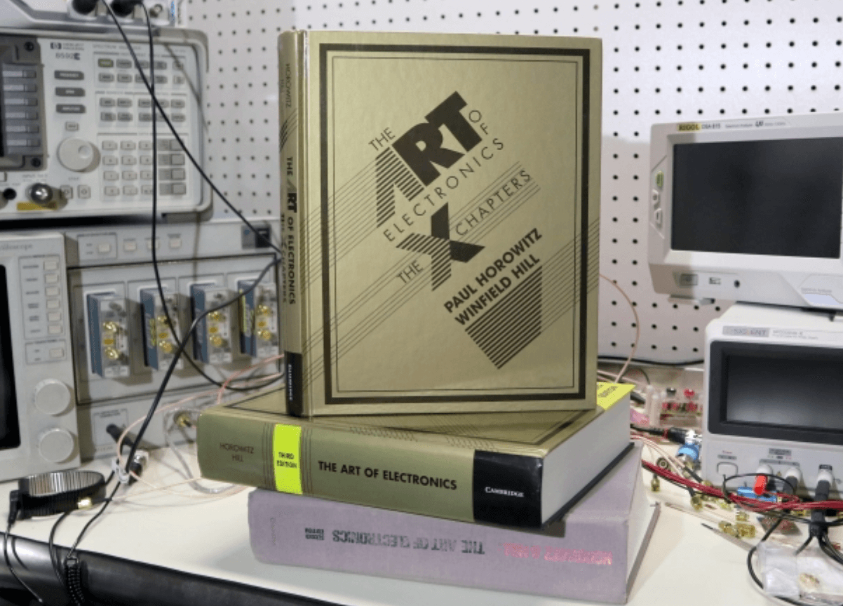
And if you visit your dad over the weekend who’s a physics professor at NYU and share vague confusion about electronics, you’ll go home with thirty pounds of Horowitz books.
Words and Things:
- Resistors: Control Energy
- Capacitors: Store Energy
- Transformers: Transfer Energy
- Transistors: Amplify Energy
- Diodes: Redirect Energy
- Battery: Provides Energy
- Integrated Circuits: Multi-Function Powerhouses
- Oscillators: Precise Timers
- Inductors: Increase Energy
- Switches: Power Buttons
- Potentiometers: Varied Resistance
- Sensors: Sense Physical Input and React Accordingly
- FabTinyISP: In-System Programmer aka Low-Speed USB. This board is an archaic butterfly, starting out as an ISP and becoming an AVR (Alf and Vegard RISC -reduced instruction set computing- processor programmer).So you need a working AVR programmer to program it, but if everything goes well, the ISP board becomes a programmer that can program a new FabTinyISP. My confusion is vast.
Milling a Board
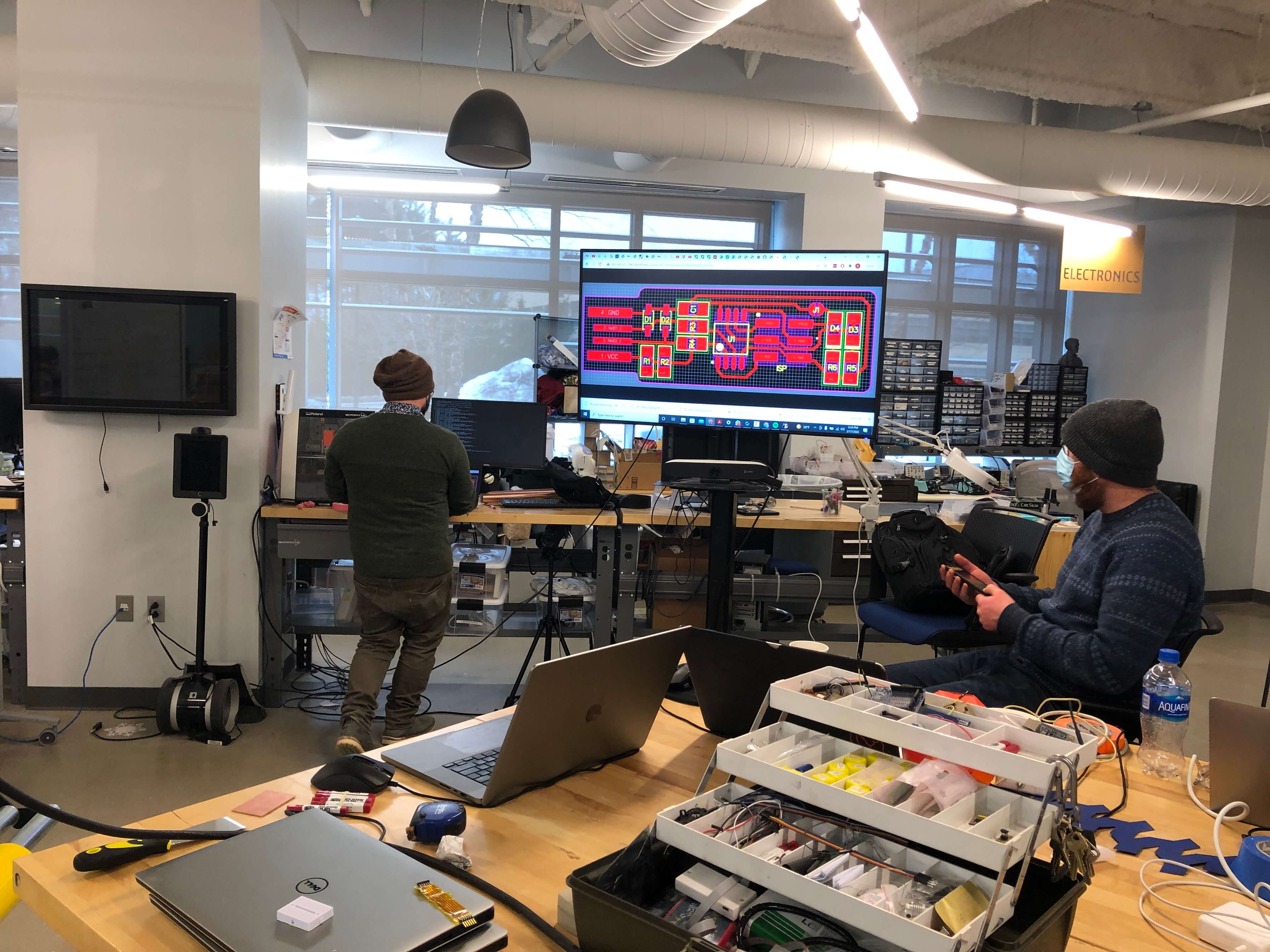
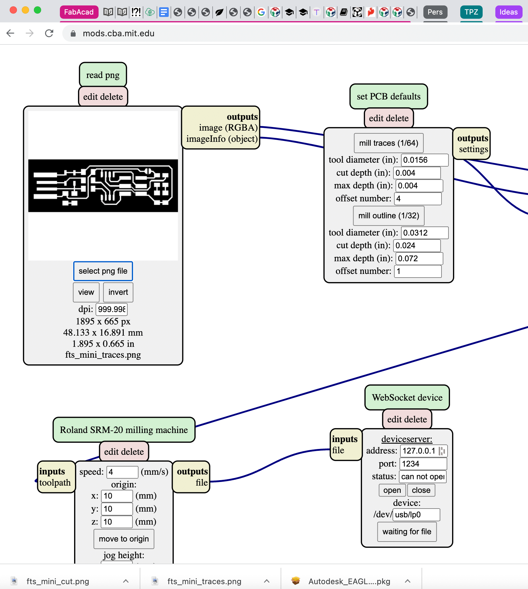 Using MODs as the CAM to run the traces and cut file for the circuit board.
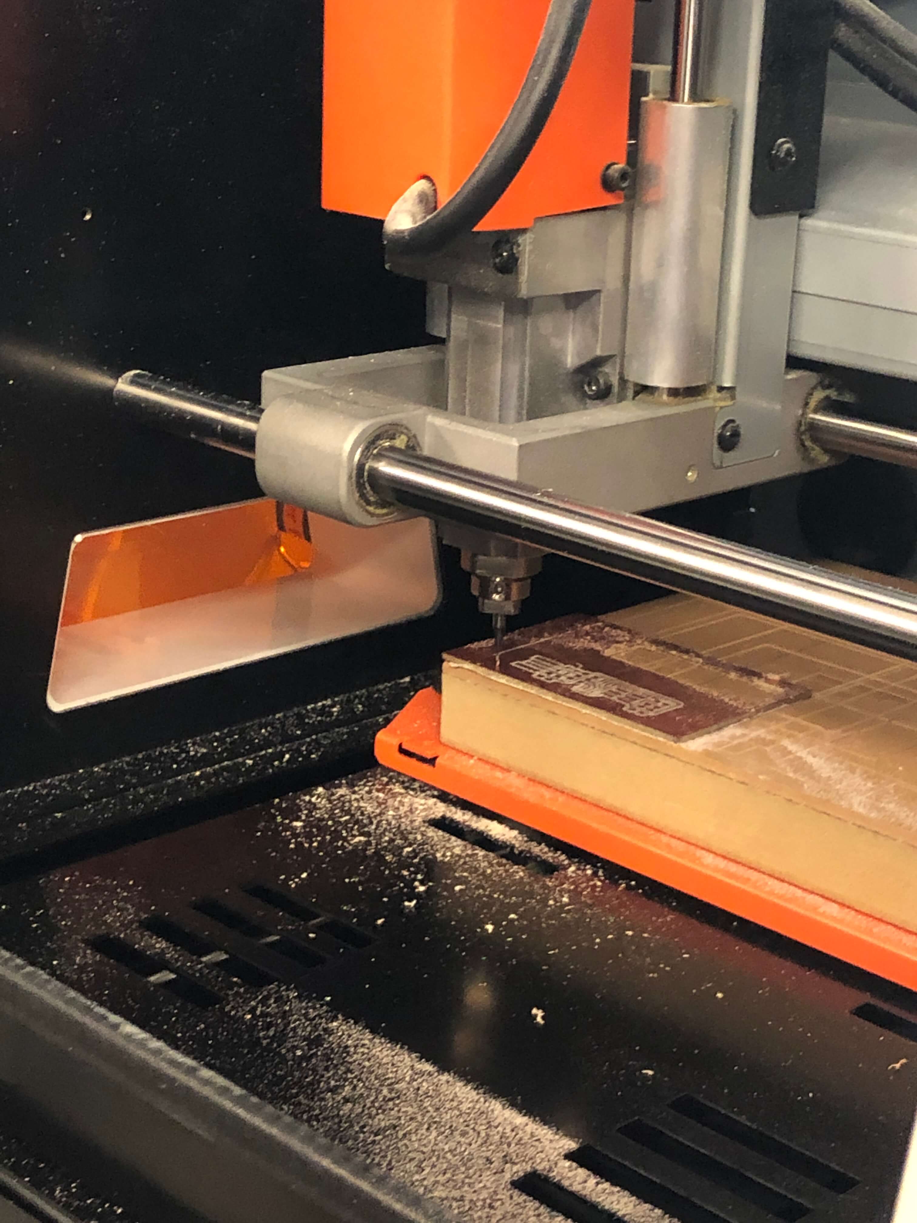 Using the Roland Milling machine at Dessault to run the traces and cuts (PNGs) from Brian’s tutorial using 1/64” end mill bit for traces; 1/32” for cutting.
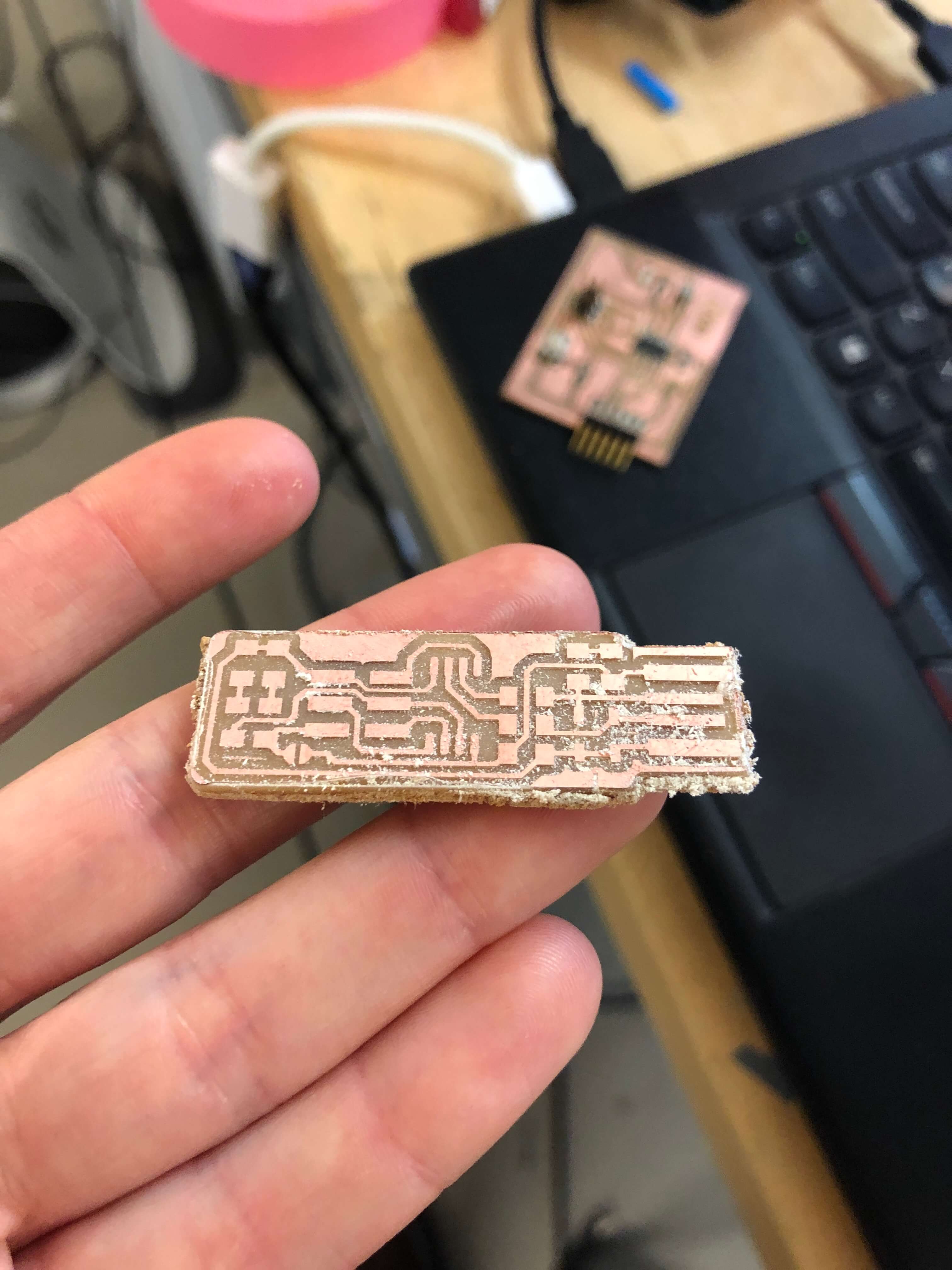 Hot off the press; traces and cuts for the FabTinyISP. (I’m not sure what that means yet).
 Spencer explains it all…
Soldering a Board
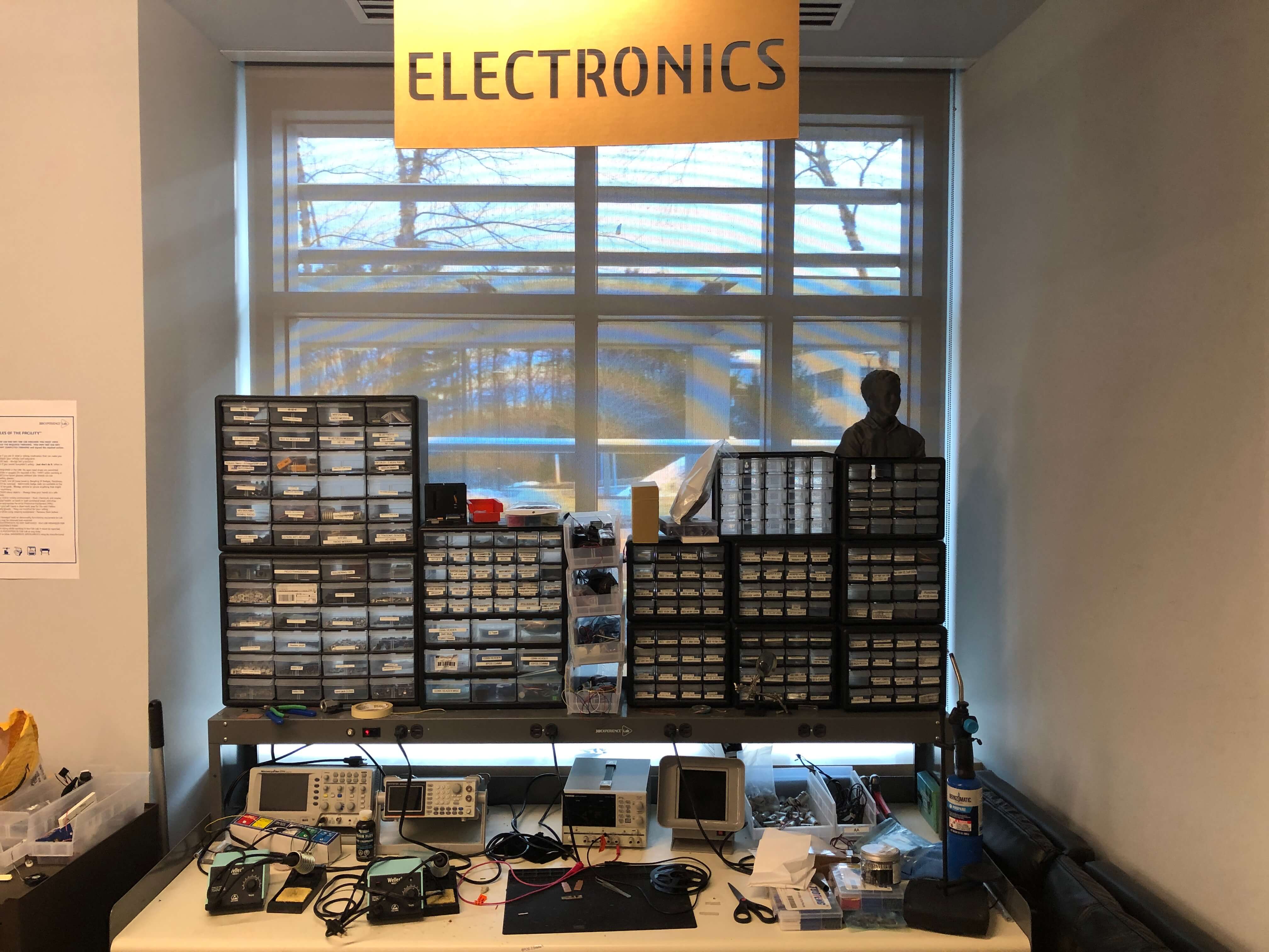 Acro-bins for days. With components that are indistinguishable from one another, good documentation starts in investing in a label maker.
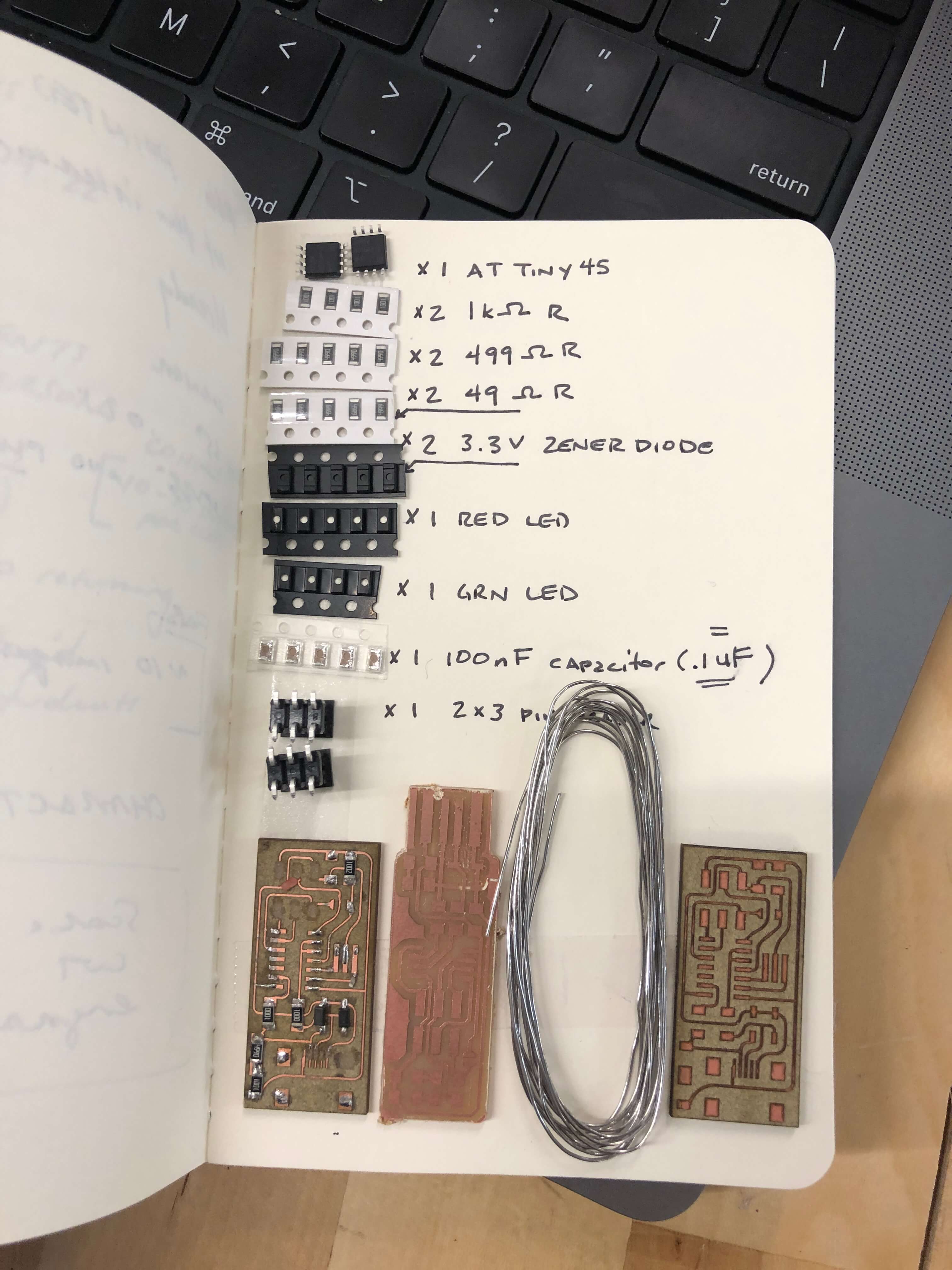 Shout out to double sided tape! This is a very helpful pro-tip for staging parts before soldering a board. Everything looks the same and you will need to get your eyes checked by the time you’re done with this assignment.
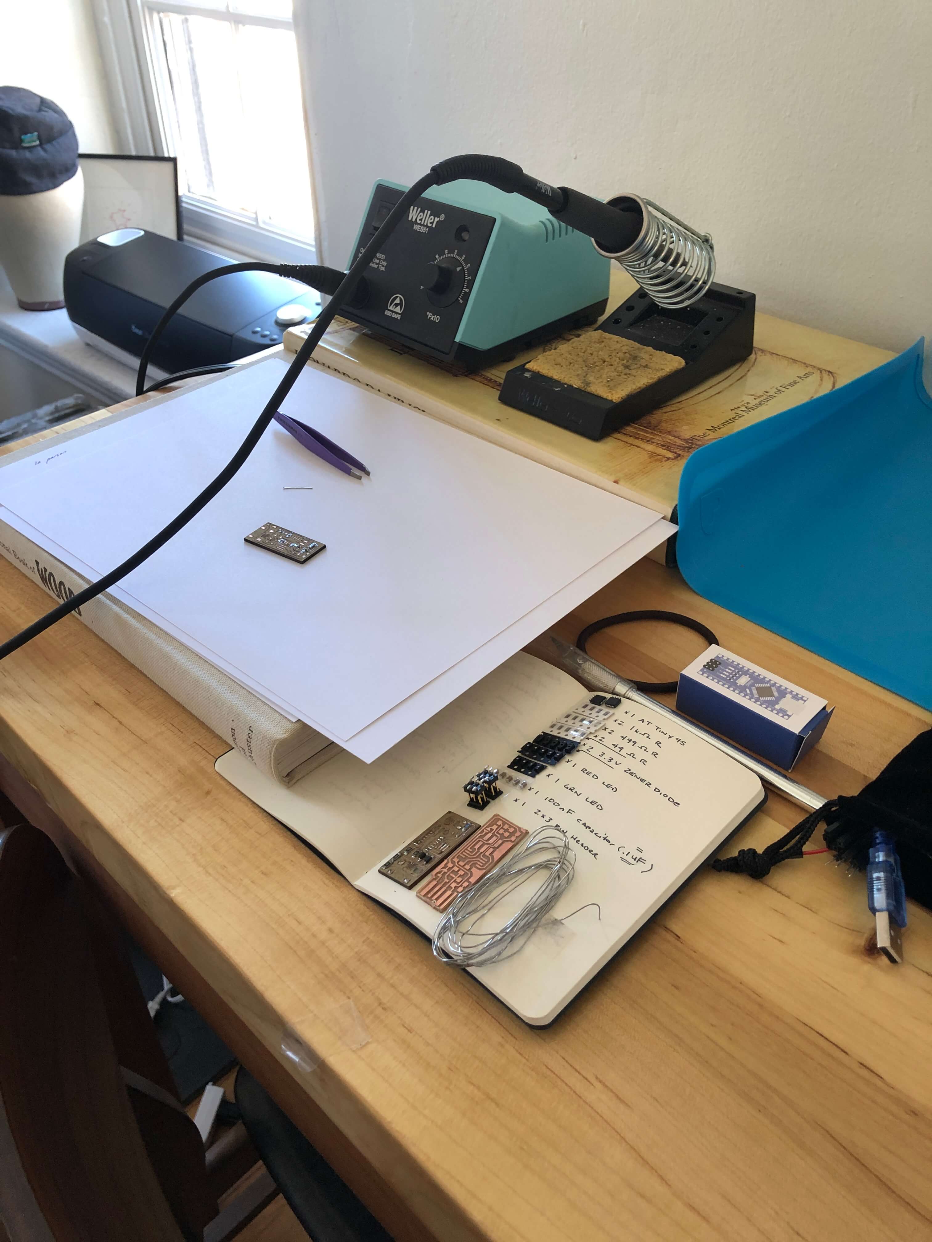 Setting up a soldering station to make tiny things at home. Still not sure what this is going to do… really leaning into trusting the process right now.
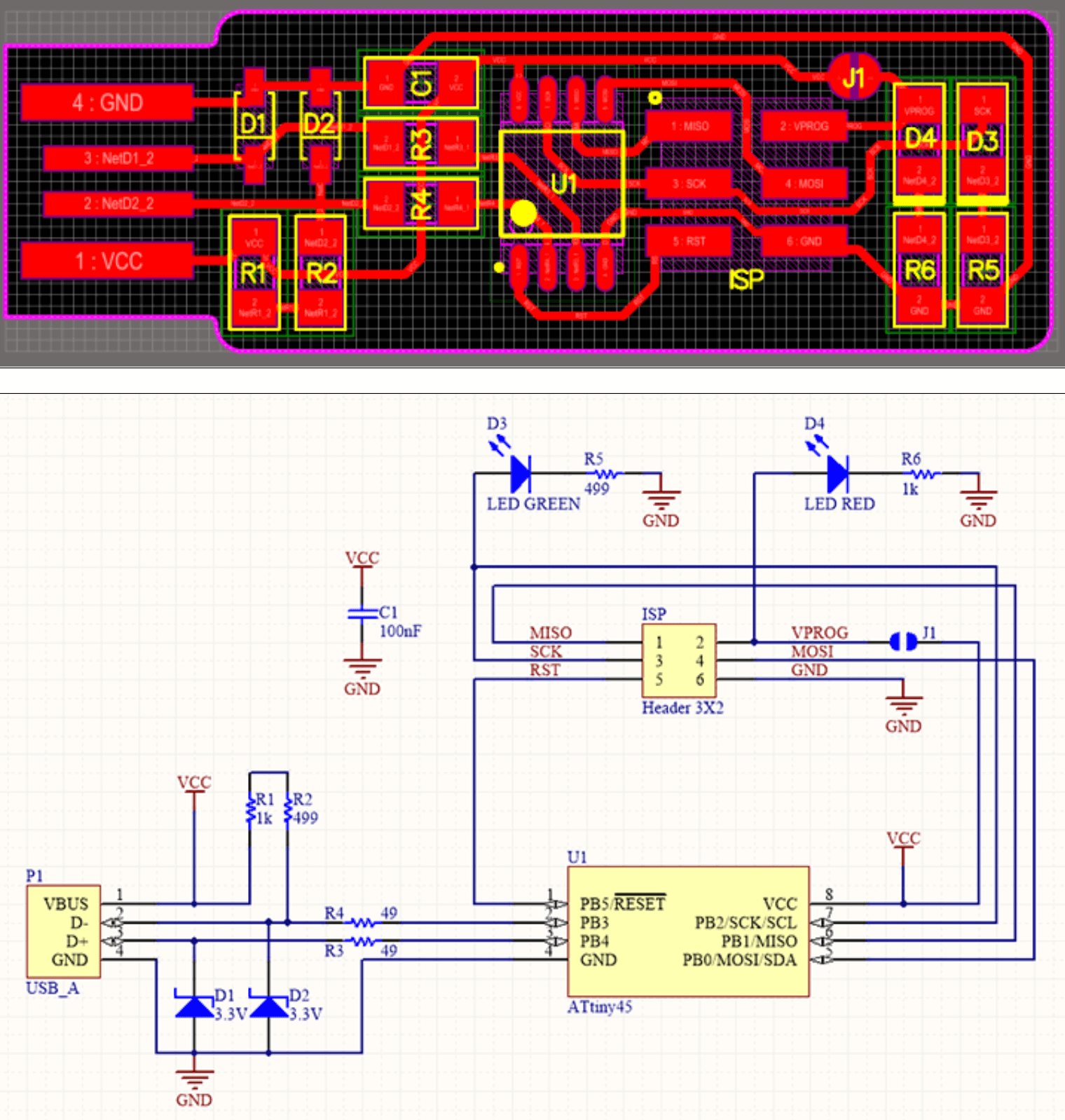 Follow the Board Image and Schematic carefully. Orientation matters for many components (zener diode was hardest to read) and they like to jump around.
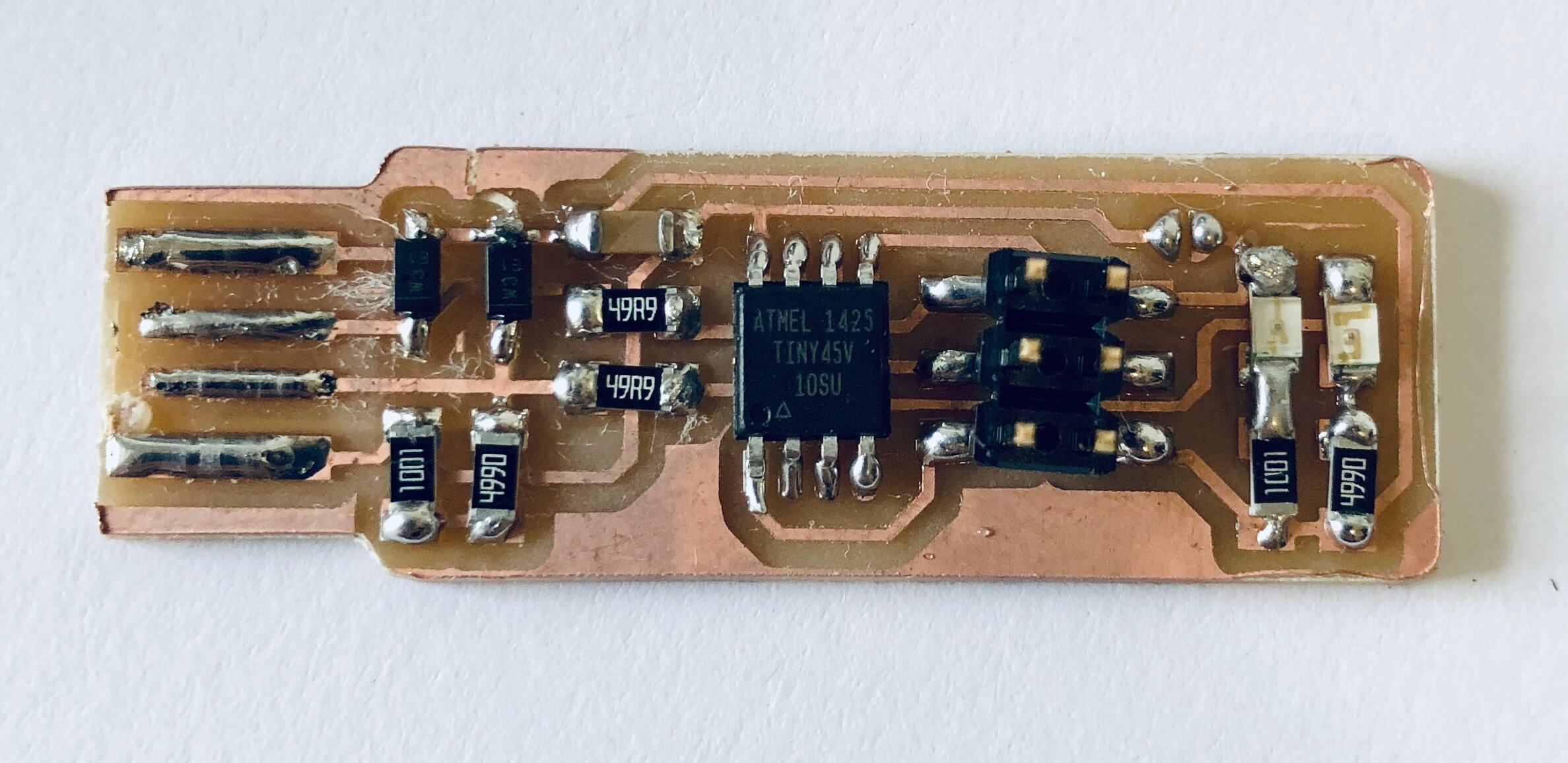 Hey! A built board! But what will it do?!
Programming a Board
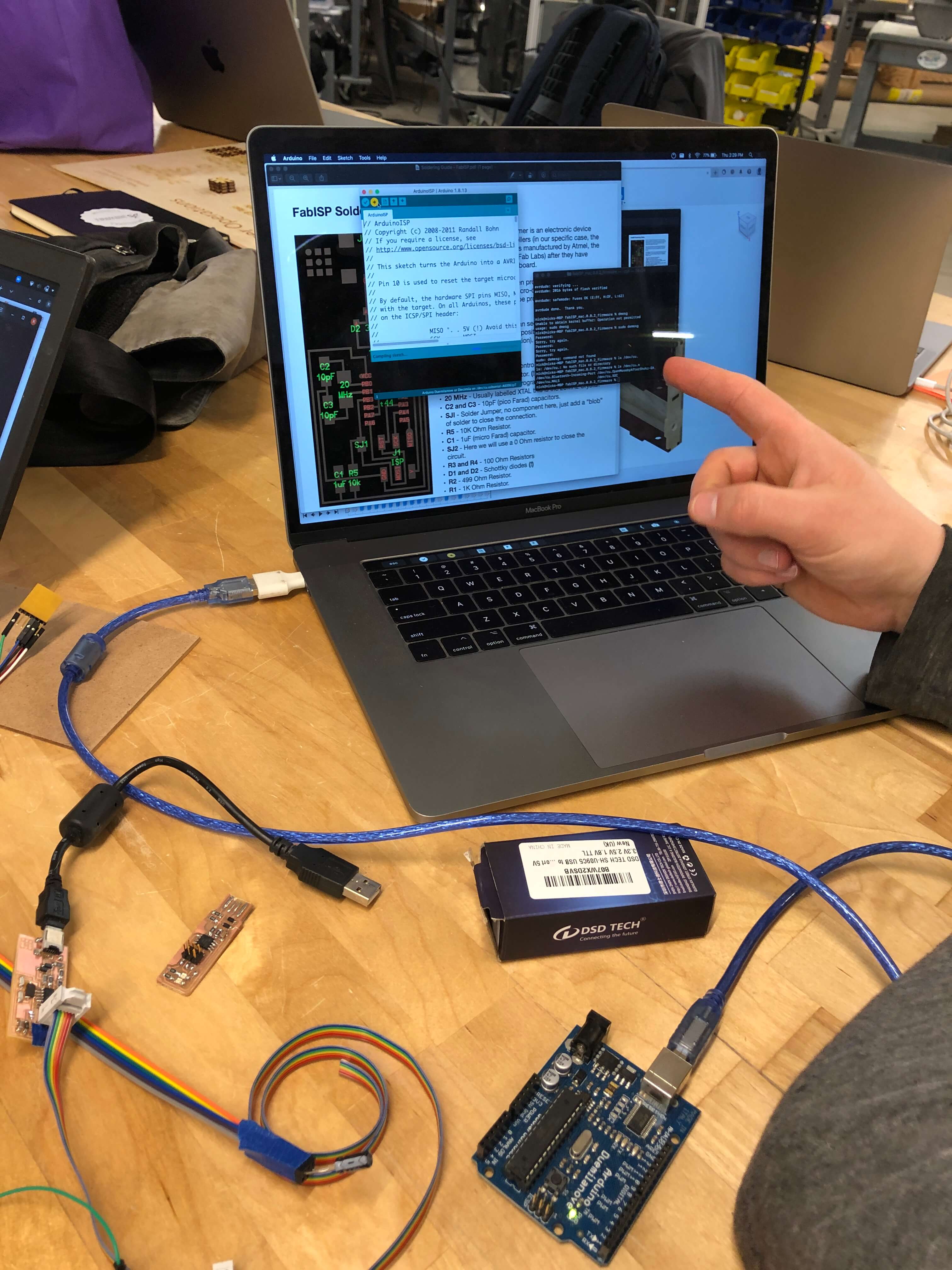
 We plugged in the FabTinyISP and the red LED came on!
 We then yelled at the computer because it seemed to not recognize the FabTinyISP
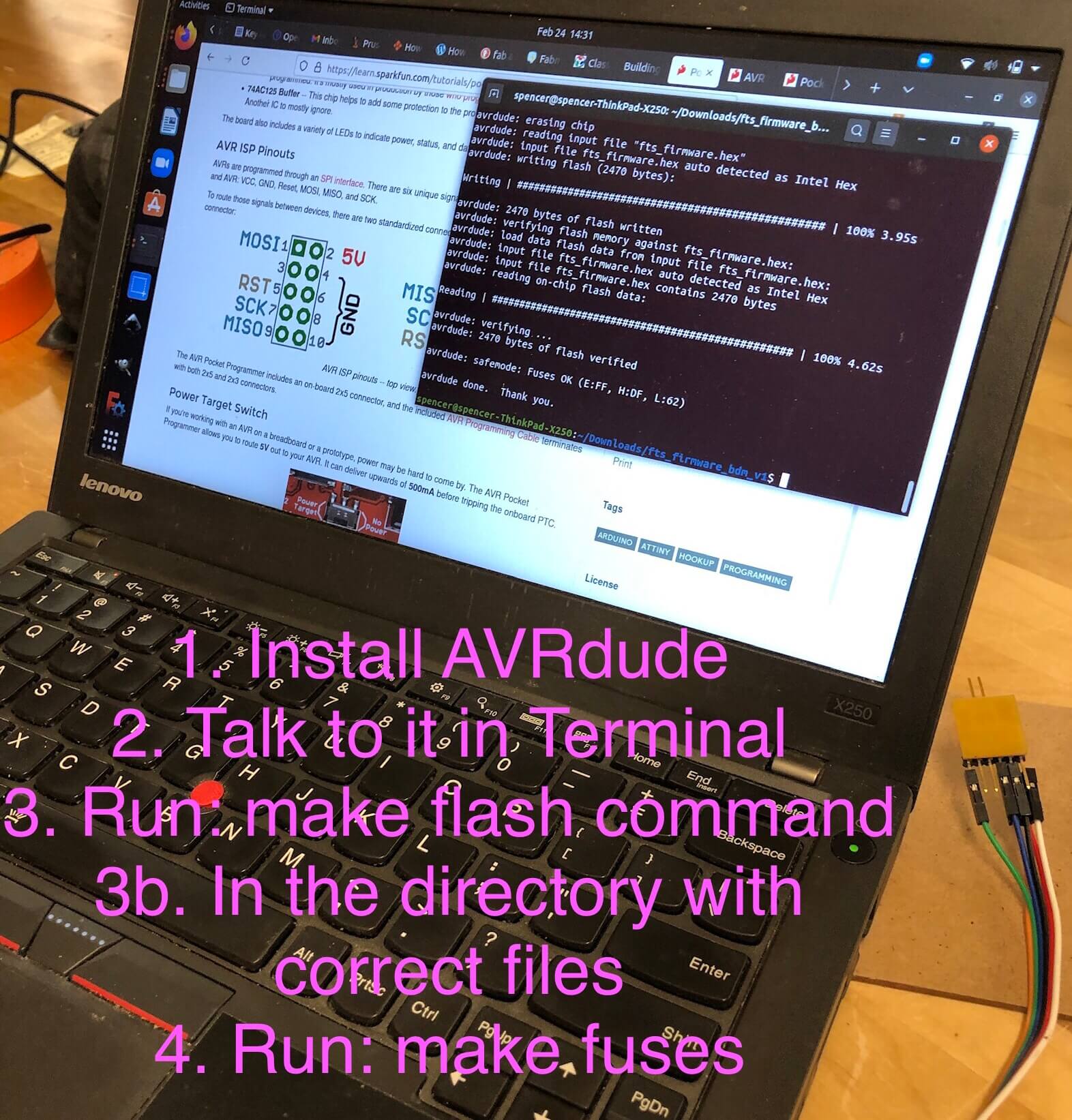 We installed AVRdude and talked to the board using Terminal; then we ran make flash command using the proper directory with the correct files from Brian’s tutorial. Then we ran make fuses command. Success! AVRdude even thanked us at the end to show its support.
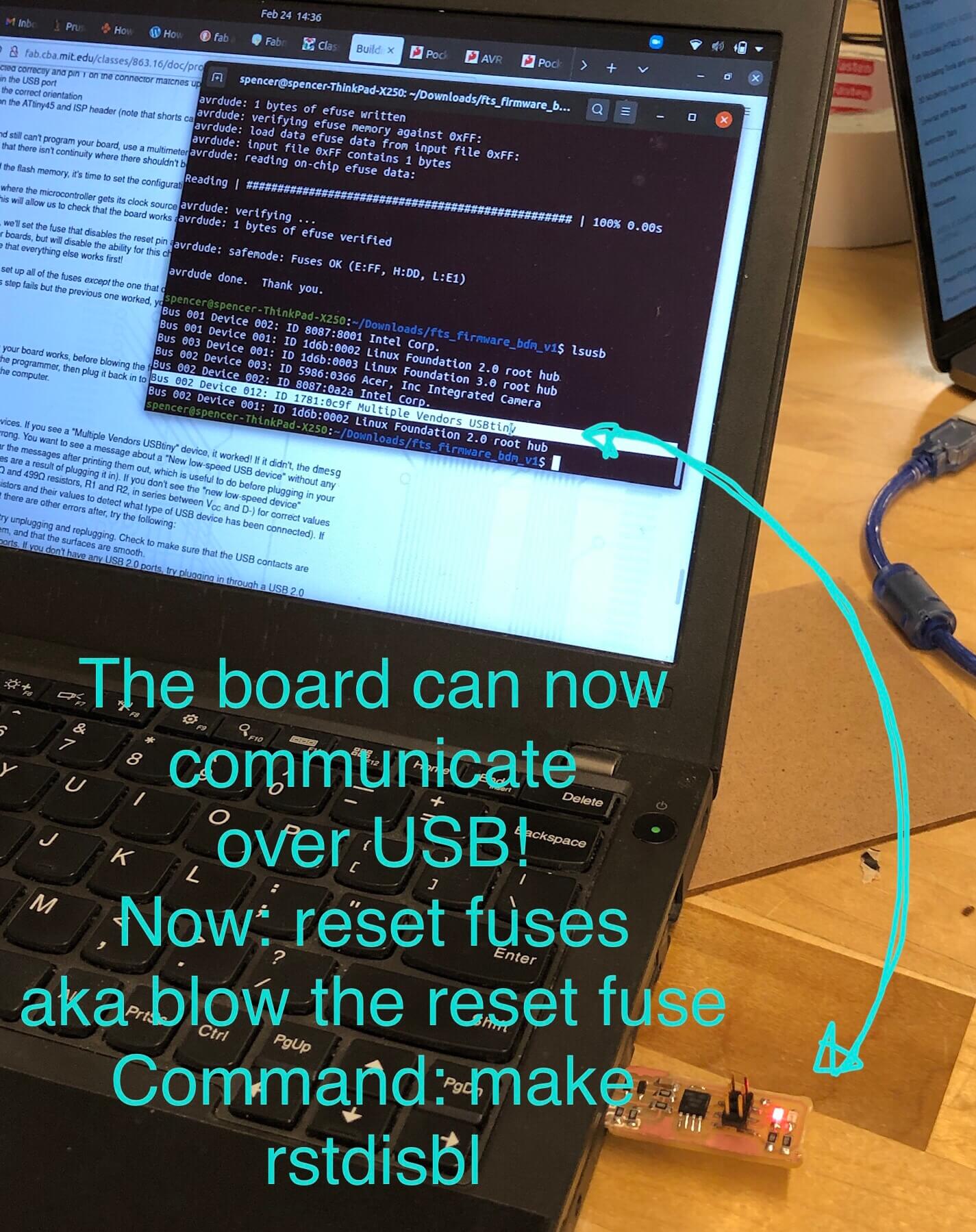 The board can communicate over USB! Sorry Neil, we shimmed the bottom of the board and stuck it right in there. Next is blowing the reset fuse, which sounds very dramatic! But it takes the form of an unassuming command: make rstdisbl. Ta-da! Now we can test this on a new FabTinyISP…
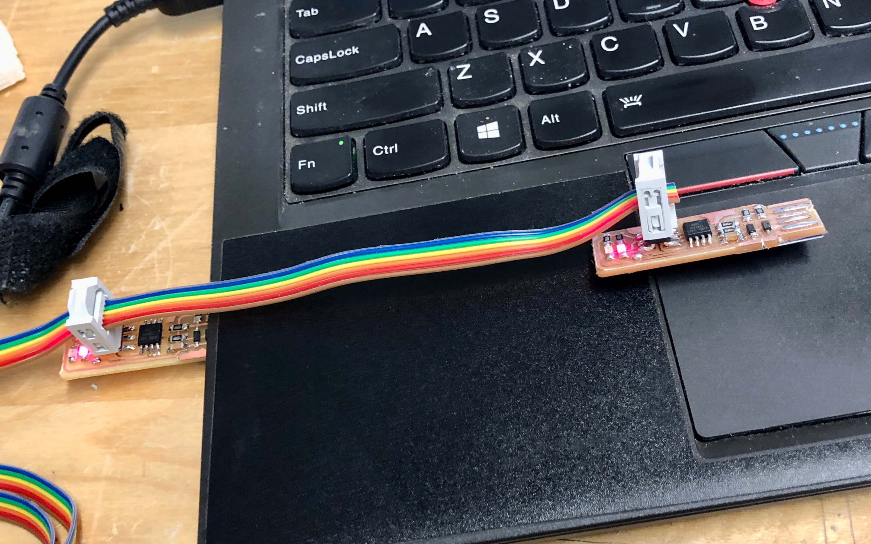 Getting the orientation right is important (board should be oriented in the same direction in reference to the connecting pins). The red LED lit up on the new board… promising!
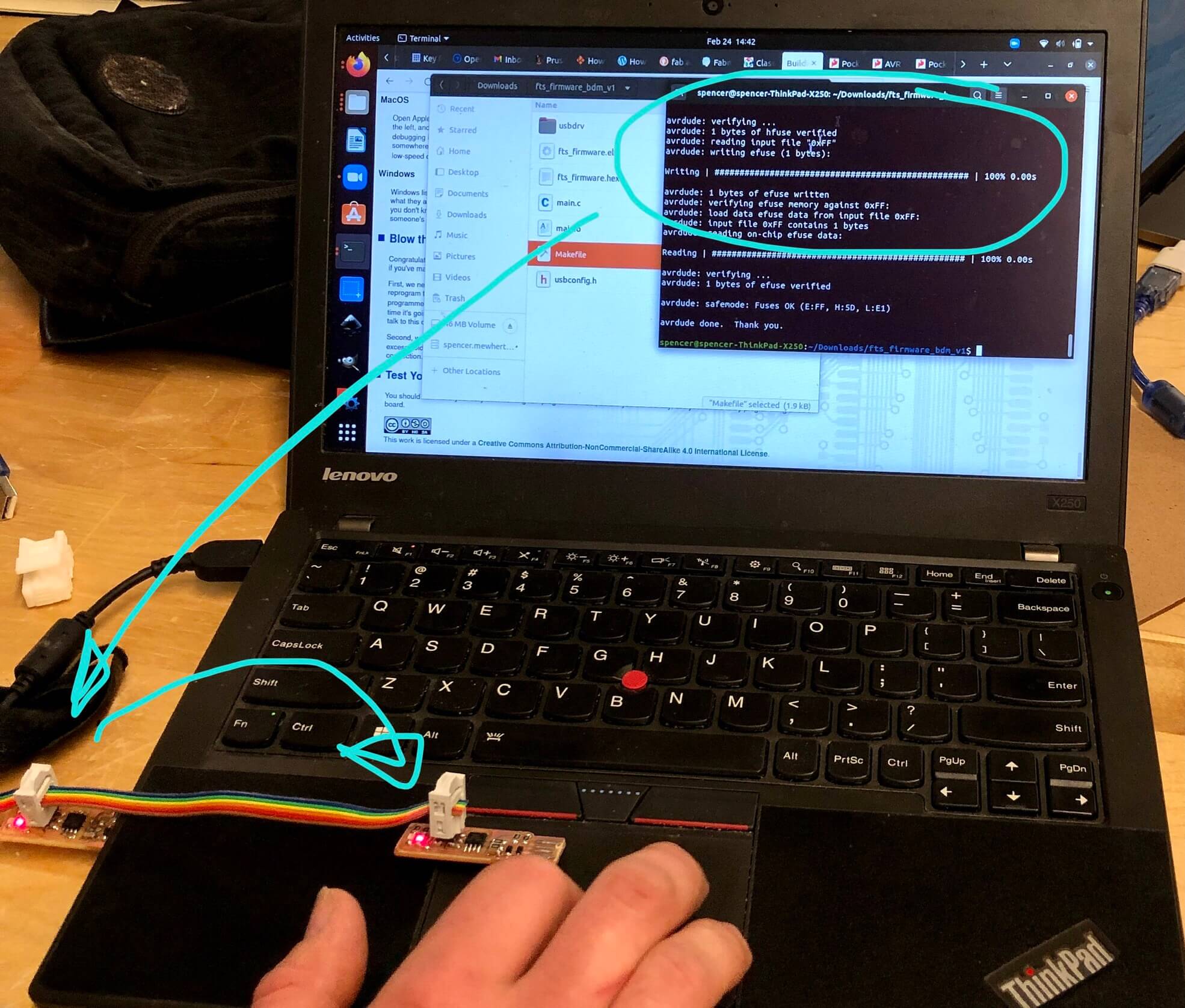 Successfully paired! The new board is now programmed and all we need to do is plug it directly into the computer and run the blow the reset fuse command, voila!
Lessons Learned
- Start by building up and programming a board that already exists (like Micro:bit)
- Don’t foreget about fritzing
- Bread boards are helpful for prototyping and testing circuits (but not terrifically robust, so store with care)
- Use double-sided tape to hold components in place prior to soldering (and label everything!)
- Have a clear work surface and calm environment
- Use a fine point soldering tip required (and a steady hand)
- Do not wear loose clothing, it can catch on tiny components set out
- Stay focused and don’t rush; do not get interrupted mid-way pulling out resistors from acro-bins or they will be destined for the purgatory box of unknowable components
- Solder a pad first (without the component); then, holding the component in place in the correct orientation with ceramic (ideally) tweezers, re-activate the solder with the iron and draw the solder up onto the leg of the component to ‘tack’ it down (like in MIG welding)
- Shiny = good; matte gray = bad (gray is an indicator that the solder was too hot and basically boiled, creating a craggier surface like spongy volcanic rock)
- Lead solder does work better than lead-free, but it’s worse for you
- Get a multi-meter (and probably a magnifying glass)! This allows you to determine the orientation of certain components if bands/markings are not present or easy to read
- Polarity (orientation) sometimes matters
- Orientation matters: diodes, some capacitors, ATTinys
- Orientation doesn’t matter: resistors, pin headers, ceramic capacitor
🧐 Lingering Questions:
- Is there a convention for orientation of components in carrier tape? Which side orients to the holes in the tape?
- Why do Diodes band the cathode (negative) side and Capacitors band the anode (positive) side? (<this sounds like a riddle, but I just really want to know why)