4. Computer Controlled Cutting and More CAD
This week: parametric design, vinyl cutters and lasers. This page will cover a deeper dive into CAD and the process going between parametric design (Fusion360) and fabrication (vinyl cutter and laser cutter) showing how I made a simple parametric construction kit (notch blocks) that account for kerf (width of the laser). I’ll also overview how we characterized our laser cutter attributes. Two main sections: Design and Fabrication.
Design
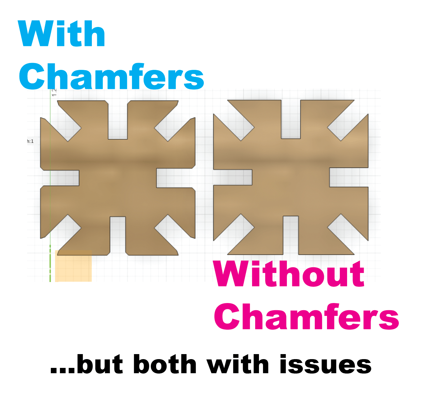
Design two versions of the notch block parametrically in Fusion360 to compare:
- one with filleted corners (for strength and tolerance forgiveness < is that a term?)
- one without
- parametric variables: thickness & depth
- How: in Fusion 360 > Parameters > User Parameters + > Thickness (inches) and Depth (inches) then assign segments to either “Thickness” or “Depth” and adjust in the parametric dialog box. Edit directly in Fusion 360.
- Notch Blocks can be created to make various forms: images to follow.
Fusion Confusion
Off to a … start. Then quickly realized there were issues with the parametric functions and constraints not carrying forward to the extruded design correctly. Upon deeper inspection two things to watch out for:
- Trim function can undo constraints even though it looks correct. There is really no need to Trim construction lines or geometries just to make it clean.
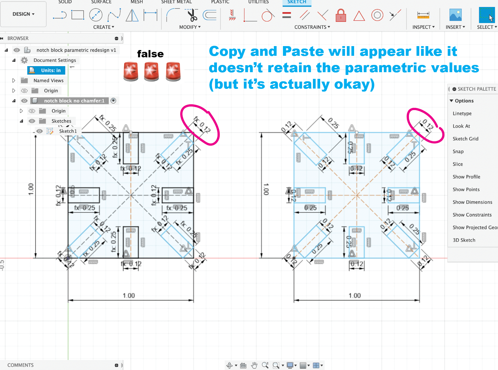
- Copy and Paste within the Sketch initially will look like it only retains the values, not the parametric function; but if you modify the parameters it will reflect in both original and copy. False alarm there, thought it was an issue.
Exporting a Sketch for DXF to open in Illustrator and send to Job Control (laser cutter)
The Magical Land of Rhino 🦏 and Grasshopper 🦗
I followed this tutorial with the mantra fake it till you make it. It’s pretty amazing that even in a step by step instructional video, every student will produce a different result! How cool. The idea of generating something like this from scratch feels very far away still, but it’s exciting to move sliders and iterate designs fluidly and … artistically.
I know many of the shapes I generated have naked edges 🤭 and that needs to be addressed before it can be decent for 3D printing. Rhino also creates a NURBS model and that needs to be converted to a Mesh for 3DP too.
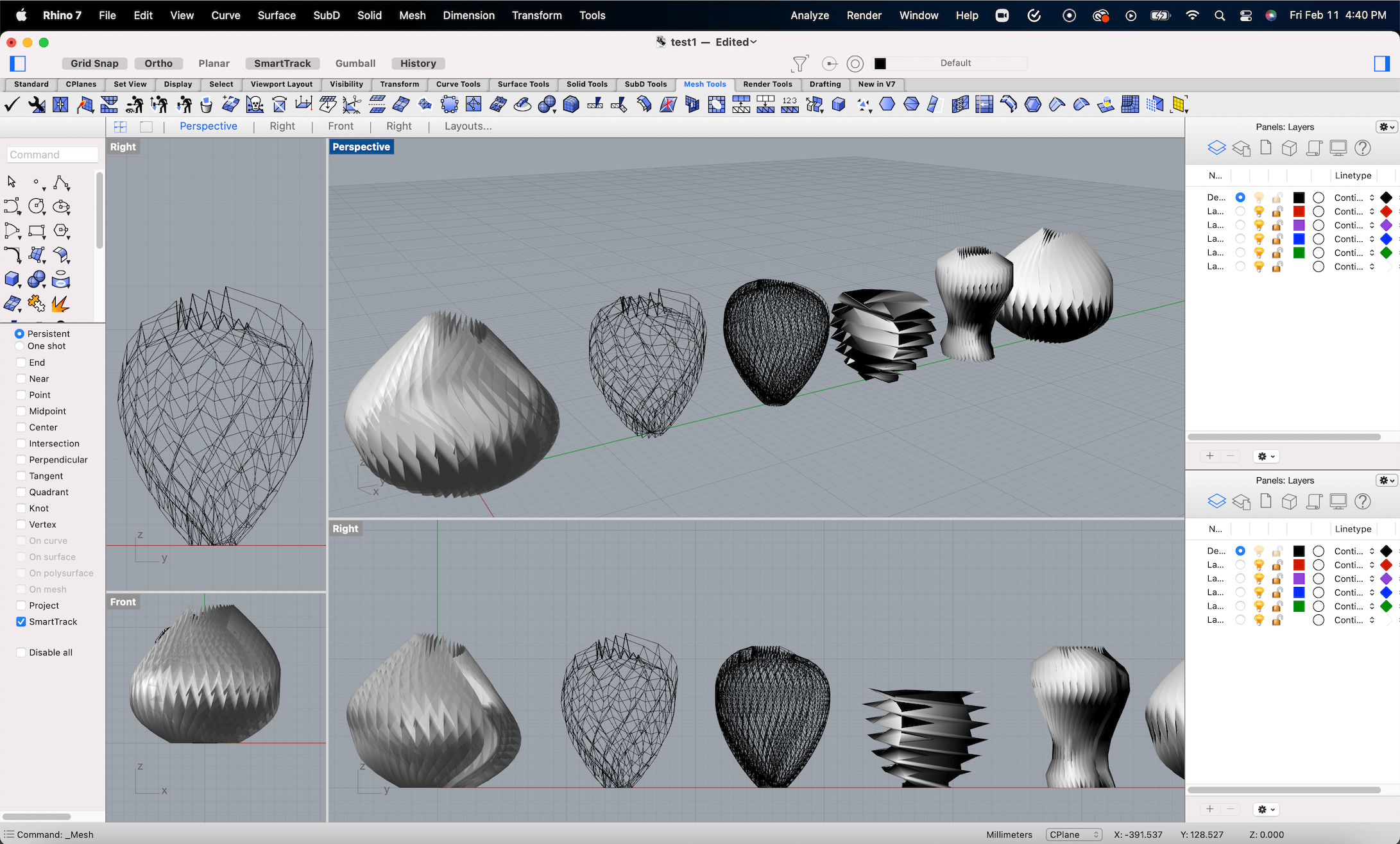 I designed these vases using Rhino + Grasshopper
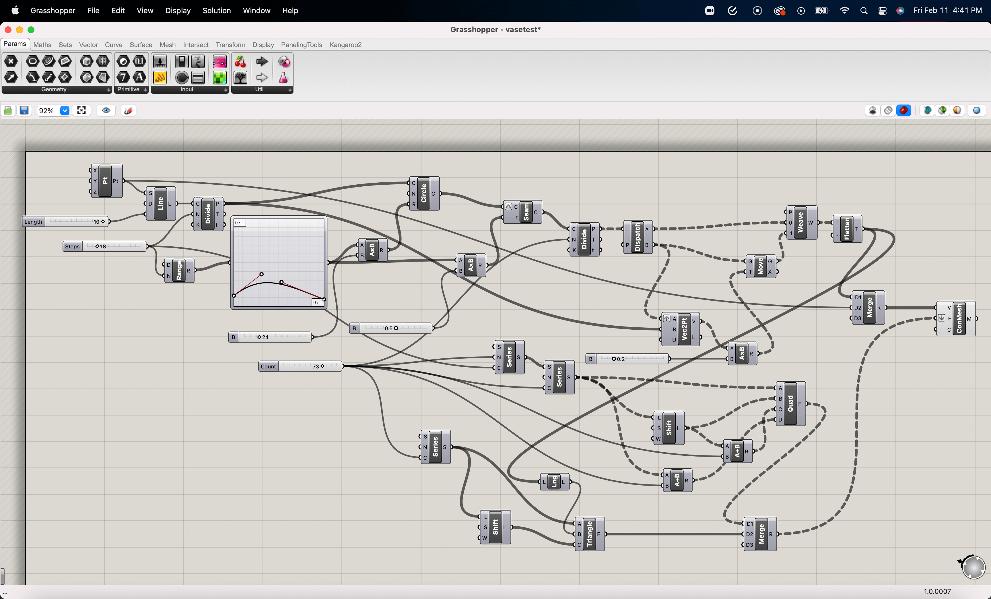 This is the Grasshopper string
Rhino demonstration by me on Vimeo.
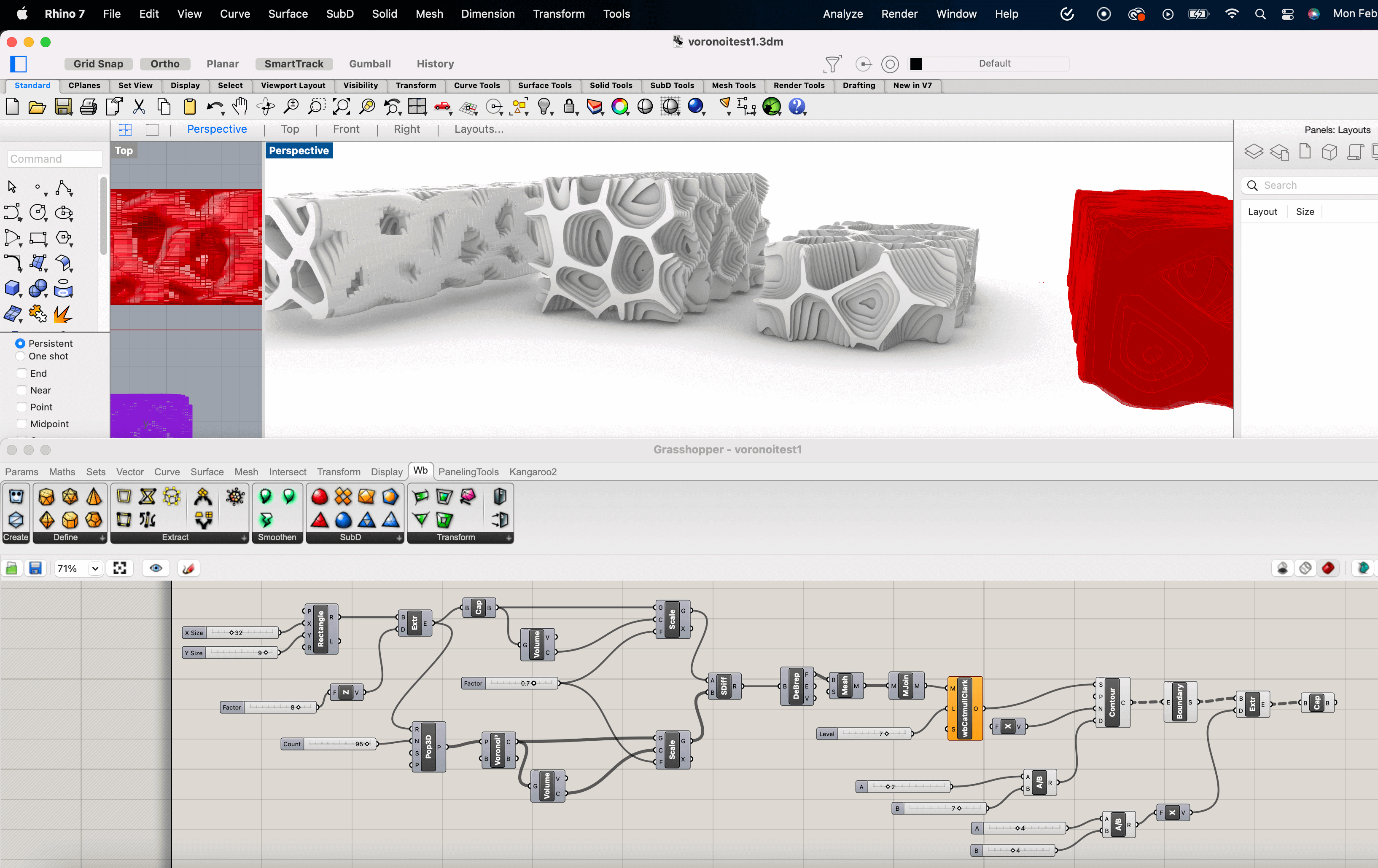
I wanted to learn more about Voronoi manipulations in Rhino using Grasshopper (<-what a sentence that is) so I watched this tutorial and made the following.
NURBS versus Meshes
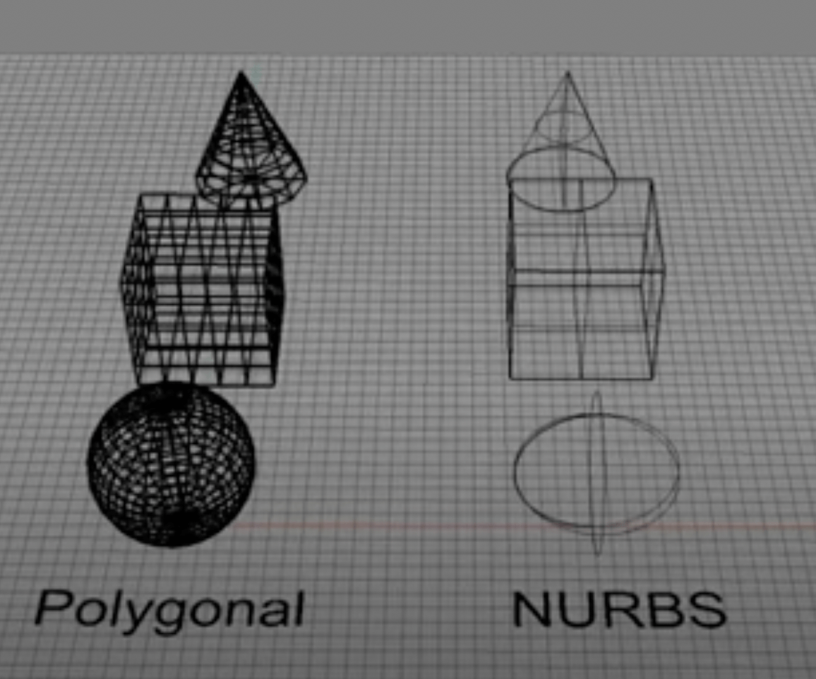
- Polygonal mesh = lots of trianges
- NURBS (non-uniform rational basis spline) is a mathematical model, kind of like vector graphics, and make for good renderings but need to be converted to mesh before exporting for 3D printing (STL file)
Fusion to Illustrator
Since you cannot send a job directly to the laser cutter from Fusion you need to export it for Illustrator as a DXF (I’m sure there are other ways, this is what I did).
Step 1: made mistake exporting the wrong sketch view which included all the construction lines in Illustrator
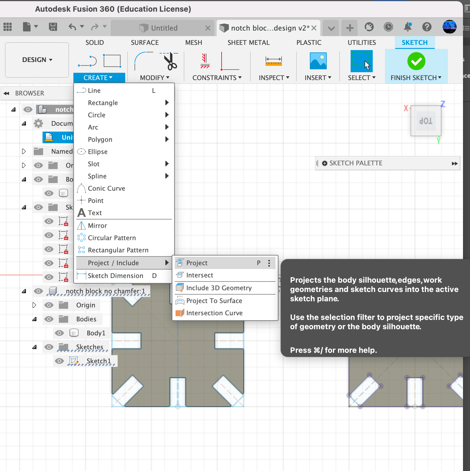
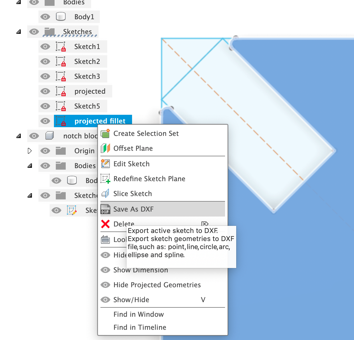
Step 2: watched this tutorial to learn how to do it correctly. Select the Object and Sketch view: then Create a Fusion Projection (purple nodes will be created to indicate this action was successful), then right click on that specific sketch and Export as DXF.
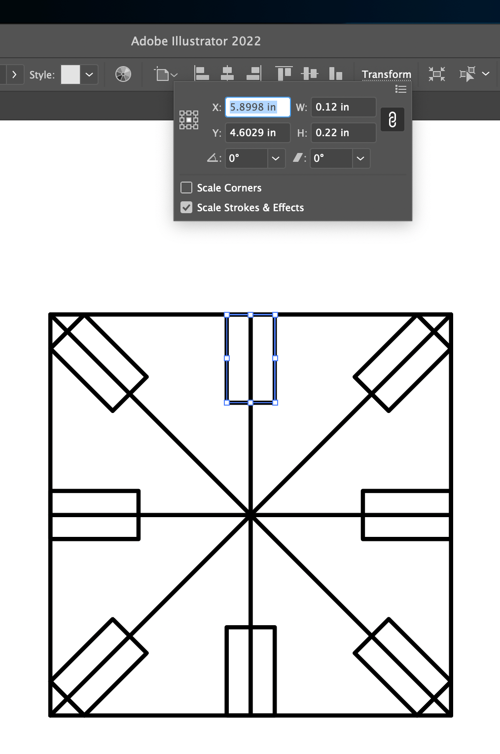
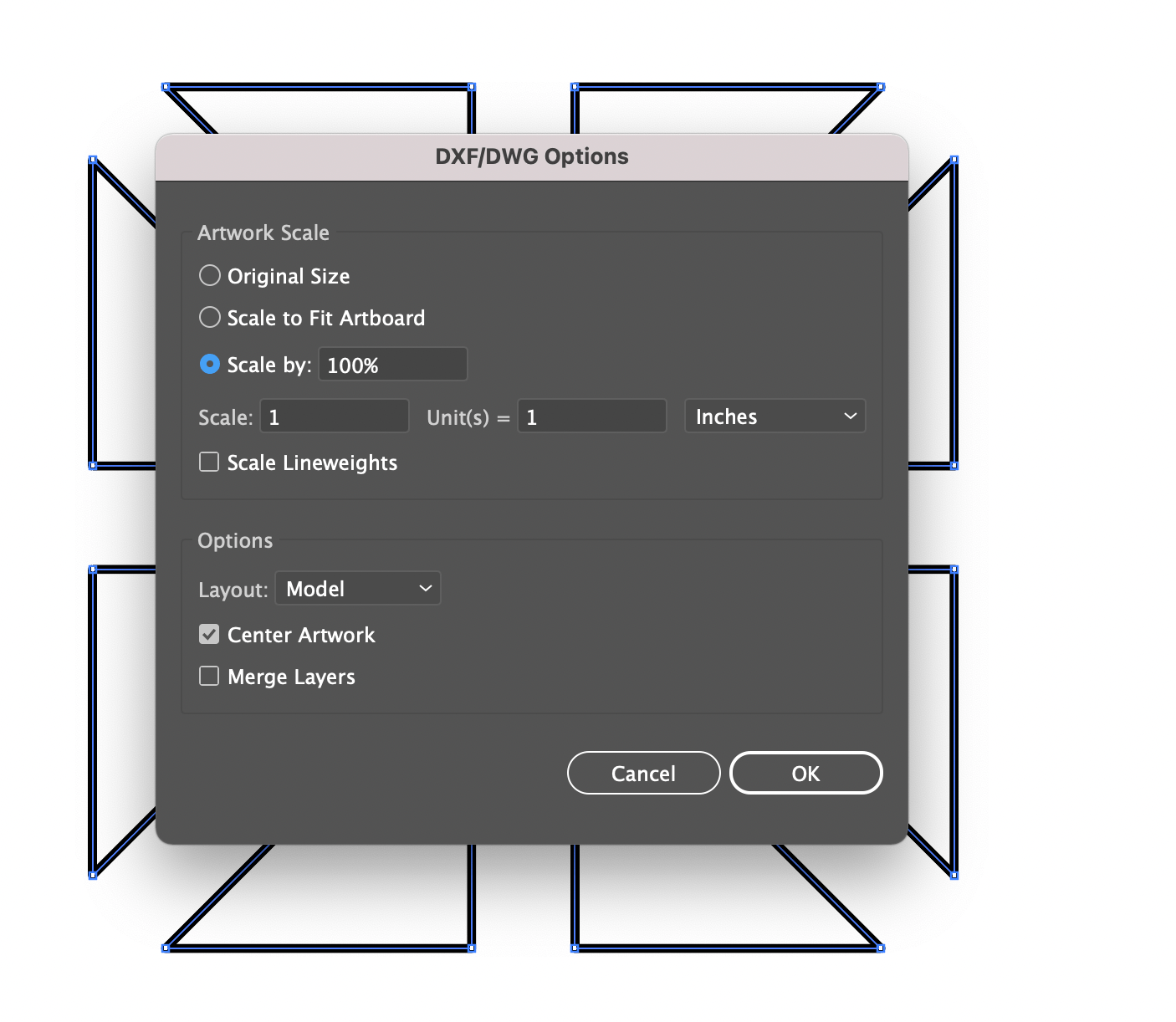
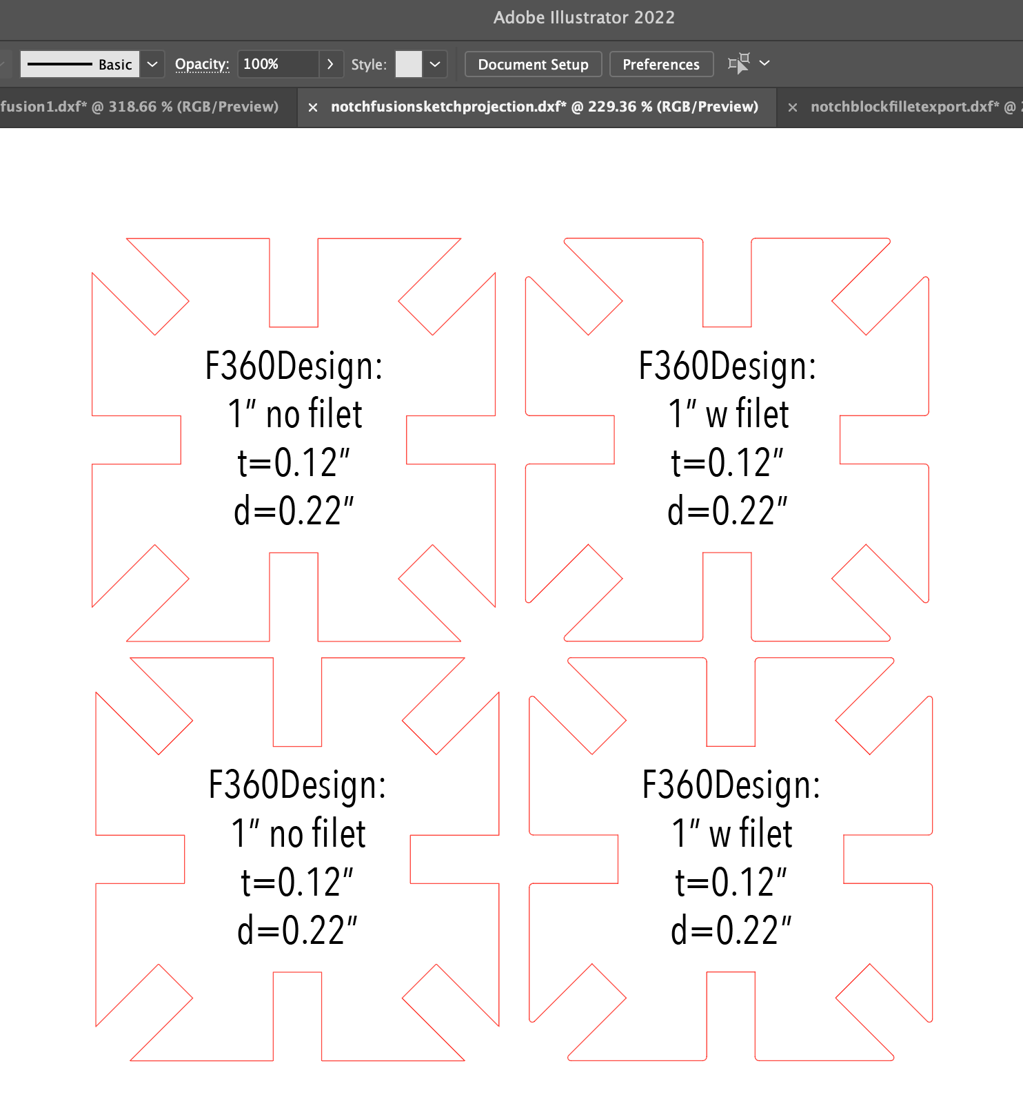
Step 3: created an Illustrator file that was scaled correctly and then added self-describing text to engrave onto the notch blocks so we can compare the design dimensions to the actual dimensions with calipers, and then redesign compensating for the kerf in Fusion and iterate until friction fit feels satisfactory.
- Set Stroke Weight: 0.01pt
- Set Stroke Color: RGB Red
🧐 Lingering Questions and Next Steps
-
I don’t know how to adjust the overall size of the notch block without also scaling the notches. If I want a 1.25” square notch block and want the parameters of the notches to remain parametrically fixed, how do I do that? Should I create another parameter for width? (Need to watch the recitation from 2/14/22 again)
-
From Rhino: once a shape is generated (like the sliced voronoi shape above) how do I export the layers for laser cutting? Can it also be an STL for 3DP?
-
Another Voronoi box tutorial in Rhino for future reference.
Fabrication
Getting to know the laser and vinyl cutter.
Group Assignment: Laser Characteristics
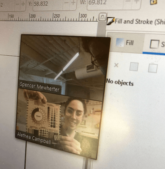
Dessault Systems down! Plan B: Alethea <3 who magically has a laser cutter in her home office, and we were able to run a test file to calibrate and measure the laser kerf (width of the laser beam) and other settings. How we measured kerf: designing multiple 1.00” rectangles and 1.00” circles in Illustrator; cutting them with the laser cutter; measuring the resulting void space with calipers to account for the exact thickness of the beam (divide by 2); take average over all rectangles. Then we used this information to design friction fits playing with the tolerance and accounting for variation in the plywood we were using. Results below:
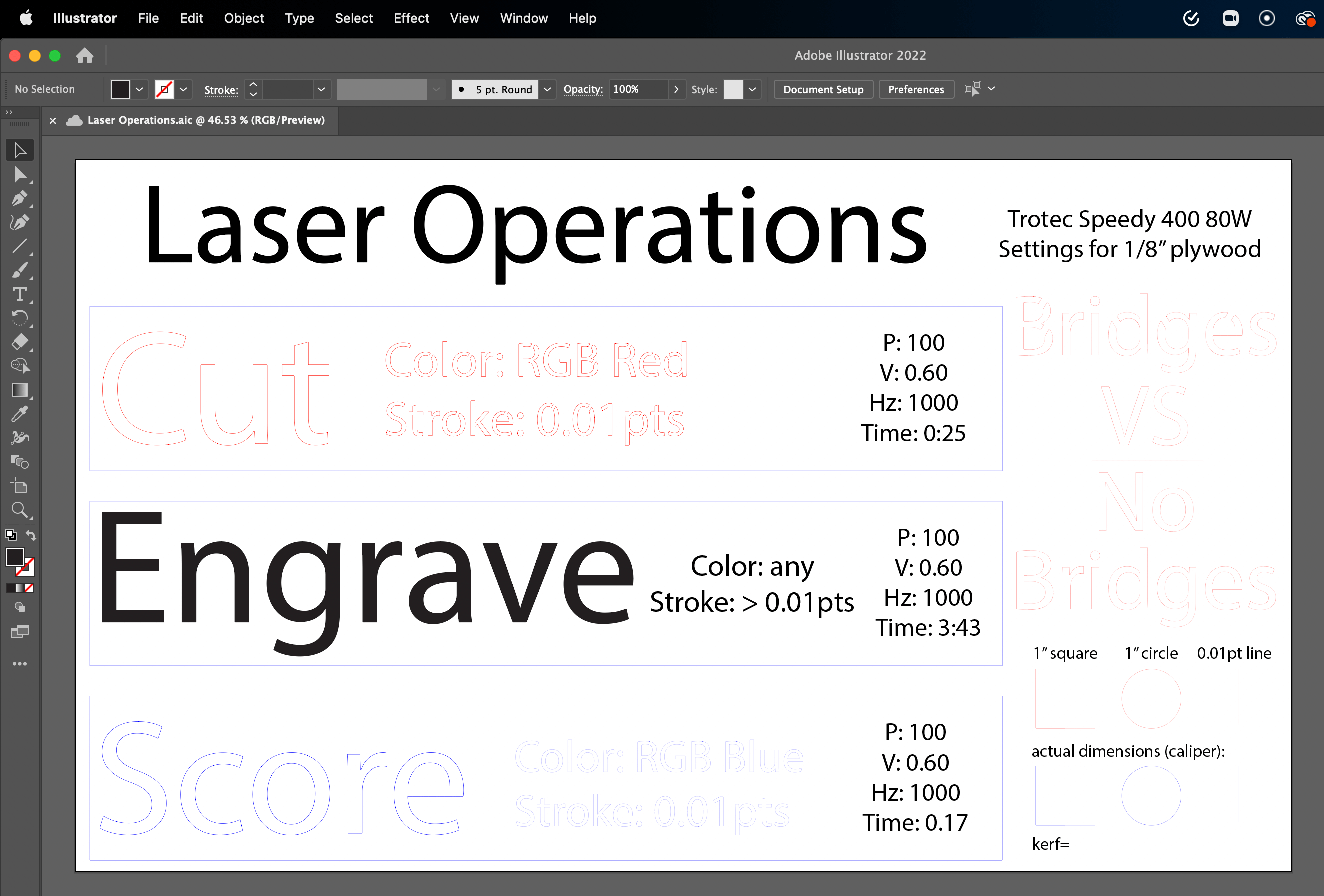
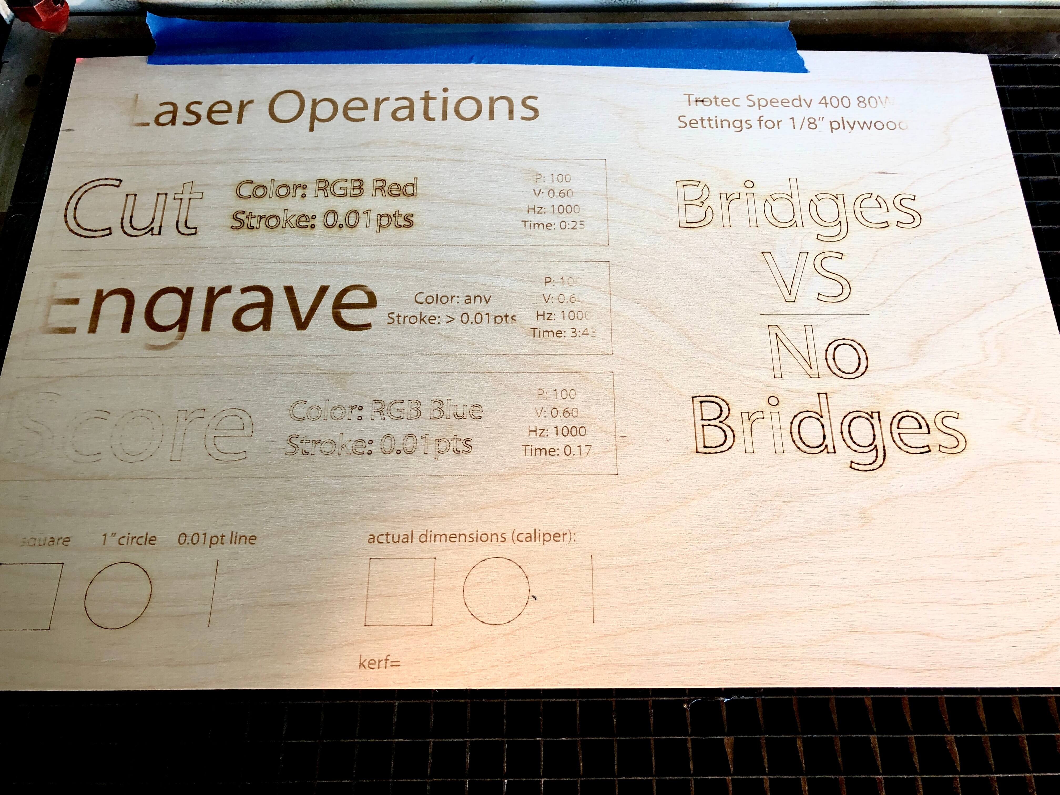
Below is a self-describing file I designed in Adobe Illustrator to demonstrate different laser operations:
Tuesday update: Dessault Laser is alive!
 Above is the first attempt at running the Cut, Engrave, Score file I created in Illustrator on some thick cardstock.
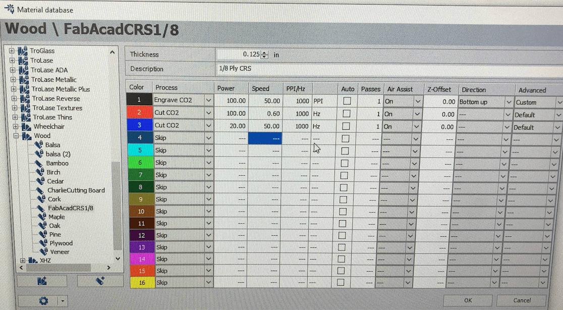
Some funniness; inconsistent engrave; needs to be color mapped correctly for scoring, which I did by adjusting the Material Properties in Job Control:
Color Mapping:
- Vector Cut: Stroke = 0.01pt RGB Red
- Vector Engrave: Stroke > 0.01pt any color (use black to get full power out of engrave setting)
- Vector Score: Stroke = 0.01pt RGB Blue
Dessault Trotec Speedy 400 80W Machine Attributes:
- Kerf Actual: 0.005”
- Kerf Compensation for Design: 0.0035”-0.004” (for a nice friction fit with 1/8” baltic birch plywood)
- Engrave CO2 1/8” plywood: Power 100, Speed 50, PPI 1000
- Cut CO2 1/8” plywood: Power 100, Speed 0.6, Hz 1000 (was not able to adjust to 500Hz)
- Score Cut CO2 1/8” plywood: Power 20, Speed 50, Hz 1000 (was not able to adjust to 500Hz)
Show your work:

Process Pics
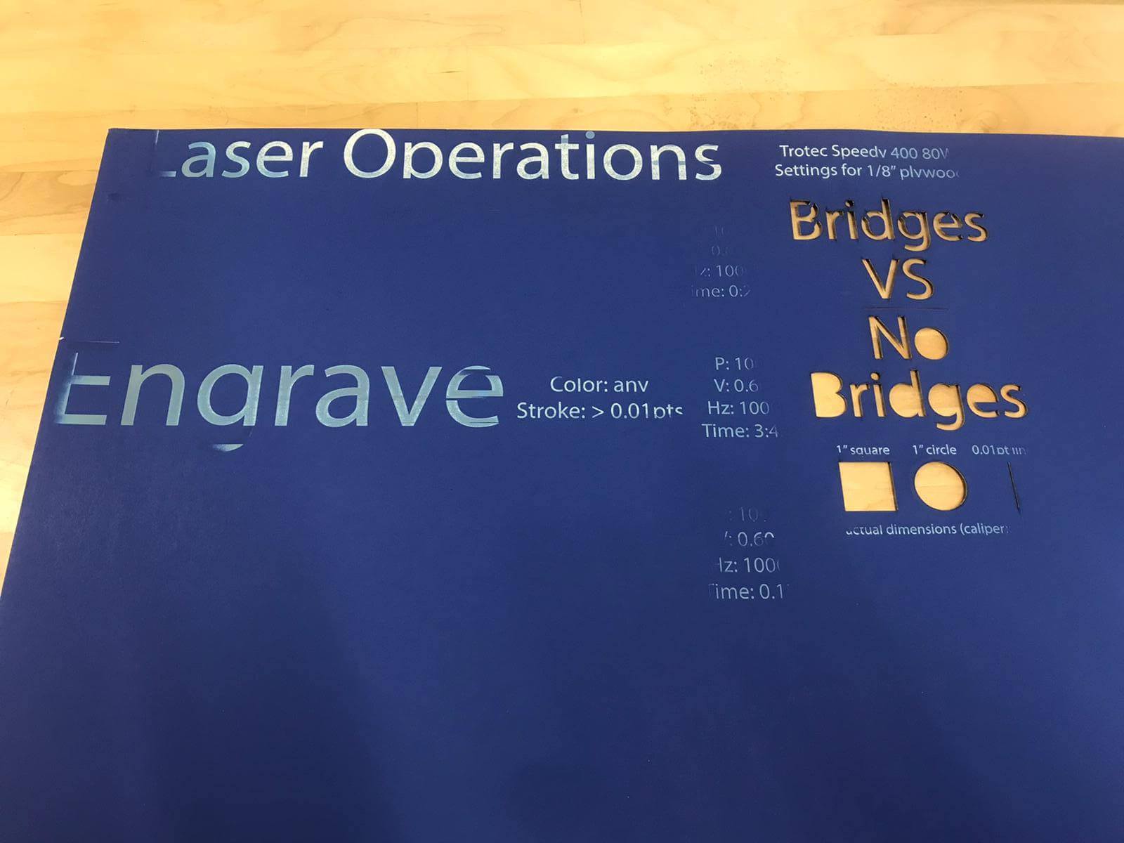
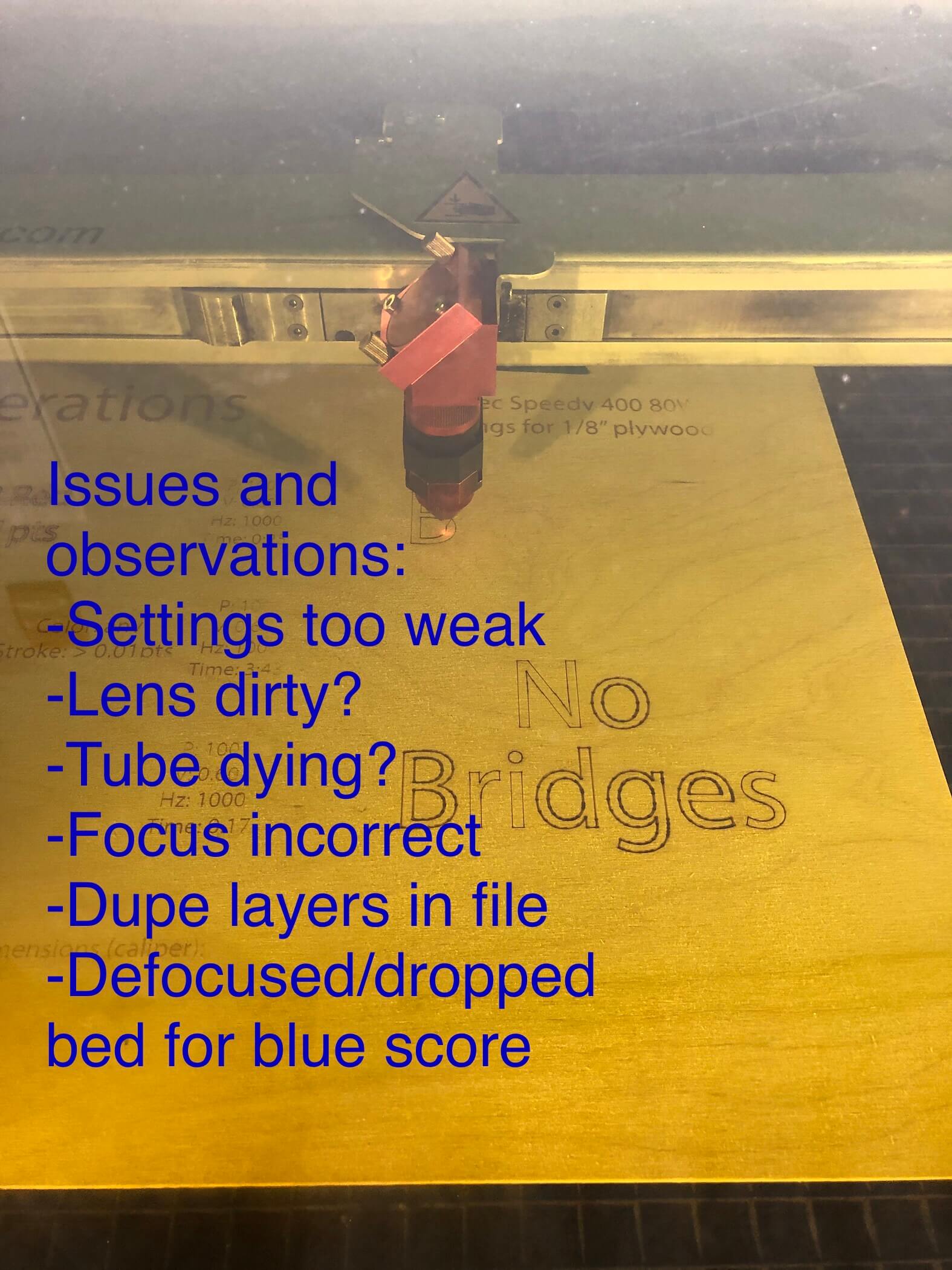 I paused the job several times to adjust focus and clean the lens, but it was woefully underpowered using the recommended settings for 1/8” ply.
 The fuzziness of the engrave is odd, and recurrs in the same location as it did on the blue cardstock we tried earlier. Interesting. Wins: I successfully color map the file to Raster, Cut, and Score, but the machine lowered the bed (and defocused) before running the Score operation (RGB blue was set to CO2 in the material settings-not Fiber) so that was weird.
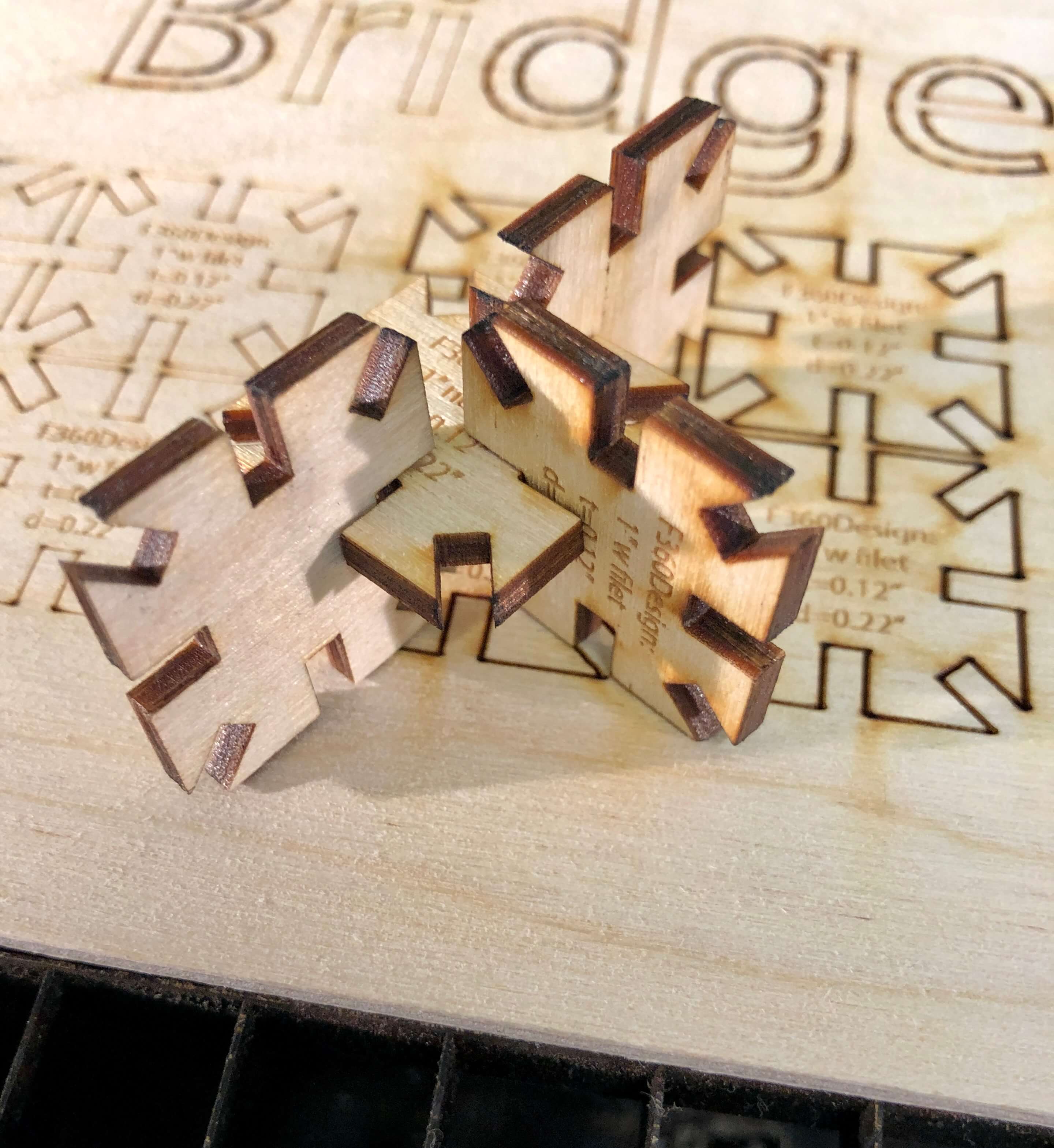 Finally! Some blocks! I had to reduce the speed significantly to achieve these cuts, but was able to get my friction fit blocks together accounting for the kerf of the laser.
 Here are more forms created with the notch blocks.
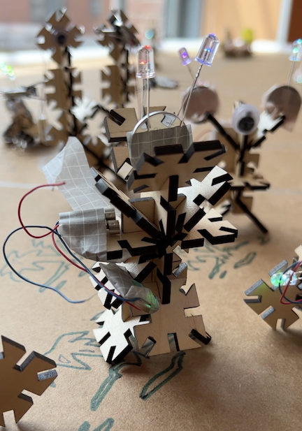
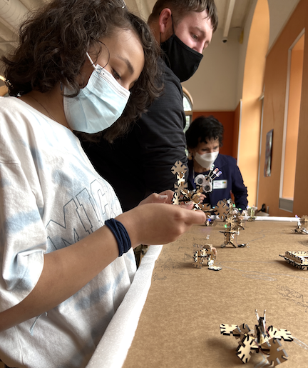 And in the real world students engaging with notch block plus mini motors and LEDs to create avatars.
Observations:
- Fillet cornered notch blocks caused the laser issues! It lingered in the corners, and formed the blocks with disperate passes; the “regular” notch block was a simple one pass cut, no issues. The segments are not joined-perhaps joining them will resolve the issue? Need to test this! (see video for fillet weirdness)
- Fuzzy/inconsistent engrave: laser tube is dying ☠️, lens was dirty, and focusing gauges were unlabeled (!) so it was not clear which was for Fiber and which was for CO2 (I labeled them after using the wrong one, you’re welcome future friends!)
- For the Laser Operations file: duplicate lines were somehow generated causing the laser to make multiple passes; will need to address this (Fab Universe: has anyone written a script to fix this issue?!)
Vinyl Cutter
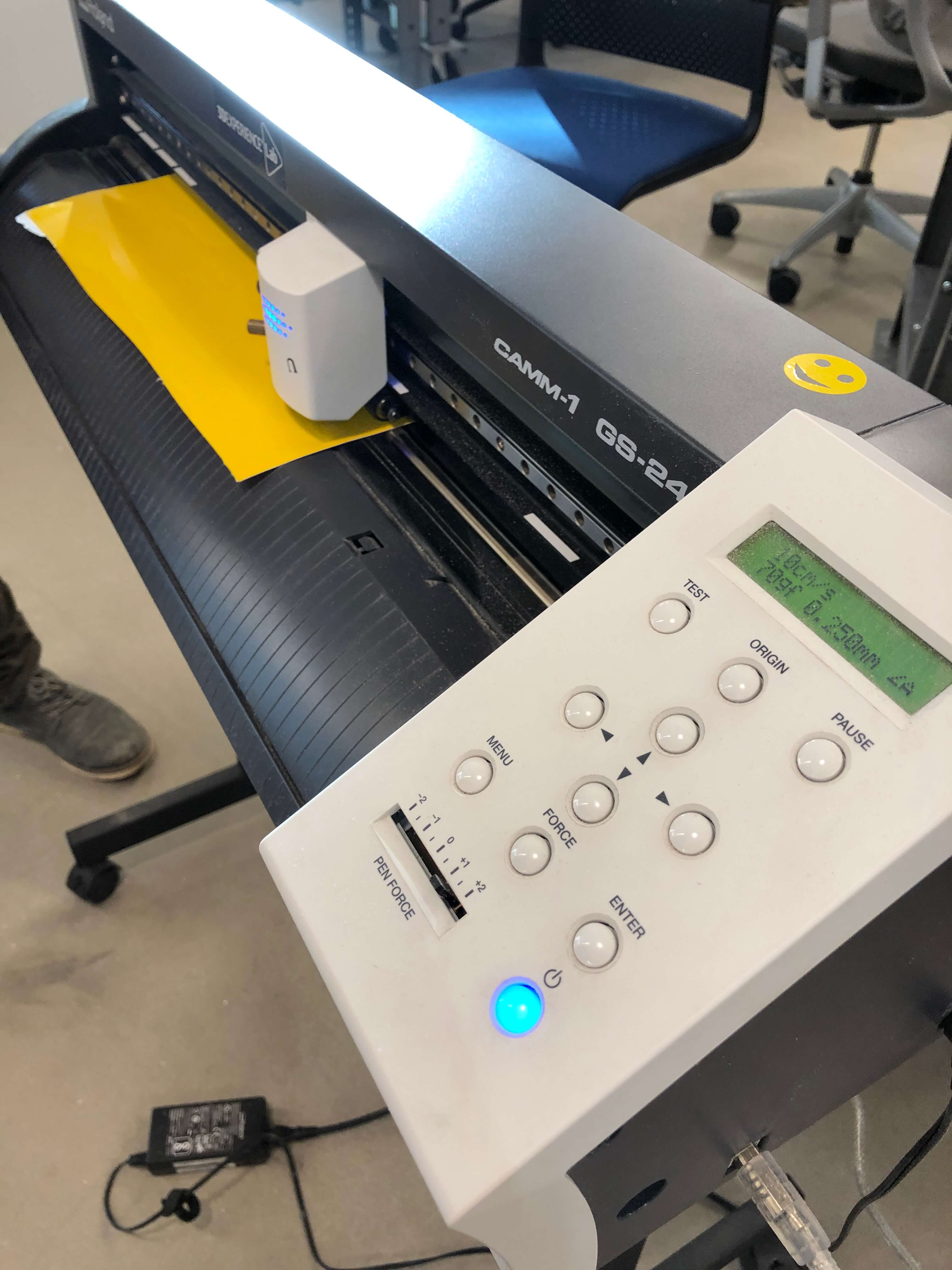 Here is the Roland vinyl cutter at the Fab Lab. Confusing interface and annoying print drivers.
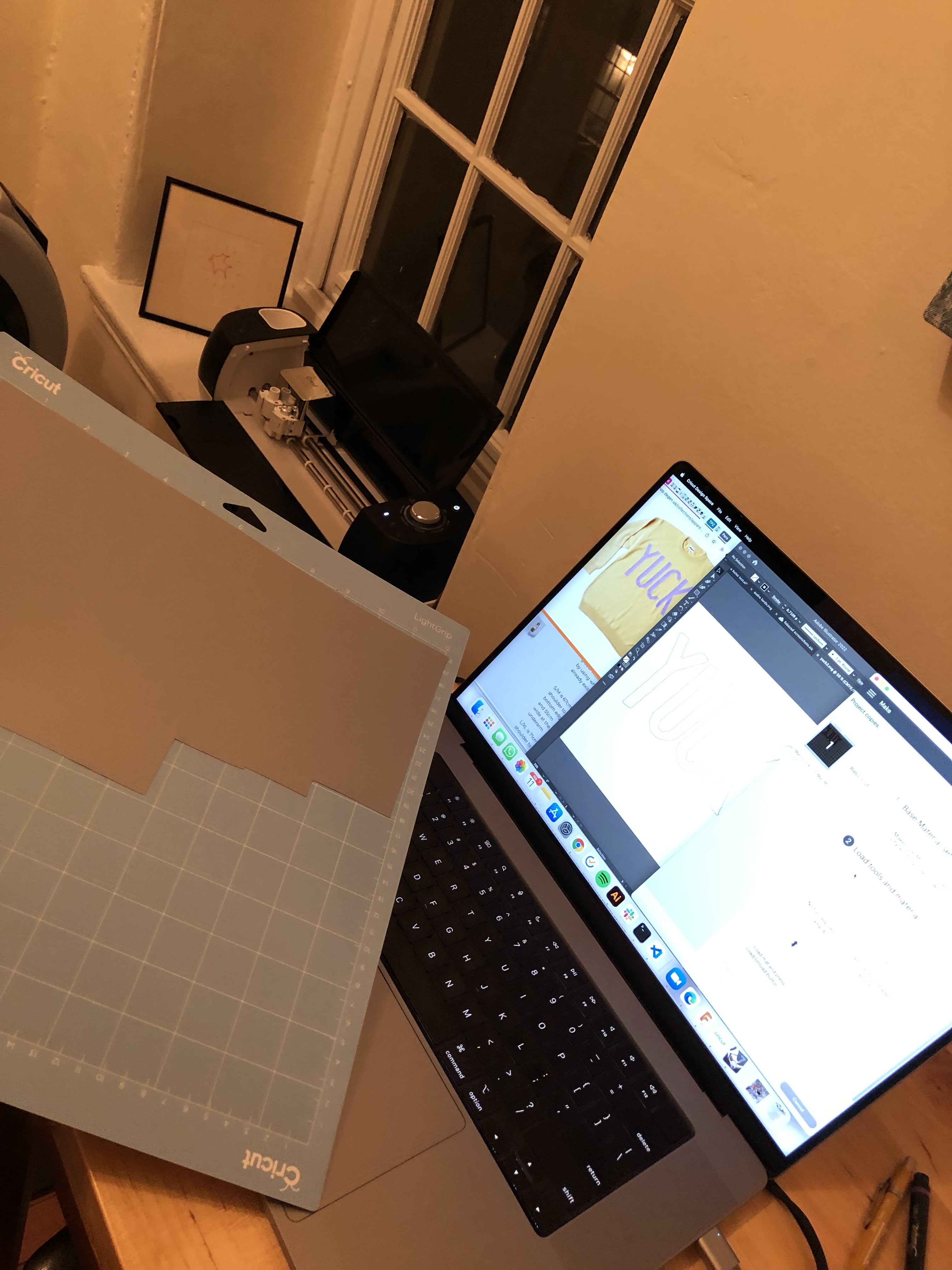 Here is my personal Cricut in action; a remarkably simpler machine with great UI and a lot cheaper.
Step 1: In Illustrator create vector lines: Draw using the Pencil Tool OR vectorize an image (jpg or png) using IMAGE TRACE; EXPAND commands. There is an art to the Image Trace Panel parameters: typically, when preparing a design for cut lines:
- Start with a high resolution high contrast image
- Run Image Trace Mode: Black and White
- Threshold: between 50% and 75% but this varies a lot depending on source image
- Advanced: Paths: set high
- Advanced: Corners: set high
- Advanced: Noise: set low
- Advanced: Ignore White
Shout out to Lindsey Degan Yuck verbage inspired by Lindsey’s amazing knit sweaters
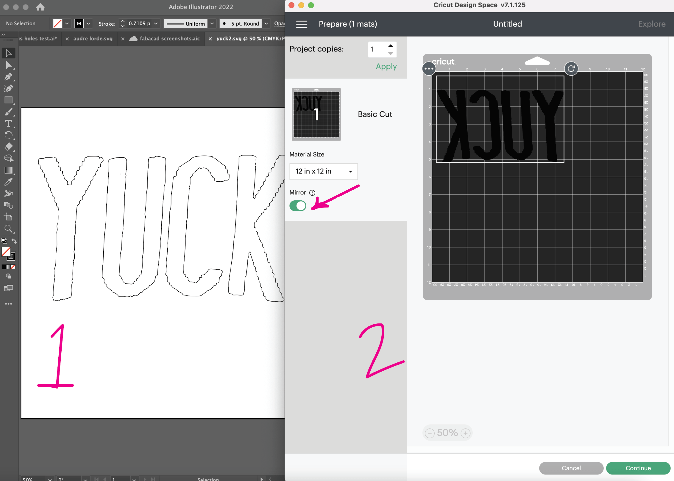
Step 2: Save As SVG file and bring into Cricut Design Space. MIRROR the image if cutting on heat transfer material.
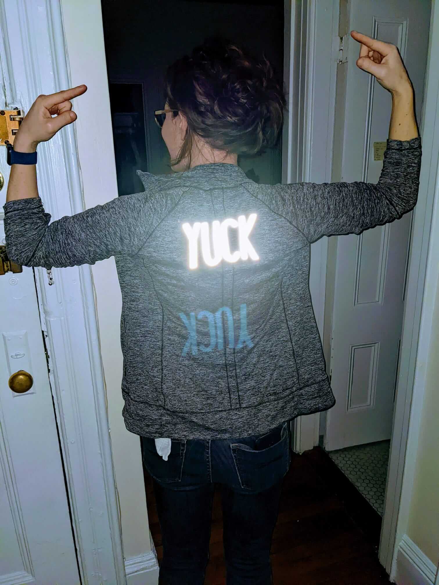
Material: Siser Featherlight Heat Transfer Reflcetive Vinyl
- Be sure to put the material BACK side UP on the mat for cutting
- Fine point blade
- Settings should have enough pressure to cut through the back material but not the transfer material (Cricut makes this far easier than most roll to roll vinyl cutters with a knob and material settings; for this project I selected Heat Transfer)
Step 3: Weeding
Vinyl Weeding by me on Vimeo.
Step 4: Ironed on and ready for action. Used high temperature setting + firm pressure approx 30 seconds (pressing, not moving); do not use steam (will mess up the vinyl adhering properly)
Design Files
- Adobe Illustrator Laser Operations
- Notch Blocks from Fusion imported into Illustrator
- SVG Yuck file for Vinyl Cutter