4. Electronics Production
The Japanese concept of monozukuri - the enjoyment of making things - is key - from the Roland web site.
This week we started to learn about electronics production. This week we focussed on the art and craft of soldering and milling printed circuit boards (PCBs). I made progress on my final project, buying a 270 watt solar panel from wallapop and making improvements to the solar cooker I am making my lunch with. I continued working on laser cutting and finishing up projects from previous weeks.
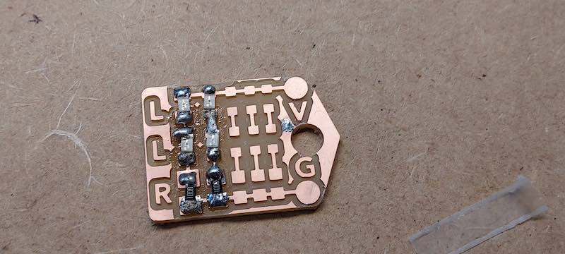
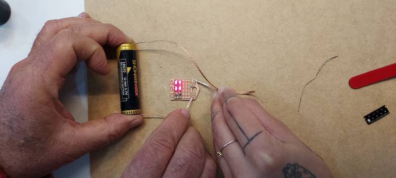
Here are my finished, programmed and functioning boards for this weeks assignment.
Solderng and PCB Milling Demos
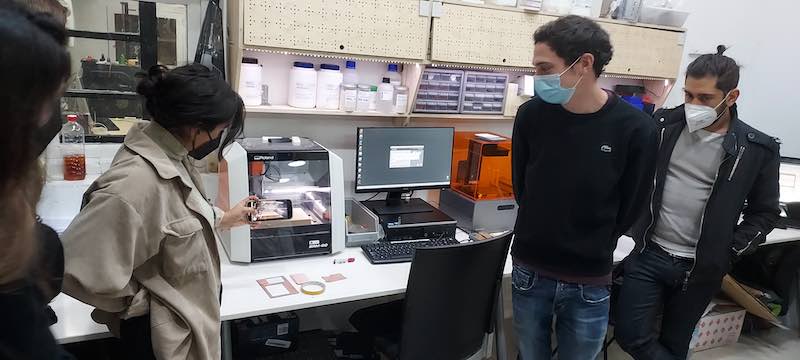
After Neil’s talk, we had hands on demos of soldering and PCB milling.
Soldering
We were given a bare circuit board and some components to solder on to it. On examination, the board consisted of rows of two diodes and a 1000 ohm current limiting resistor. My workshop partner Kai and I tested the circuit with an 18650 lithium ion battery after soldering.
We practiced using solder wicking tape to desolder. These tiny smd components just require a little bit of heat from the iron. Our iron was not adjustable, it has a fixed tip temp of 350 deg c. We used a pair of tweezers to hold the components. It took a bit of trial and error to figure out how to hold the component, the solder and the soldering iron accurately.
I had soldered before but SMD components are new to me.
PCB milling
First you need to be given a design or prepare one in Kicad. Then export the PCB as an SVG. Mods uses PNG files. Open the SVG you created in Inkscape. You need to change everything that is black into white and everything that is white into black. The mods program leaves what is white and mills away what is black.
Inkscape process
- Create separate layer for the background.
- Draw a rectangle around the design, fill it gray.
- Change everything in the PCB layer to white ( you can still see it with the gray background).
- When everything is white in the PCB layer change the background to black.
- Export as a PNG using 1000 dpi to get the right size.
Next we had a demo on using the Roland mill. The end mills we use are tiny - 1/64th inch for traces and 1/32nd inch for milling around the exterior of the circuit. The 1/64th bit is very easy to break. When I opened mine, it slipped out of the package and rolled on the floor and the tip broke.
Heres the work flow, summarized by classmate Adai:
TO GENERATE PCBs!!!
modsproject.org
“.png” or “.svg” files (always black and white) better to use “.png” always use at least two files one for the circuit path and another one for the out cut, if need holes use a third file for the drill. always export in 1000 dpi to get good quality image ¡check size of the image!
open program
srm-20 mill
absolute position
open program set up (visual scripting nodes)
select png or svg files
black part is the part that the machine is going to mill
white part is the one the machine is going to keep
define settings (set pcb defaults)
select the tool that is going to be used
will change settings in (mill raster 2D)
important to de the Z correctly to not break the tool if goes too deep
important to do the Z correctly to not cut less material than desired
offset number –> number of times that the tool is going to pass arround the path if = 0 cleans all the copper that is not going to be used
offset stepover –> 0.5 overlaping the tool of the previous path
direction –> use climb
view –> pre visualize tha paths
For pcb traces - in mods, change the bit size to 1/64, change speed to speed =3, all other presets stay the same
For cutting a hole or an outline, change bit size to 1/32, change speed to 1.5, change the Z dept to 1.75, all other presets stay the same
in visualization
check the path is correct and is not leaving two components together.
speed –> 3 for path cutting // 1.5 for outline cutting
origin –> 0,0,0
jog height –> distance the tool is moving when not cutting DON’T GO TO LOW!
home –> 0,0,30 remember to change the Z value to not scratch the PCB when finish
CONNECT THE OUTPUT TO THE SAVE FILE
File is generated automatically
Assignment
From the course web site:
group assignment:
1. characterize the design rules for your in-house PCB production process
2. extra credit: send a PCB out to a board house
individual assignment: 1. make an in-circuit programmer that includes a microcontroller:
- extra credit: customize the design, mill and stuff the PCB, test it to verify that it works extra credit: try other PCB processes
Group Assignment
Group assignment web site is here, also summarized below.
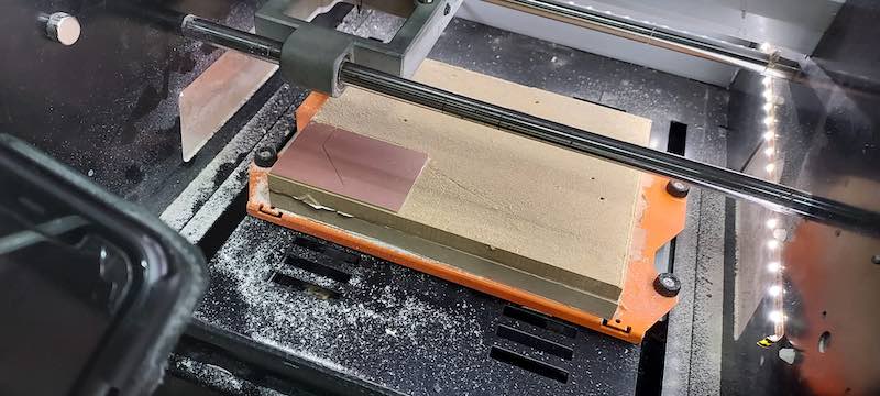
Our assignment was to charactaerize the parameters of the Roland SRM 80 milling machine.
Here are the specs of the Roland SRM-80 (it’s the same Japanese based Roland company that has been making musical equipment since the 70’s)
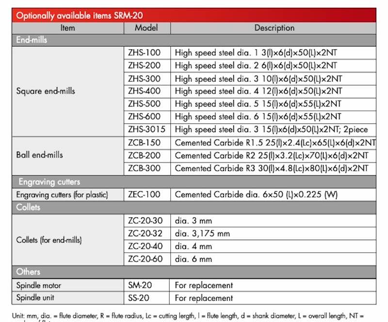
Here are the options available:
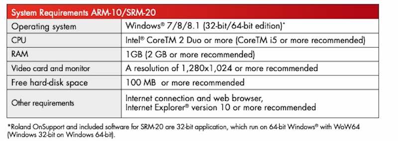
Here are the computer requirements:
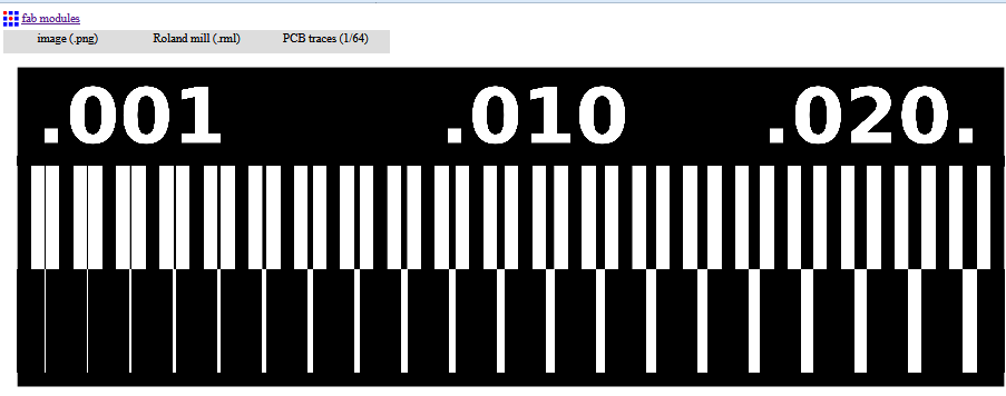
Next we printed two copies of this test file, one using climb and one using conventional milling.
We ran this file through modspriject to creat the RML fle that the Roland needs.
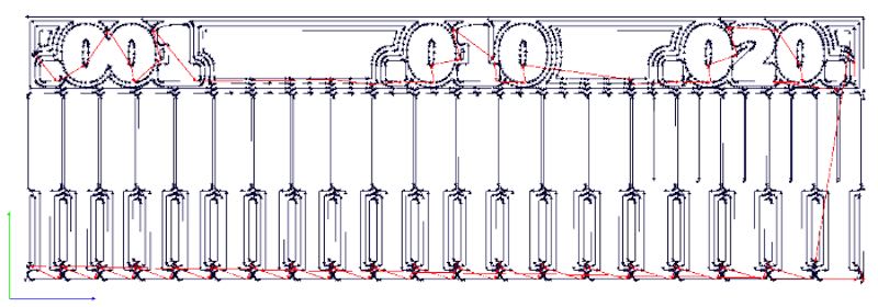
Here’s what the toolpath that modsproject creates looks like. You can use this to look for places where traces are too close:
Here’s what happened the first time we milled the file - we forgot to check the size and it was too big.
Final image of the test file is on the group assignment page (link above)
Individual Assignment
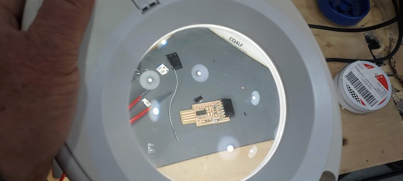
The assignment is to make a programmer for a microcontroller. We are given PNG files for programmer printed circuit boards. I need to mill the printed circuit board, stuff it (solder the components on it), and test/debug it.
What is a programmer for anyway?
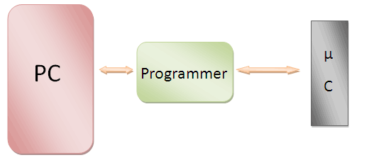
A programmer goes between a microcontroller and a PC to allow the PC to send instructions and data to the microcontroller. It allows connection of the microcontroller to a PC via a USB or serial port. Some microcontroller families, like the ESP line by Expressif Systems, have programmers built in and can connect directly to a computer USB.
There are two main manufacturers of microcontrollers that we will use in class - Microchip and Esxressif.
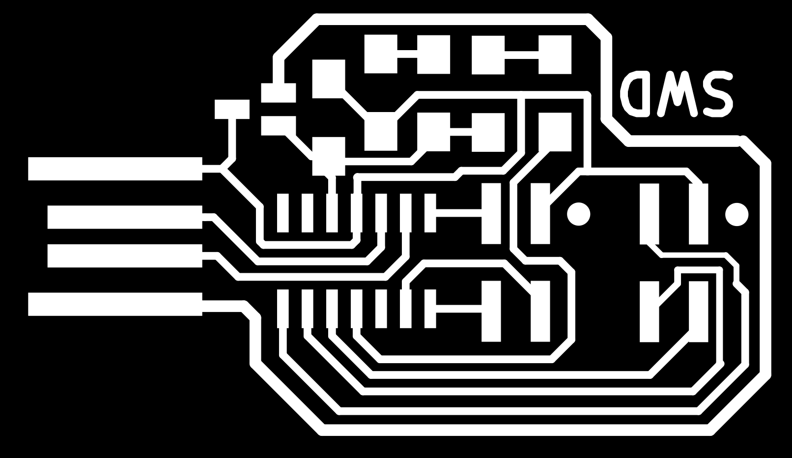
Here are the design files (PNGs) we were given for the programmer PC boards we need to make:
Each board has two PNG images that are used to create the files for making it - a file for the interior of the board and a file for the exterior border of the file. Each of these uses a different bit - a 1/64 inch bit for the interior traces of the board and a 1/32 incn bit for cutting the exterior outline of the board. Here’s what the PNG files looks like for the SWD D11C programmer used for programming ARM chips:

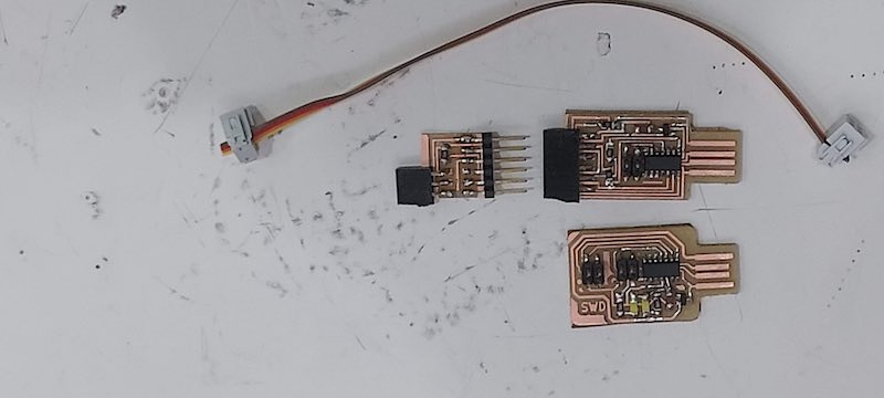
In addition to the SWD11C programmer, I need to make two bridges, a Serial (FTDI) D11C and a Serial to UPDI that converts the serial(FTDI) bridge into an UPDI programmer. FTDI is a Scottish company that owns the intellectual property to serial interfaces.
The PNG files need to be converted into files that the Roland mill can use (RML file extension). We use a web site called modsproject that was developed by MIT/Neil.
Instructions for using modsproject are detailed above. I am still finding this flow diagram programming and work flow a bit confusing but intriguing and want to explore other ways it is used.
Took a look at what the RML file looks like:
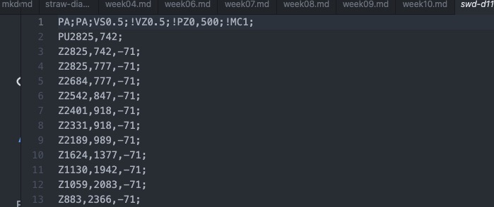
Looks like a bunch of xyz coordinates.
Now that I have the files, it’s milling time!
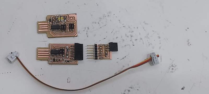
The boards work and are programmed.
Here’s a list of issues I had while finishing this assignment:
-
Ruining two boards with bad soldering techniques that pulled traces off the board. Had to make three boards. Turns out the solder I used at home was bad. I couldn’t solder with it even if I used flux. When I brought it in to the lab even Josep couldn’t solder with it. Finally had great success with the solder from the lab. My solder was thicker.
-
Broke a 1/64 mill during the milling process because it was milling too deep. It seemed to be a problem with hwo I was setting the Z axis, I was pushing down on the board too much when setting the z axis.
-
Spent 10 hours at home over a weekend trying to solder the boards - my solder was bad and I ruined the second board I made.
-
Openocd would not work on my mac - never did get it to work even with help from Oscar. Josep helped me program the SMD11c programmer using EBDG on his PC. Then I used the Arduino IDE to program the other board using the programmer.
Here is what the EBDG command line looked like:
edbg -b -t samd11 -pv -f build/Demo.bin
Here are the EDBG options, they go after the ebdg command line - it is not sensitive to the order of the options.
EDBG OPTiONS
Usage: edbg [options]
Options: -h, –help print this help message and exit
-b, –verbose print verbose messages
-x, –reset
-e, –erase perform a chip erase before programming
-p, –program program the chip
-v, –verify verify memory
-k, –lock lock the chip (set security bit)
-u, –unlock unlock the chip (forces chip erase in most cases)
-r, –read read the whole content of the chip flash
-f, –file
-t, –target
-l, –list list all available debuggers
-s, –serial
-c, –clock
-o, –offset
-z, –size
-F, –fuse
Fuse operations
format: [actions] [section] [index/range] [value]
[actions] - any combination of ‘r’ (read), ‘w’ (write), ‘v’ (verify)
[section] - index of the fuse section, may be omitted
if device has only one section; use ‘-h -t
[index/range] - index of the fuse, or a range of fuses (limits separated by ‘:’) - specify ‘:’ to read all fuses - specify ‘*’ to read and write values from a file
[value] - fuses value or file name for write and verify operations - immediate values must be 32 bits or less
Multiple operations may be specified in the same command. They must be separated with a ‘;’.
Exact fuse bits locations and values are target-dependent.
Overall impressions from this week
Overall, like Fabacademy in general so far, it was a pretty frustrating experience but I learned a fair amount and got some practice milling and stuffing boards.
I am surprised to find lots of buggy software, extraordinarily bad user interfaces for humans, and lots of problems getting my computer (2010 Macbook pro with OS Catalina installed using Catalina Patcher by dosdude) to work with the software and hardware we are given.
Simple Inverter Design for my Final Project
The voltage pf the panel is 30 volts dc at the peak power point. The toaster oven operates at 220 volts ac but it is a resistive load so it can take either ac or dc. It can operate at a lower voltage with loss in power output.
Power is related to the square of the voltage (V**2/R), so if the voltage is cut in half the power is one quarter. I am planning on making an inverter to convert the DC at the panel to AC and then boost the voltage with a transformer.
Higher voltage will allow the power to be transmitted with less loss. The resistive load of the toaster is somewhat insensitive to the quality of the voltage and frequency of the inverter. I just need to match the peak power point of the panel to the resistive load of the inverter.
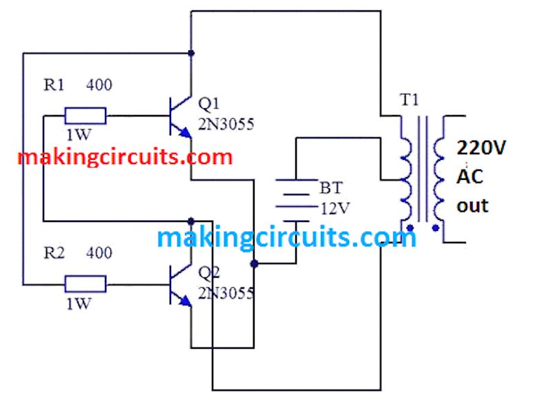
Here’s a very simple inverter circuit that uses just two power transistors, two resistors, and a center tapped transformer. Will see if I can use MOSFETS instead of transistors and keep the simplicity of the circuit. I like that this circuit is analog - you don’t need any microcontrollers.
I hope to mill this PCB in the next week or so. I bought the transistors and am looking for a transformer.
Useful links
- Here is a link to Professor Edurdo’s great tutorial on using the Roland SRM-80 milling machine.