9. Embedded programming

The Digi-Comp 1 - A Plastic Mechanical Computer
I got one of these for Christmas when I was 10 or 12 (1967-69), Sears sold them. It implements mechanical analogs of logic gates and other elements of digital computing and could run rudimentary programs and even games.
Quote of the week:
“I live and work in an open source computing world from the ground up..I started by being able to dual boot in windows or linux, when I couldn’t finish my work in linux I would shift to windows. For a long time now I have been completely in linux” - IAAC professor Victor Berberian
Overview of This Week
This week we explored computing architectures and the difference between microprocessors/computers and microcontrollers/embedded programming. This week brought to my mind a question that has come to me before - is computation a fundamental property of the universe, and what is the relationship of computation to information, entropy, matter and the development of order and structure in the universe.
The programmer is a translator from a computer USB port to the SWD(serial wire debug) communications format used by the SAMD11c for bootloader installation.
The bootloader then allows the controller to communicate via USB to a computer for further programming.
The lectures by Victor and Eduardo helped me understand the differences between microcontrollers for embedded programming and microprocessors for computers. Each chip is a package of functions implemented in silicon. Microcontrollers are meant to control things in the real world, often in a program that runs in an infinite loop. Microcontrollers have many of the peripherals they need integrated on the chip. Microprocessors are designed to be the heart of a general purpose computer and sometimes have peripherals on separate chips.
Serial communication formats include:
- UART/USART (Universal asynchronous receiver transmitter) - USB, one to one
- SPI - SD memory card interface
- I2C - Several devices communicate over two wires, connects up to 0-255 devices like sensors.
SWD and UPDI are 1 or 2 wire communication formats used for programming and debugging microcontrollers. Debuggers let you look at the internal state of things in microcontrollers as they run in order to debug problems.
Assignments
Individual assignment
Read the data sheet for your microcontroller
use your programmer to program your board to do something
extra credit: try other programming languages and development environments
Group assignment
Compare the performance and development workflows for other architectures
The group assignment website is here
Individual Assignment

I programmed the button-led board to do various things and I explored setting up and programming arduino Uno (ATmega328P microcontroller) and ESP32 boards and a Raspberry Pi.
I struggled to get the button-led board functional - in the end I had two problems.
-
There is a problem with macs recognizing boards on the Arduino IDE and in using the workflow for OpenOCD (Open On Chip Debugger) or EDBG (Embedded Debugger). I was able to install bootloaders with the Arduino IDE, and I got people with PCs to help load bootloaders in my boards. My mac is unreliable in recognizing my boards, works every time on PCs. I have a 2010 Macbook Pro 13 inch with a hacked version of OS 10.15.7 Catalina (Apple blocks Catalina form working on older macs that are capable of running it. MacOS Catalina Patcher by DosDude1 allows older macs to run Catalina and seems to have very few compatibility issues). I am working to get an older PC that I can run linux on and plan on testing the Arduino IDE on my Raspberry Pi. (later note - this ended up being a cruel joke was a complete waste of time, lots of time )
-
My board powered up but would not work. Continuity tests during build and after completion indicated hat everything was connected properly. I had to ask Josep for help. He reflowed solder on many joints in the board and it just started working. The mini usb traces are very small and he suspects this was the issue.
Once the board was working I had a few more issues. For one, the communications protocol in the arduino ide needs to be set to two wire.
Eventually I found a blinkly light sketch, changed the pins to the ones on my board, loaded it with the arduino IDE and boom! the light started blinking!
Blinking LED 1 sec on 1 sec off
I changed parameters for LED on and off and observed the results. I experimented with a PWM like dimming of the light by changing the pulse on and off times.
Blinking light 100 msec on 100 msec off
Next I loaded an led/push button sketch and played with the parameters of it.
This finishes documentation for this week’s assignment (make the board do something). I will document my explorations with Arduino Uno, ESP and Raspberry Pi as I get caught up with past assignments.
Review data sheet for the Samd11c
The 981 page data sheet for the SAMD series microcontrollers from Atmel is here
Here’s a summary:
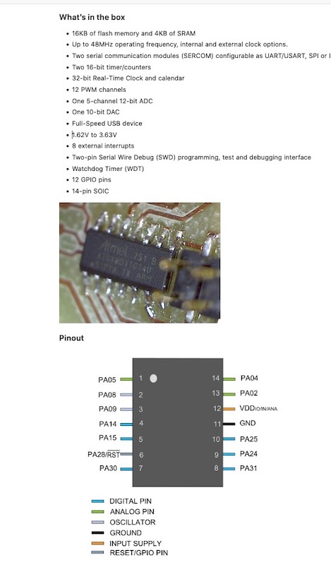
After reviewing the Samd11c specs, it looks like I will need the 20 pin version for my final project (Solar Electric Toaster Oven) as I’d like to have more inputs and outputs than the 14 pin package allows.
Group Assignment
You can find the group assignment here
Raspberry Pi and ESP 32
I also worked on programming the arduino uno, the raspberry pi and the ESP32 using boards I have. Got the arduino to work but had problems with my mac and the ESP32. Got the ESP to be recognized but could not get software to upload. The ESP is pretty complex and can do things like wifi right on the board. A “hello world” program got the names of all the wifi networks in the area.
Blinky Light/Button Code for This Week
Got this code from Tutorials Point here and modifed for the pins on my board. My board used pin 14 for the LED and Pin 4 for the button. I then modified the code to change the on off times of the LED.
Blinky LED light Sketch
 // the setup function runs once when you press reset or power the board

void setup() {  // initialize digital pin 13 as an output.
   pinMode(14, OUTPUT);
}

// the loop function runs over and over again forever

void loop() {
   digitalWrite(14, HIGH); // turn the LED on (HIGH is the voltage level)
   delay(1000); // wait for a second
   digitalWrite(14, LOW); // turn the LED off by making the voltage LOW
   delay(1000); // wait for a second
}


**Blinky Light and Button Sketch**

Got this code from the Arduino website [here](https://create.arduino.cc/projecthub/SBR/working-with-an-led-and-a-push-button-71d8c1)


``` c++
//The light turns on when the button is pushed.

//This code uses variables for the button and LED pins so I only had to change them in 1 place.

const int BUTTON = 4;
const int LED = 14;
int BUTTONstate = 0;

void setup()
{
  pinMode(BUTTON, INPUT);
  pinMode(LED, OUTPUT);
}

void loop()
{
  BUTTONstate = digitalRead(BUTTON);
  if (BUTTONstate == HIGH)
  {
    digitalWrite(LED, HIGH);
  }
  else{
    digitalWrite(LED, LOW);
  }
}