Final Project
Final Project (tentative)
Basics
A modular and maze with electronic features to be used in robotics training tutorials and competitions.
Problem description
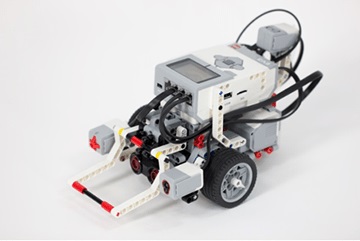
I work in the Robomania section at our National Science Centre. We run robotics demonstrations, workshops, camps and clubs. One of the best kits for teaching robotics is the Lego Mindstorm EV3 kit. One of our most useful challenges is getting students to build and program a robot to solve a maze and pass through it. The current maze we use has some major problems:
-
The maze itself is bulky and heavy, making it difficult to transport when we run the activity at remote locations
-
The maze design is fixed. We give students free range to use whatever programming techniques they want to “solve” the maze. Rather than come up with an intelligent program that can solve a variety of maze configurations, some students use a brute force technique (e.g. programming the robot to go 10cm forward, then turn left 90°, then 30cm forward, turn 90° right......). This requires a lot less thought about the robots algorithm.
-
Difficulty is fixed because the maze is fixed. When we encounter particularly talented students who come up with a working solution quickly, we can’t adjust the mazes diffculty to give them a harder challenge.
-
The maze is a little plain. It’s part of a robotics challenge, so having just a wooden maze with no shiny techy features isn’t as visually enticing as it could be.
Solution
A Modular maze that can be: - Easily broken down and set back up for easier transport. - Reconfigured into various layouts to add more challenges. - Has electronic features to make it more exciting. (electonic timer and barrier).
Schematic
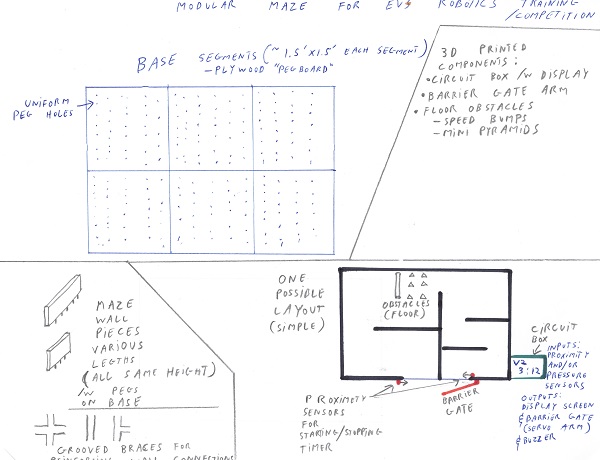
-
Maze base will be designed like a peg board with uniform holes thoughout. They will be made of individual pieces (likely plywood) about 1.5’ x 1.5’ that can be joined together to make the larger whole base.
-
Maze walls pieces will be made of plywood or MDF with appropriately spaced pegs on their base to fit into the holes on the base. The wall pieces will be made to the same height, but varying lengths so that they a variety of layouts can be achieved.
-
Grooved brackets will be cut to reinforce the walls to add more stability to the chosen layout. Wall pieces may need to have grooves cut into their ends to accomodate brackets.
-
Grooved paths along wall pieces for clean running of electrical wires for sensors/servos. (potential future upgrade)
-
Electronic control. Conected to proximity sensors (or presure plates) that control the timer and barrier gate. Servo for barrier gate. Display for timer.
-
3D printed mounting brackets for sensors and servo(s). 3D printed electronic box for display and circuitry.