9. Mechanical and Machine Design
Objectives
- Group assignment: Design a machine that includes mechanism, actuation and automation.
- Build the mechanical parts and operate it manually.
- Actuate and automate your machine.
Urumbu X-Y flexure machine
Automatic Sun-avoidance blinders
Introduction
Most of the work is depicted here and also on Maxime’s website and Jason’s website.
This week, Jason and I decided to improve the Urumbu project. The idea of this machine is to use flexure to decompose X and Y axis and to be able to actuate them with separate actuators that do not need to move with the other one (contrary to classical CNC machines for example).
We also wanted to make a “machine-day” where we built a machine in a single day!
Planning and collaboration
We have two weeks to develop these machines. And we have two machines to make. To organize our work, Jason and I decided to split the work between “mechanical” and “electronics” stuff, while working in a spiral. In practice, that means that we brainstormed together, then developed features, tried to interface them, and discussed and iteratively improved them. Jason will take the first week to develop the Mechanical design for the Urumbu machine while Maxime figures out how to use the electronics controls developped by Quentin. The second week was to assemble, program and test the first machine and build the second simple machine. We were both very busy so it was quite the rush at the end to make it perfectly work together but we successfully assembled both machines.
Usually, when we encountered issues, we simply took a step back to have a nice look at it, and simply went back to the design phase to improve the design where needed.
The Urumbu improvement
Mechanical Design
The Urumbu project is inspired by the flexures and in particular this 2004 thesis from Shorya Awtar and has been later reworked by Denis Terwagne and last year’s group project.
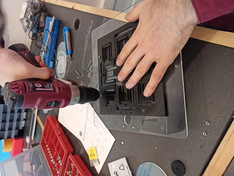
We re-designed the stage and several other parts in both SolidWorks and Fusion360.
The stage
Most of this part has been done by Jason. He decided to redraw the Urumbu and optimize most of the design to mainly increase the range of motion, increase the rigidity and finally, decrease the size.

We decided to print the new design using PLA but ideally, it would be better to CNC it in Teflon or Polypropylene to reduce the friction.
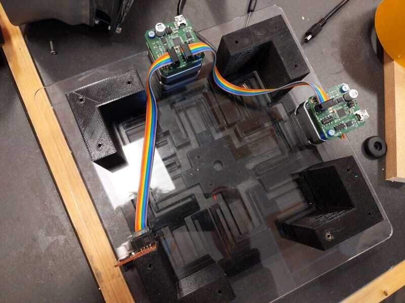
We also added a new stage for the motors and the new actuators.
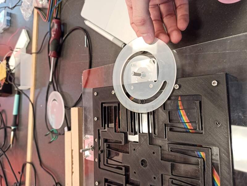
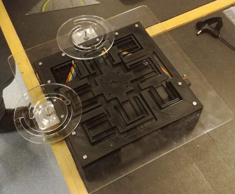
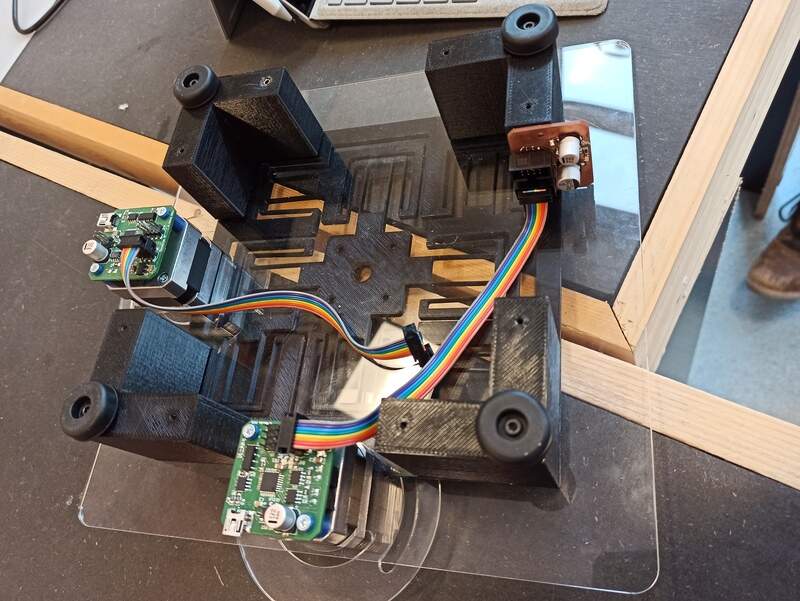
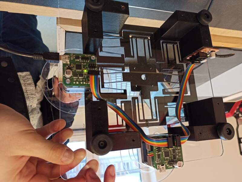
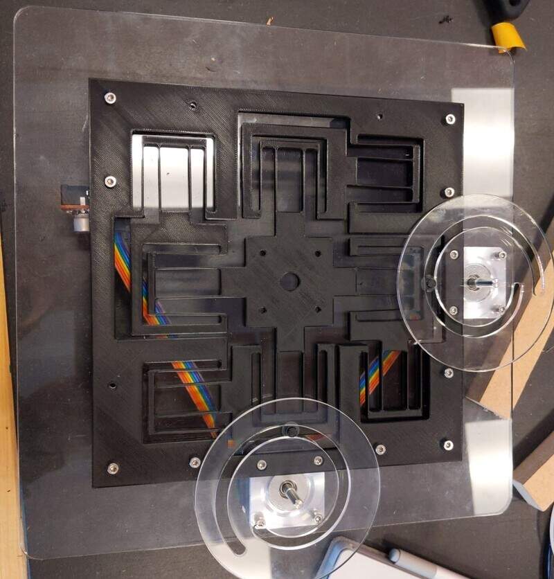
Here is what it looks like!

The motors are fixed on the side of the machine due to the spiral actuators (see below) and they are connected together using I²C.
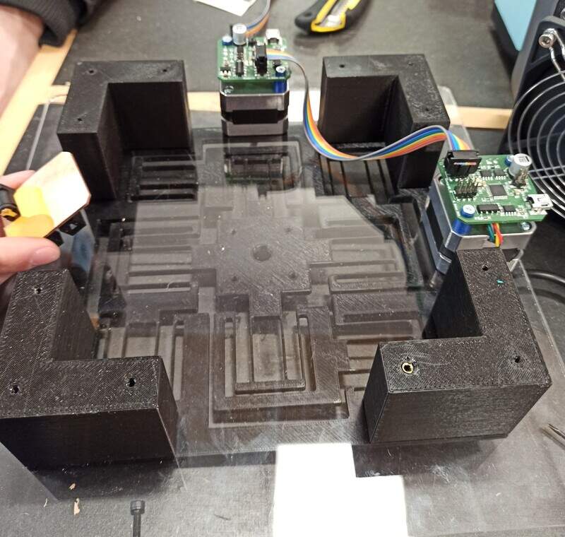
We initially took the wrong measurements so the motors were too high for our stage but with quick thinking, we were able to add some parts to raise our stage higher.
The actuators
The Urumbu machine was already more or less working but it lacked actuators. Quentin Bolsee added some motors last year but they were not working as easily as intended and they only made use of a quarter of the full range of motion.
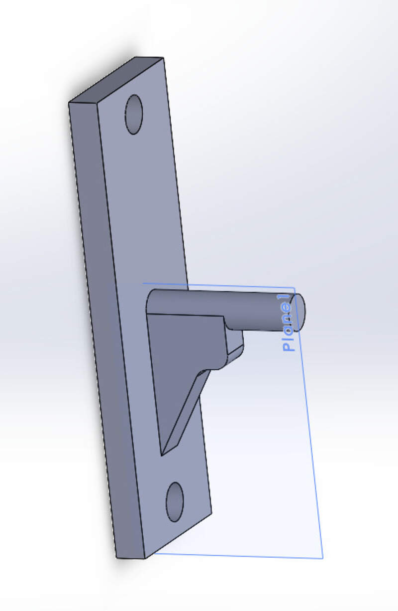
I decided to design new actuators based on a spiral shape. The idea of this design is to have actuators that are really easy and fast to make (laser cut or 3D-printed), have a high resolution and do not require specific material. Moreover, this kind of design does not need a lot of room. To be ideal, the spirals should be made of Teflon and bearings should be added (which we did) but they are not necessary for the machine to work.
The initial idea was to directly place the spiral on top of the motor:
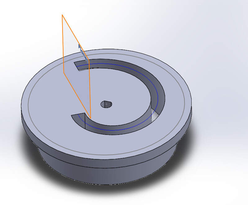
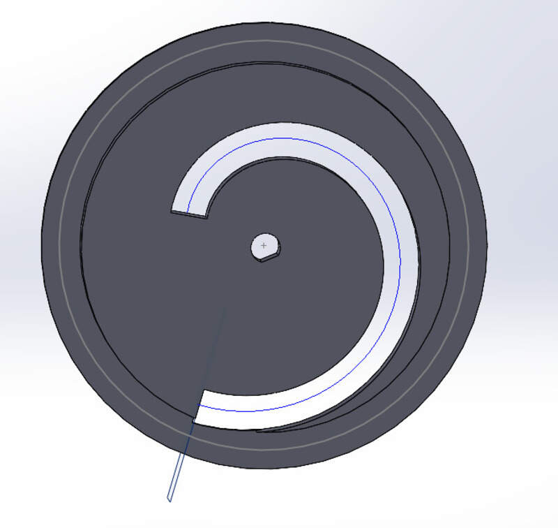
The idea is to obtain this kind of movement:
However, I then realized that 3D-printing takes quite some time and also, it would reduce the friction if we use laser-cut plexiglas.
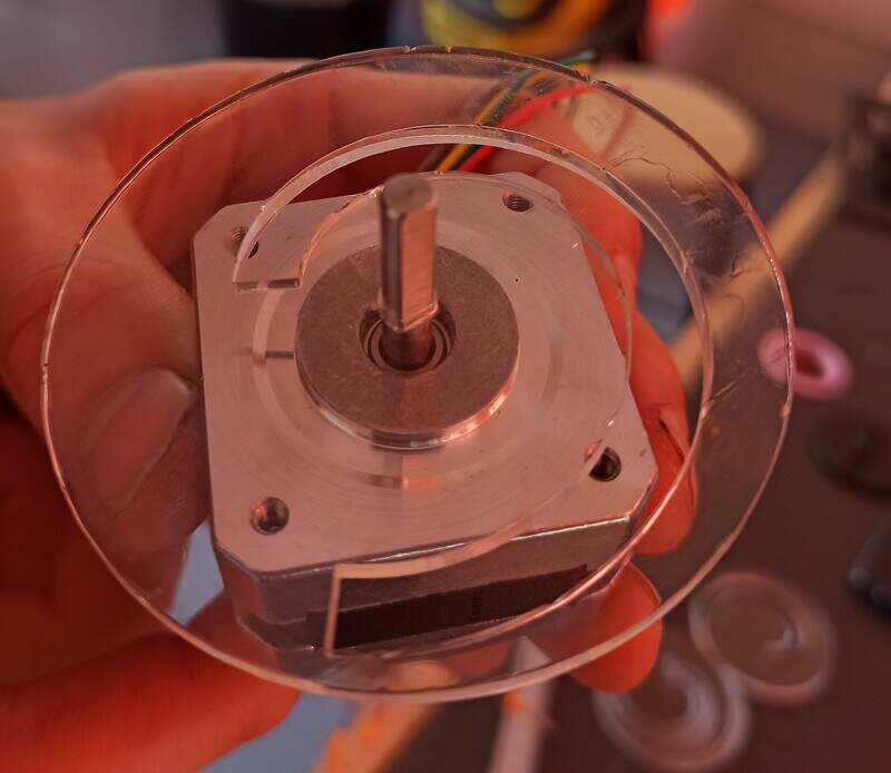
This early design was just a test (spiral management  ) but we ended keeping the same idea.
One other advantage of the spiral design is that even though you are limited by the size of the pin that will insert into the spiral, you can add many revolutions, and the more revolutions there are, the smaller the displacement resolution is.
We made several tests and in the end, to conserve some rigidity with the plexiglass and for this first version, we decided to use only a single revolution. Since we use stepper motors with 200 steps (see below) the resolution is still quite enough.
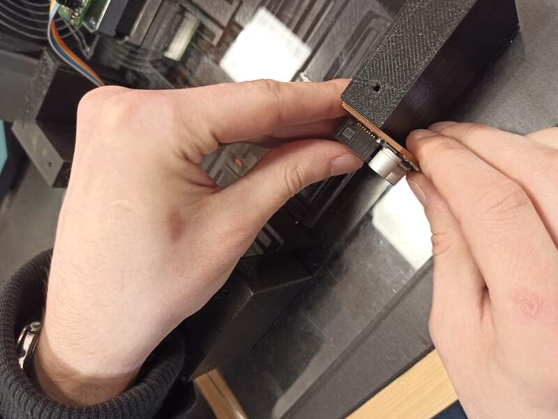
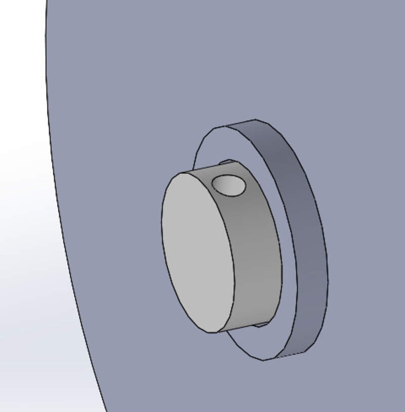
We used Teflon bearings to reduce the friction between the 3D-printed pin of the flexure design and the plexiglass.
because the spiral has to be centered initially, we had to offset the motor position on the stage.
As it can be seen in the video, the spiral design is not very big, very simple and easy to make and assemble, has a nice resolution, features low backlash, and are easily changeable to increase or reduce the resolution (number of revolutions, materials, …).
Another mirrored spiral could be added on top to reduce the torsion and improve the rigidity of the mechanism. We did not find it necessary but it might be a way to improve the system response and increase the number of revolutions (and thus the resolution) without losing too much rigidity.
Final design
The resolution is not very impressive :Nema17 stepper motors have 200 steps per turn, and one spiral turn is 3mm in the radial direction, so that makes a resolution of 3/200 = 0.015mm, not accounting for backlash and small errors. This can be increased through micro-stepping and by making more spiral turns with less radial distance between each turn.
Electronics design
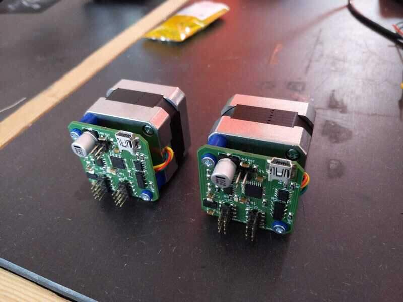
To actuate our machine, we needed some motors and some control.
We decided to use Nema-17 stepper motors and Quentin’s recent motor control boards. These were still in development so we spent some time troubleshooting them but, spoiler alert, it worked in the end.
Communication
The way it works is pretty simple. The idea is to have several nodes, all identical that can be linked together. The first node will be the one the USB is connected to so we can send some orders to the motors. We used the I²C communication protocol. In this protocol, we have one master and several slaves (in practice there can be multiple masters as well but not in our case). Each node can sense (using pull-down resistors) whether a node is following or preceding it. Using this information, we can easily deduce the master as the node not being preceded (except by the alimentation board but it does not pull down this pin). Then, each following node receives the current address offset, sets its address based on this value, and forwards the message to the next node with an incremented address. Once there is no node behind, the last node knows it is the last in the chain.
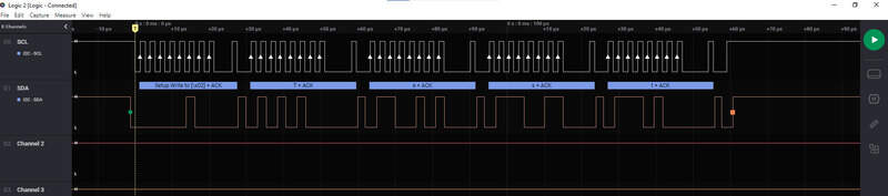
To communicate orders, we use the classical I²C, meaning we have a data and a clock lines. The clock is set by the master.
The master receives some orders through the Serial communication (either directly through a terminal or a Python script). If the orders are for him, then he does them, otherwise, he will broadcast the message over I²C (address first, followed by the message). The receiving node will then be able to acknowledge the message and reply if necessary.
Several orders can be defined using this syntax that we developed.
address:port=value
First, we specify the address (i.e. the node) that we want to talk to. Then, we specify the port, i.e. the value that we want to set for this node. For the moment, this can be either 0 for the position and 1 for the movement speed. Finally, we specify the value.
For example:
1:1=200Will set the speed of the second node to 200steps/second.0:0=100Will ask the first node (the master) to move to the position equal to a hundred steps from its initial position.
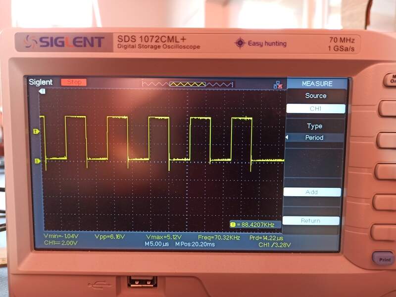
The I²C communication protocol can be seen on the oscilloscope and has been tested up to 30cm of wire length, at 100kHz:

All of the code is available in the design files but here is a snippet of it for fun, and as you can see, this not quantum mechanics
1 2 3 4 5 6 7 8 9 10 11 12 13 14 15 16 17 18 19 20 21 22 23 24 25 26 27 28 29 30 31 32 33 34 35 36 37 38 39 40 41 42 43 44 45 46 47 48 49 50 51 52 53 54 55 56 57 58 59 60 61 62 63 64 65 66 67 68 69 70 71 72 73 74 75 76 77 78 79 80 81 82 83 84 85 86 87 88 89 90 91 92 93 94 95 96 97 98 99 100 101 102 103 104 105 106 107 108 109 110 111 112 113 114 115 116 117 118 119 120 121 122 123 124 125 126 127 128 129 130 131 132 133 134 135 136 137 138 139 140 141 142 143 144 145 146 147 148 149 150 | |
Additionally, for later developments and complex shapes, it will be required to handle the synchronicity of the movements. We can therefore implement it as a “sync” message that is broadcasted (no address) over the I²C network.
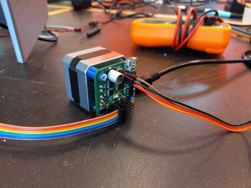
Motors and supply
The motors are 12V Nema-17 stepper motors. We need a board that will be able to supply and regulate this voltage. The supply board can be fixed onto the stage and the motors are screwed directly on the stage on the side.
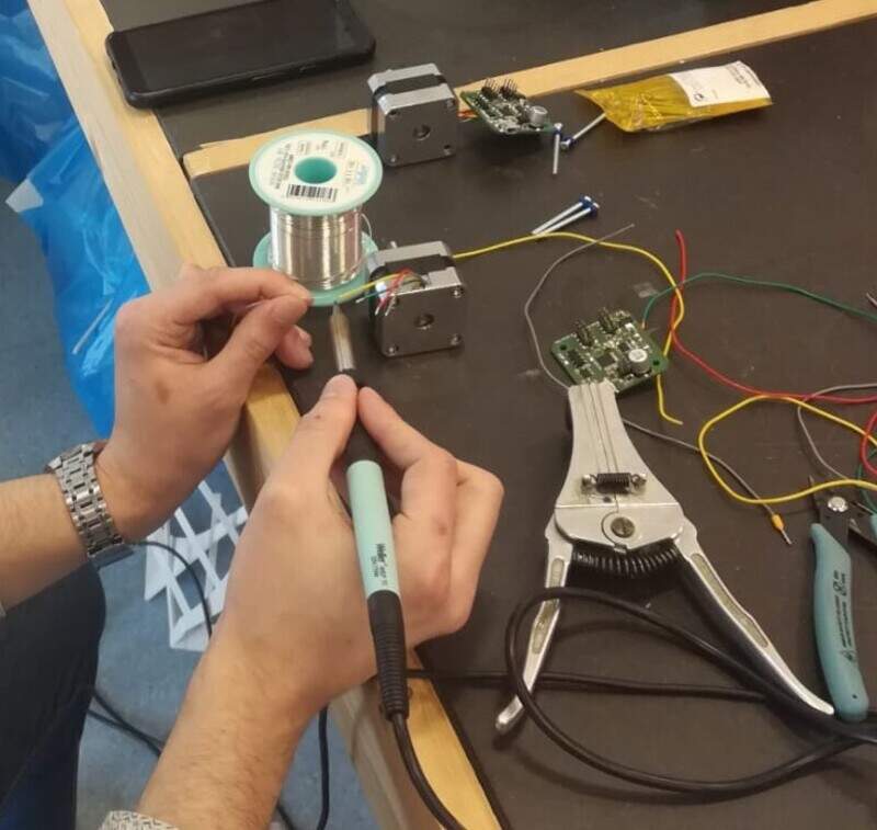
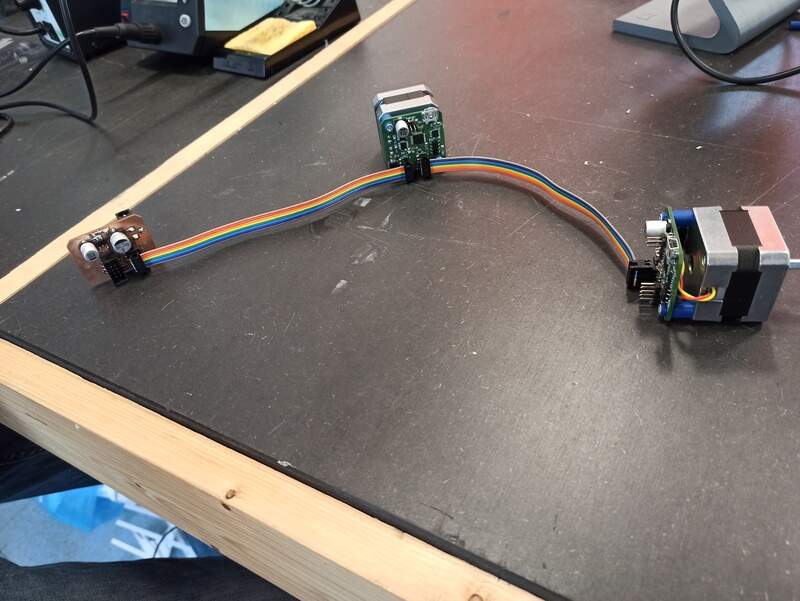
Then, we had to connect the motors to the communication boards but first, let’s test the motors before assembling everything:
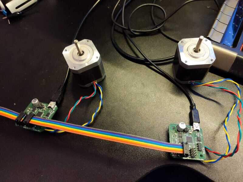
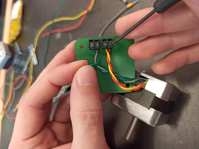
It works ! Let’s finish the assembly.
End result:
In the end, using a Python code that sends the data over Serial, it was really easy to make a square shape.
1 2 3 4 5 6 7 8 9 10 11 12 13 14 15 | |
Issues
We had issues with the solidity of the spiral, we broke one or two before making it work and we also had with friction due to the “bad” surface state of the initial design of the spiral.
To solve that second issue we moved to laser cut PMMA and a teflon ring to minimize friction and that did the trick !
Further improvements
Future developments can focus on 2 aspects :
- Stiffer material : Water jet cutting metal to have a stiffer the durable flexure, this will require some simulation to avoid wasted material. The mechanical stage could be CNC’ed in Teflon to limit the stress on the PLA, which would probably reduce the fatigue wear on the design.
- Z-Axis : The machine currently lacks a Z-axis which would be necessary to make it a full cnc machine be it a pen plotter or something else.
- Finer motion control : the spiral idea is interesting but does not allow for very fine movement so another design should be made to improve that. Maybe, the spiral idea could be further researched to increase the resolution and reduce the backlash.
- Micro-stepping could probably be added to the motors to further increase the resolution of the motion
Automatic window shutter
As Spring is finally coming around, the sun starts hiding our screens at the end of the day when the sun sets. Because of this, we also decided to design a machine in a single day that would be a prototype to avoid this kind of issue.
The idea is really simple: having a shutter that moves with a motor, some fishing lines, a pulley, and a pair of photoresistors to detect whether the light is present or not.
Mechanical design
We need only a few things:
- A motor case.
- A pulley system
- Some wires or fishing lines
- A capstan to wrap these wires
- Some cardboard to make our testing window prototype
Using SolidWorks I designed these parts, making sure they were all designed parametrically so that changes could happen very fast if we needed to iterate!
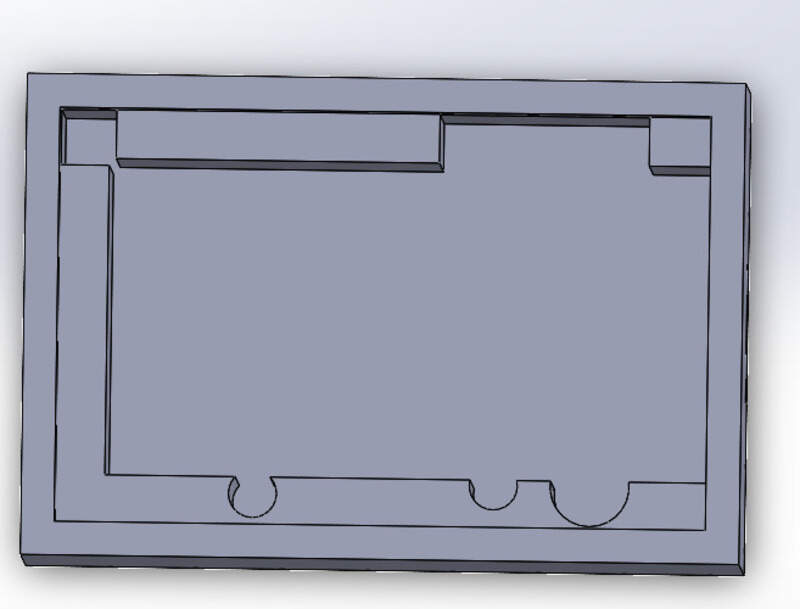
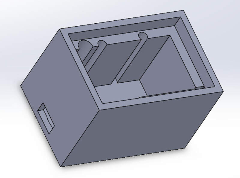
The motor case:
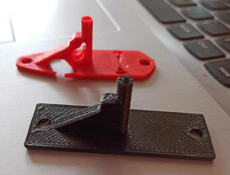
The DC motor we found was not flat, mainly because it also features a gearbox (Oops forgot to take a pic…). So we needed to make it flat so that it is just easier to manipulate and place in our design. Nothing too difficult, here is the result
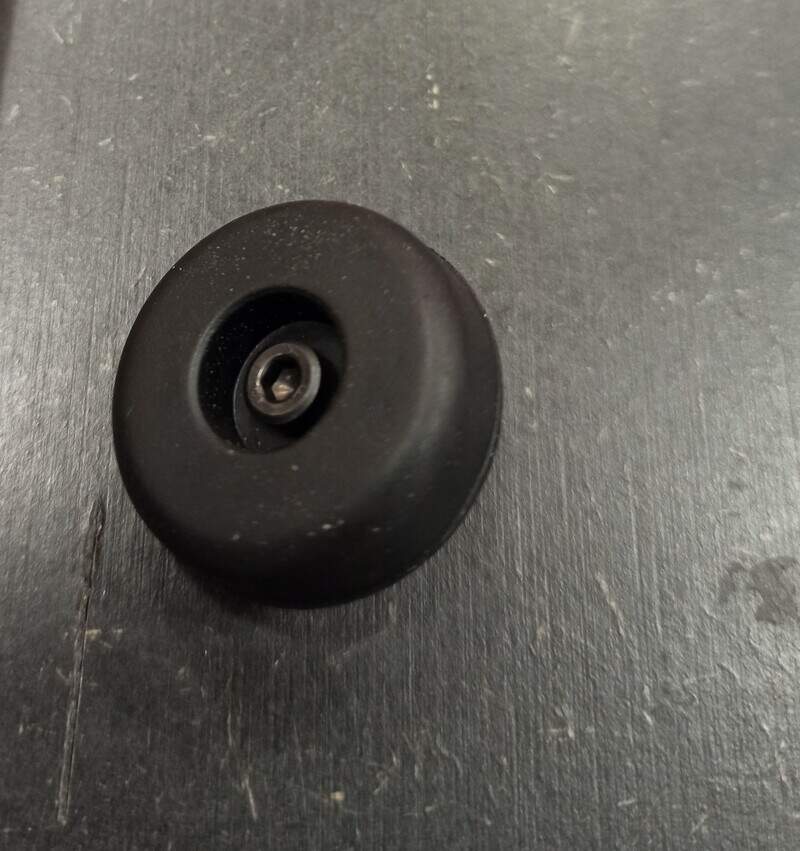
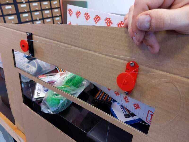
Pulley system
We need a “circle” with a narrow band to hold the wire in place. This circle must be able to rotate freely on an axis that will be placed horizontally.
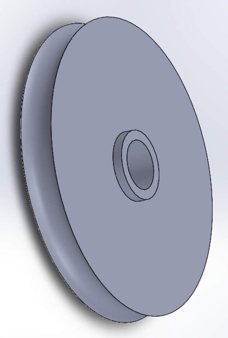
With this design, the wheel can turn freely while being held in place, exactly like we want.
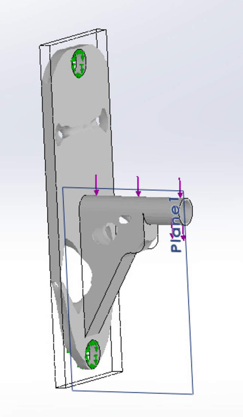
Then I wanted to test the topology optimization. I made some stress-strain simulations in SolidWorks and made a new topology study to try to remove as much material as possible while minimizing the impact on the deformations.
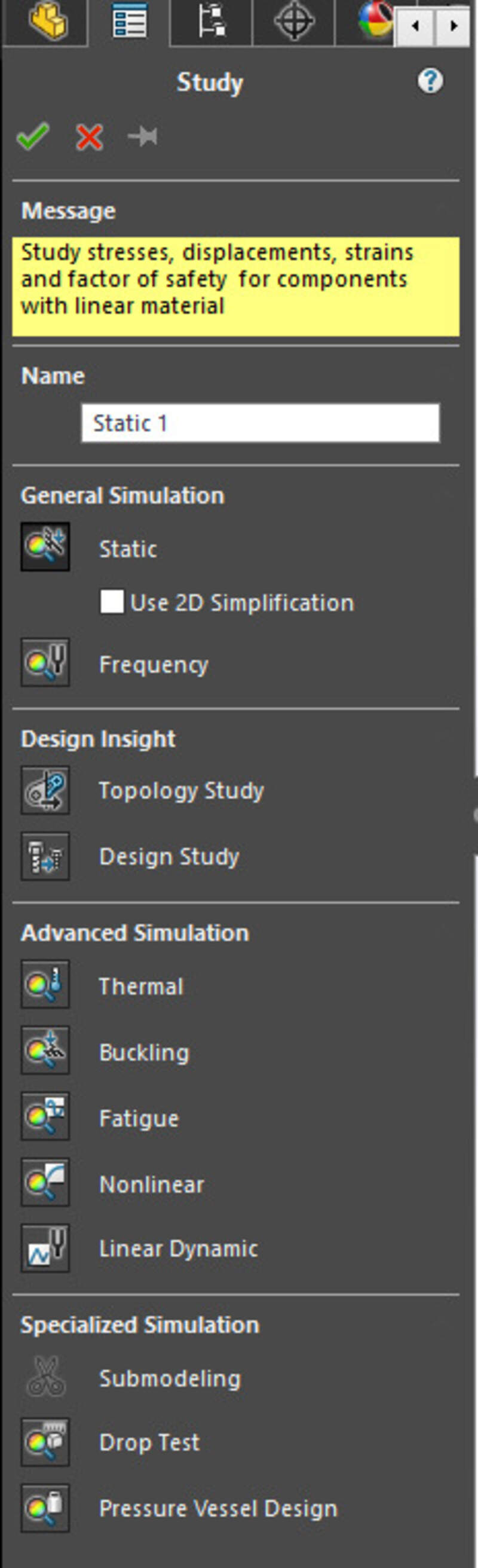
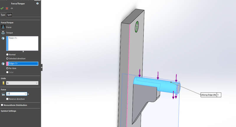
I then needed to define the material (I chose ABS but we used PLA instead, it did not impact our design much), the fixtures (i.e. the parts that are fixed in the design), and the external load (I estimated a safety margin of 2kg of force in the vertical direction).
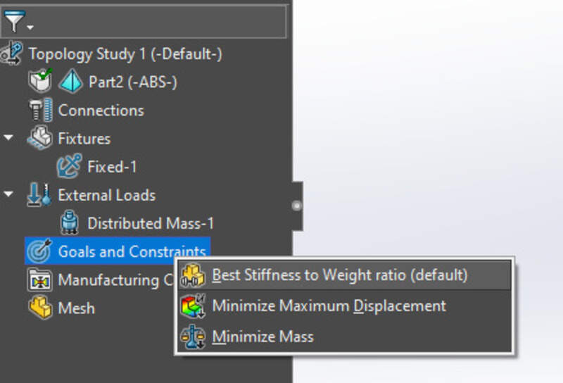
Finally, you can set the goal of the simulation: here, obtaining the best stiffness to weight ratio.
Time to run the study:

And observe the results
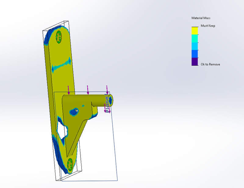
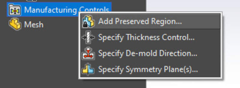
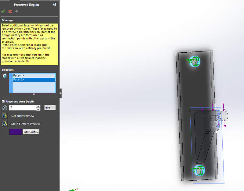
In this case, I was not really happy with how much material was left near the screw holes… Let’s try again but this time while specifying that we want to keep some material there.
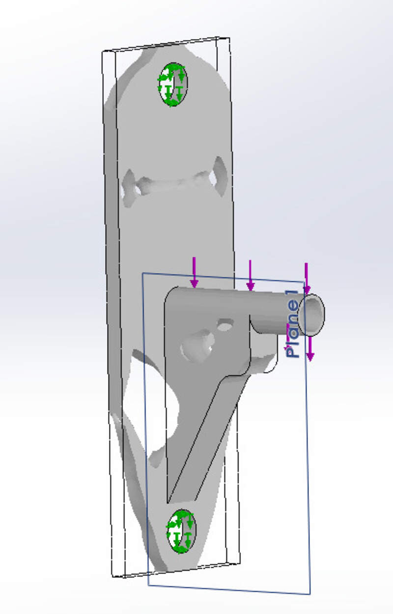
This time, we are much more happy ! In the end, it held the load extremely well, while having a similar printing time (31min VS 29 min) but material quantity being reduced (0.9m of PLA filament VS 1.25m) !
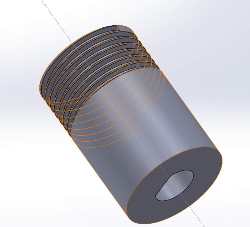
Capstan
To wrap the wire (or rather the fishing lines that we used), I made a capstan really easily in SolidWorks using the revolution, helixes, and linear patterns functions. Why the capstan you may ask? Well, the critical influence of friction on this kind of device emphasizes the importance of how the motion is transmitted along the system. The selected design is a pulley-capstan system because this reduction technique introduces negligible friction forces in comparison to traditional gearboxes, avoids backlash, and provides a reduction efficiency of nearly 100%. I chose of V-thread instead of a smooth capstan to have two contact points between the cross-section of the cable and the thread which increases adhesion. To avoid slipping, we can do multiple turns and we know that wrap friction increases exponentially with the wrapping angle. 3 turns should be enough. Finally, it will prevent the cable to wrap around itself and therefore will limit the change in response to a specific command as the diameter of the capstan will always stay the same.
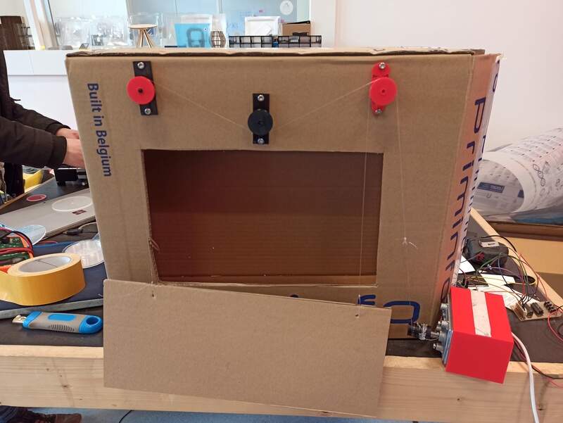
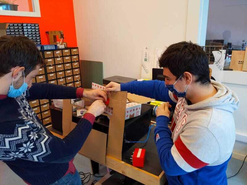
Assembly
We mounted everything on a cardboard box that was made to imitate the window in a room.
Electronics design
Motor control
To control the DC motor, I used a circuit that uses a 7404 (inverter IC) and an L293. the L293D is a Half-H driver, with the D version already features some diodes to protect the circuit from the high voltage when switching the motor off (the role of a flyback diode is especially to prevent this overvoltage by providing a return path for the current to discharge in the motor inductor resistance, otherwise V = Ldi/dt… and boom!).
Here is a simple schematic that explains it.
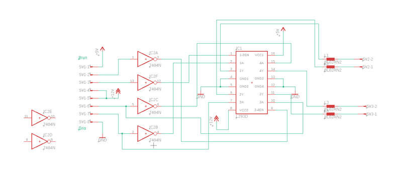
I have multiple wires at the end of the board: I can control two motors, meaning I have 4 outputs (two per motor). The grey wire is the GND. Yellow and green = +12V motor supply. Orange and red = Enable (motor turning) (active low) Purple and blue = Direction of the motors. Brown = logical high (5V).
To have an easy time, I used an Arduino Due to control the motor (two digital pins for the direction and the enable) as well as the 3.3V, 5V and 12V from the Vin pin (I supplied the Arduino using a 12V DC Jack).
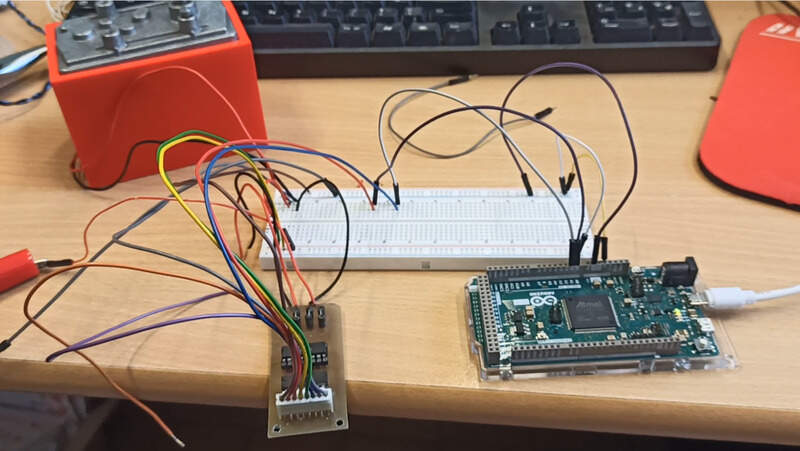
With everything connected, it was really easy to get the motor to turn in both ways.
We can then simply hook it to the mechanical design to get a moving shutter
Light information
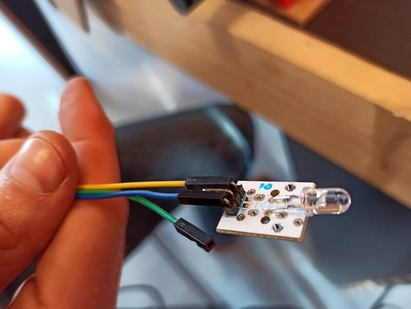
To get the information about the lighting, we used some phototransistors. Jason did the schematic but all in all, it is quite easy: we have two pull-down resistors and a 3.3V source. The phototransistor lets the current flow more or less depending on the amount of light received so the value of the voltage just above the resistors varies depending on the amount of light!
we can then fix this little PCB inside our “cardboard box” and start experimenting:
As we approach an infrared LED, we can observe that the voltage increases:
We can also observe the voltage variation as we are near the window and the “shutter” moves around
As the shutter is raised or lower, the amount of light changes.
End result
In the end, it was snowing the day we built it so… We were not really able to showcase its ability but we were able to:
a. Detect the amount of light received (though it was really difficult as the weather was horrible and our photoresistor was not reactive to the LED light of our phones which was all we had).
b. Move the shutter using the motor according to the amount of light perceived by each phototransistor.
Possible improvements
This is a very simple proof of concept. This idea should be realized in a much bigger scenario, i.e. to cover a real window. Also, the phototransistor used are a bit too close to one another so spreading them further apart would make the blinder more responsive. The pulley system is very simple and would beneficiate from an increased pulley to hold the cables very tight and to make the channels in the pulley a bit wider and deeper. Finally, the motor we used a very simple DC motor but using servos or simply stepper motors would make the control much more simple, rather than having to rely on H-bridges and an L293D.