6. Electronics Design
Group assignment : Testing some circuits with lab equipment
SAMD21 and Logic Analyzer
For the group assignment, we had a look at our instructor Quentin’s new circuit which is using a SAMD21E18. This little chip is able to act as any device including keyboard, MIDI, serial device and so on…
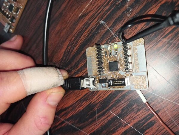
Also, it can be directly programmed using Python which is extremely nice and is able to communicate (using the Python’s libraries) using SPI, UART, I2C and others.
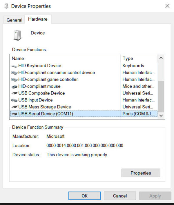
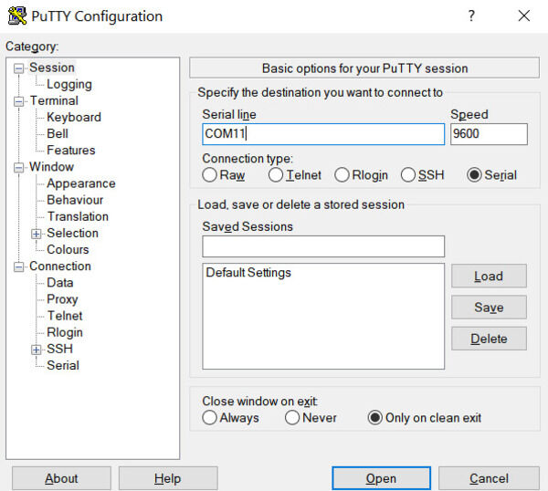
Since we’ve seen that the µ-C is available on COM11, let’s try to communicate with it using Putty, a terminal emulator !
Once the communication is established, the code resets, runs and finally finishes. On the board, we see a LED blinking 10 times.
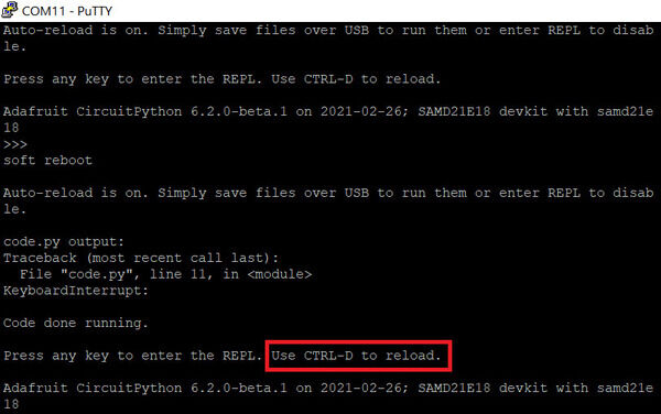
Opening the “code.py” file we can see the following code that runs in the µ-C:
1 2 3 4 5 6 7 8 9 10 11 12 13 | |
This code basically sets the PWM duty cycle of the pin controlling the LED to a continuously increasing and decreasing value, for 10 cycles.
By adding the print statements, we were able to also monitor the code run in the terminal !
We then tried to use the Python interpreter inside the µ-C to play with the LED.
First, we familiarized ourselves with the library used:
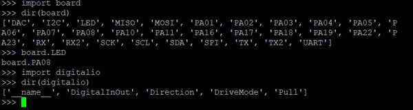
We can see that the “board” module contains all the available pins, some are named by their functions “LED”, “I2C”, “SDA”, … We can also see that the board.LED pin is in fact the pin 8 (or board.PA08). By importing the “digitalio” module we can see that we can program the pin to be either input or output and the digital value of it as well as its pull-up.
Let’s try to light the LED using the Python interpreter:
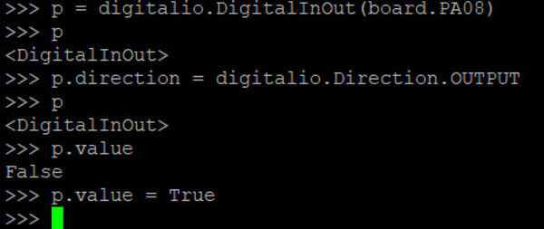
It works (oops, forgot to take a pic !). Let’s make our own code to blink the LED and see the result :
Great ! Now that we visually see that it works, let’s try to measure it using other tools.
The Saleae Logic 8 analyzer
Blinking LED : PWM
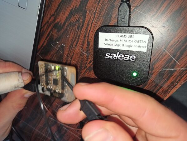
I recently bought a Saleae LA for the Uni but didn’t have time to test it. Now is the perfect time ! We connect the mini-probe to both the ground and to our pin and plug the LA via USB to the computer.
Using the Logic 2 software we can start recording ! The nice thing is that the LA can record both the digital (upper row) and the analog signals (lower row). We can therefore have a look at the shape of the signal and detect any interference or issues with the signal itself.
Let’s try to change the output of the pin:
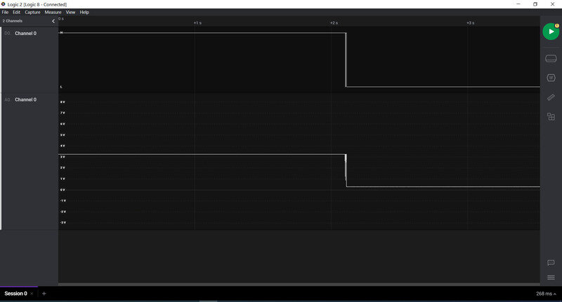
Now let’s run our blinking code:
On this large scale we clearly see something.. But what is it ? First, we need to understand that we just like before, we are modulating the duty cycle of the PWM signal. Basically that means that we go from a 0% high time/low time to a 100%.
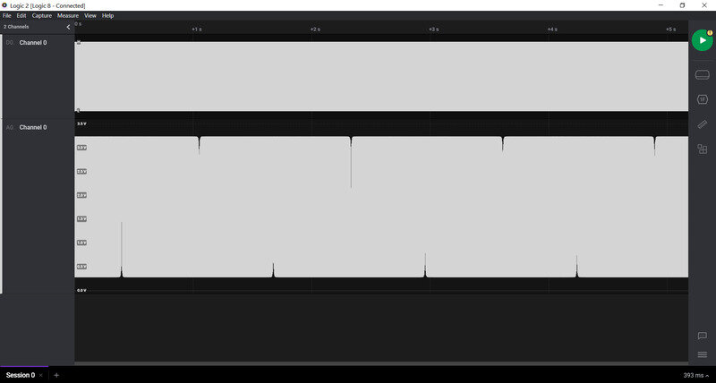
Let’s zoom in:
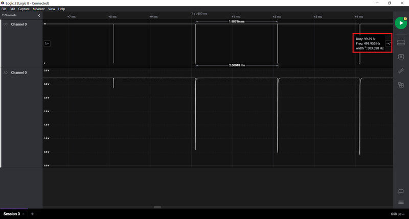
We see some spikes ! Actually they are the PWM signals with a very low duty cycle (i.e. close to 0%). Whenever we reach the lowest point, the voltage isn’t even able to reach the “high” state.
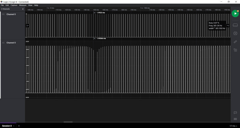
Zooming even more:
Here we clearly see that the spikes are actually very low duty cycle PWM.
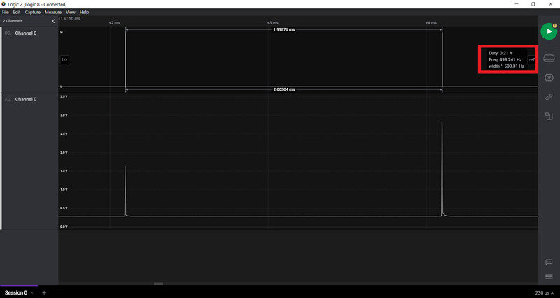
Let’s have a look at the “high duty cycle” part of the signal:
Here similarly, the voltage cannot reach the low state at high duty cycle.
Finally, let’s look at the signal in the middle
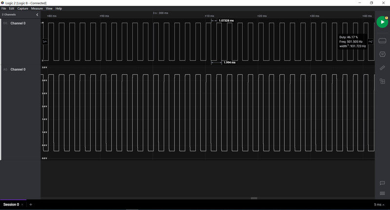
Just like we expected, we here see a very nice PWM cycle.
Communication protocol
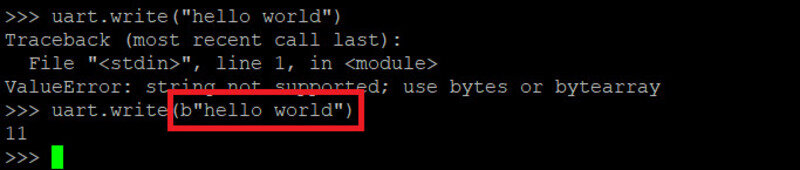
We then tried to observe the signal that happens when communication occurs. First, we tried to enable the I2C protocol but it requires pull-up resistors on the SDA and SCL lines which we didn’t have. We then tried the UART protocol but couldn’t make it work for whatever reason (maybe the RX pin was not pulled down correctly ?). But when we tried to communicate we noticed we needed to explicitly send the message as bytes using the “b” flag.

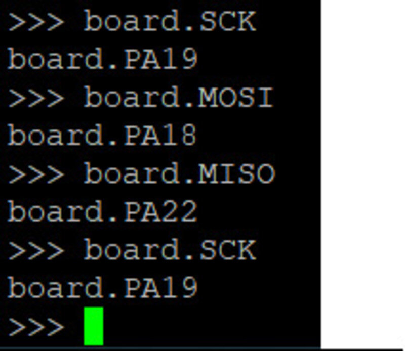
Finally, we tried the SPI which needs 4 lines (MOSI, MISO, CLK and SS/Enable). We found the corresponding pins:
And we “locked” the communication to be able to write the message:
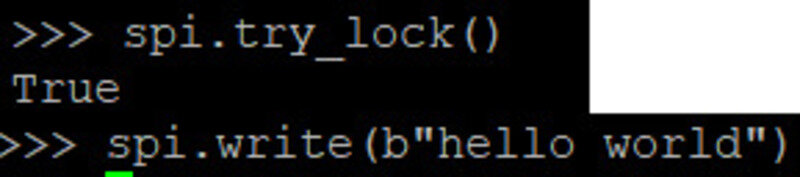
Let’s analyze it in Logic 2:
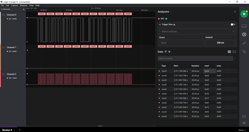
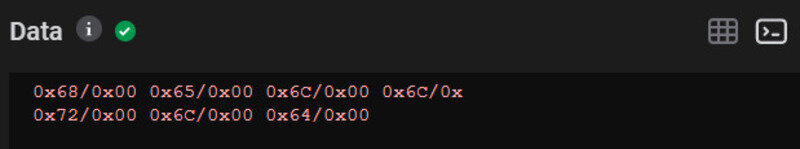
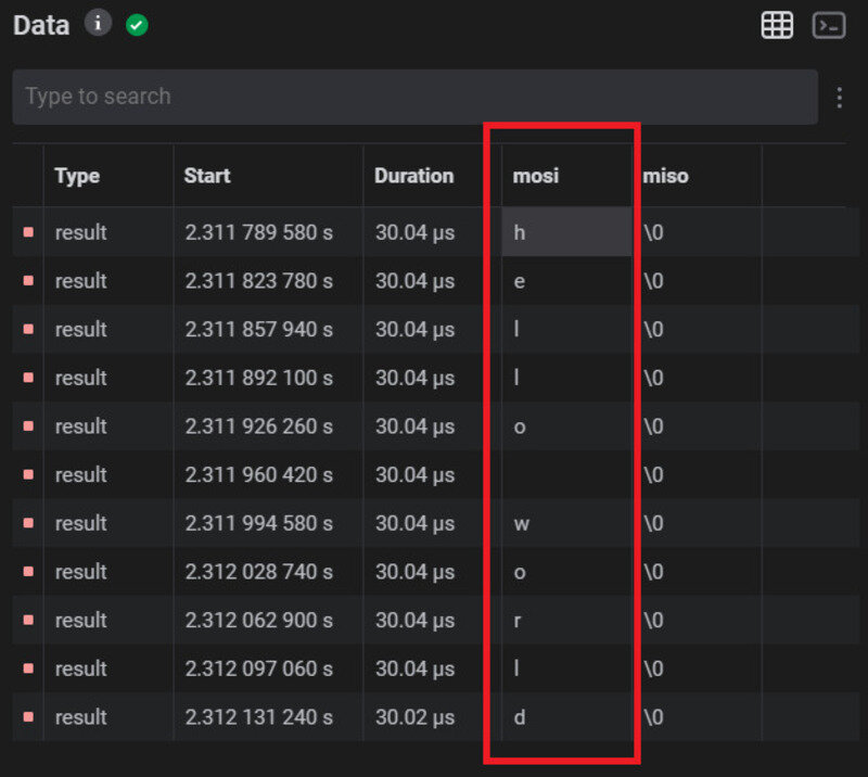
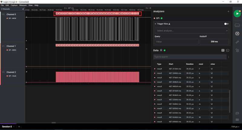
Now the problem is that the message appears in hexadecimal, let’s change the encoding!
We can now try to send a different message! What about “Hello to the FabAcademy world!” ?
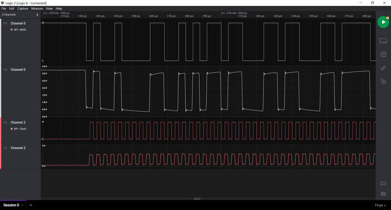
And let’s have a closer look at the shape of the analog signal
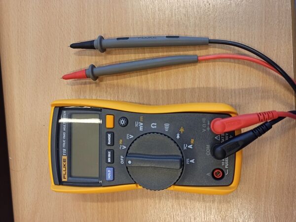
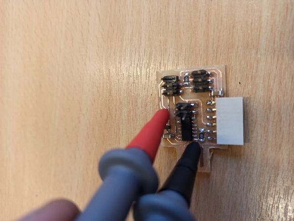
Multimeter
At Uni we also have a Fluke 115 multimeter. The best use for it is to check for continuity to detect defect tracks that are either short-circuited or open-circuit (and shouldn’t be). It can also be used to check the value of resistors or the direction of a diode.
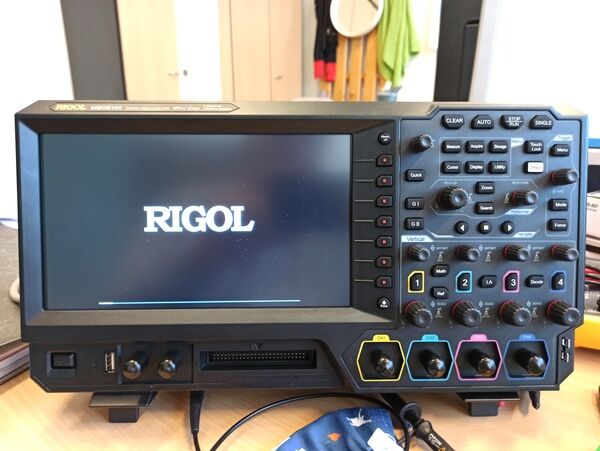
Oscilloscope
We also used a MSO5104 oscilloscope to check the output signal of my previously designed PCB and the “analog” pins of an Arduino Nano and Arduino Due.
The Arduino Nano is unable to provide a real analog voltage as it lacks digital-to-analog converter. When using the command analogWrite(value) it actually outputs a PWM signal whose duty cycle is proportional to said value.
The Due however features a DAC and can output analog voltage.