12. Output Devices
Group assignment
Consumption measured using the power supply
For the group assignment, we measured the current consumption of an LED on my ESP32 board right here.
Because I was powering the board with 3.3V and the current consumption increased from 0.37 to 0.44mA when lighting up the diode, I can deduce the current consumption of the LED to be 7mA which gives a total heat dissipation of 23.1mW through the LED and the current limiting resistor of 220Ohms.
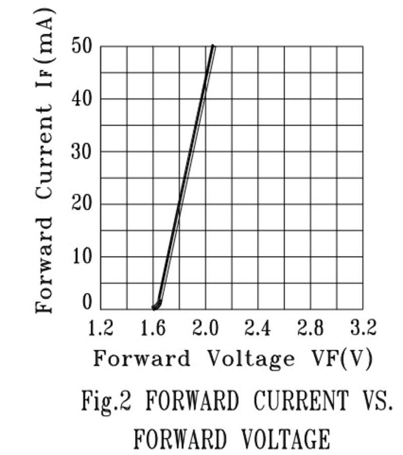
We can also compute it in another way. I have a current limiting resistor of 220Ohms and the LED has a forward voltage drop of 1.6V for 7mA. Powering from 3.3V, that leaves 1.7V through the resistor, which is indeed very close to 7mA.
Also, for another project, I powered another LED through inductive powering. I supply my class E amplifier with 9V DC and the current consumption is about 30mA (varies with the distance between the primary and the secondary of course). The power consumed is therefore about 270mW in the class E.
Using a shunt resistor
It also possible to use a very small value resistor (1 Ohm or less) to measure the current consumption. Indeed, the resistor must have a very small value to not affect the load and the correct behavior of the circuit.
It can be very useful to see the transient power consumption, for example when a µ-C is processing a lot of information,.. which is something that can happen very fast and therefore will not appear on the power supply information.
Consumption of an op-amp in buffer configuration
In fact, it is very interesting to see the difference between the theoretical circuit and the effects in practice. For example, wires have an non-negligible resistance value but also inductance value.
Inductances will oppose themselves to current variation and therefore, when we have a high current-consumer in the circuit, if it is located far away from the voltage source, charges will see a lot of inductance and will not be able to reach the consumer very quickly. Therefore, due to Ohm’s law, the voltage at the consumer pins will decrease.
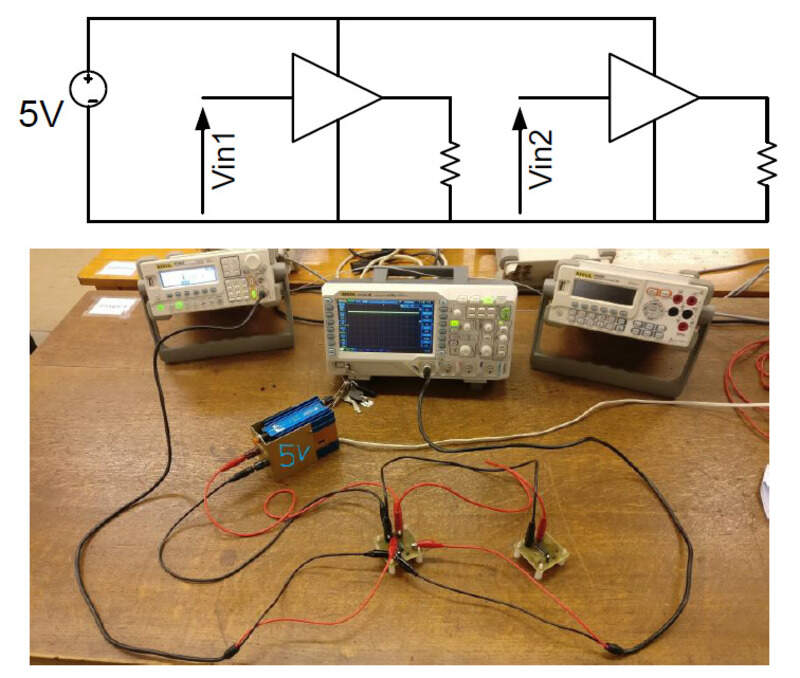
We can then compare the effect of wiring a circuit in “cascade” or in a “star” configuration.
The “cascade” configuration is the most intuitive one.
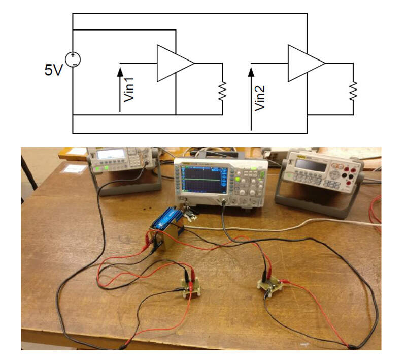
That star configuration is when every wire starts from the power supply.
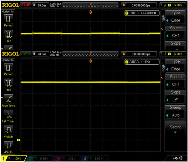
Let’s then input some high frequency (10kHz) square signal at the input of the buffer op-amp and let’s see the voltage at its pins but also at the pins on the second op-amp.
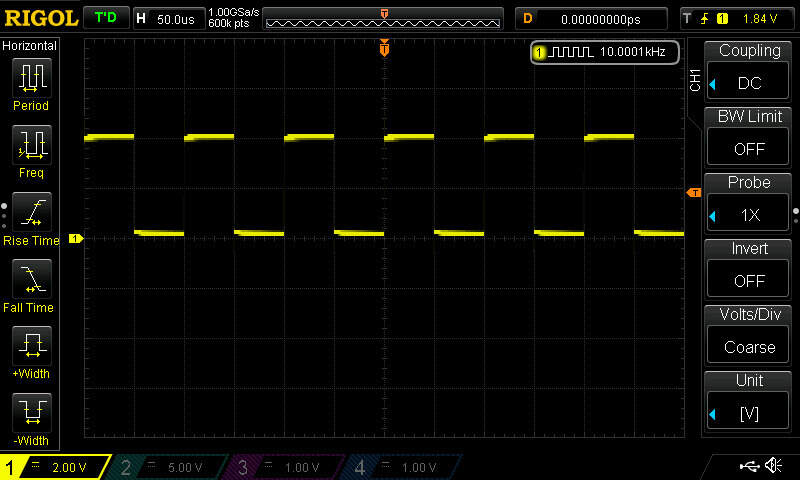
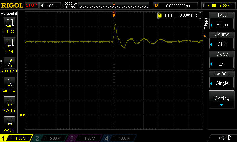
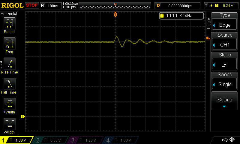
We can clearly see that the second op-amp is affected by the current consumed by the first. In a star configuration, the amount of wire in common is reduced and therefore, the second op-amp will be less impacted
This problem can be mostly solved using capacitors that will hold charges near the consumer op-amp and will be able to deliver them at a very fast rate since the inductance (the amount of wire) between the capacitor and the op-amp is very low.