4. Electronics Production : Machine setup and characterization
This week, we milled our first circuit board.
Follow us in this journey to learn how to do it.
| Illustrations | Description |
|---|---|
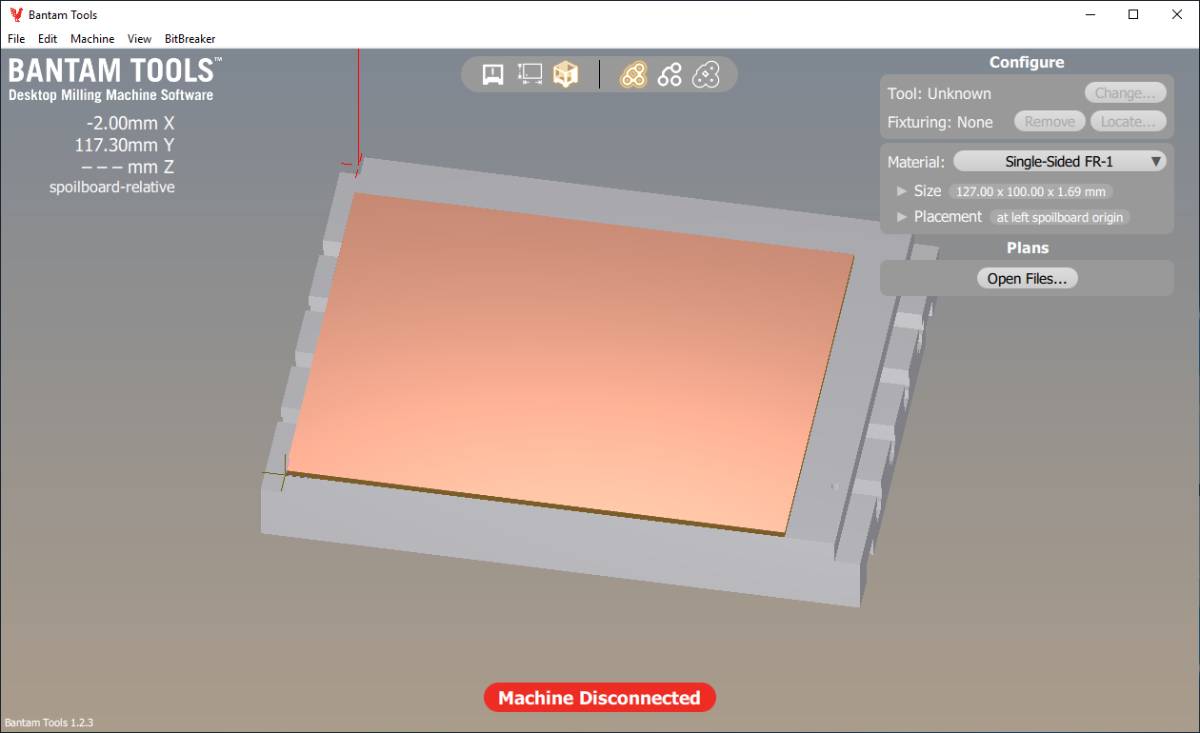 |
When we open BanTamTools we get this window |
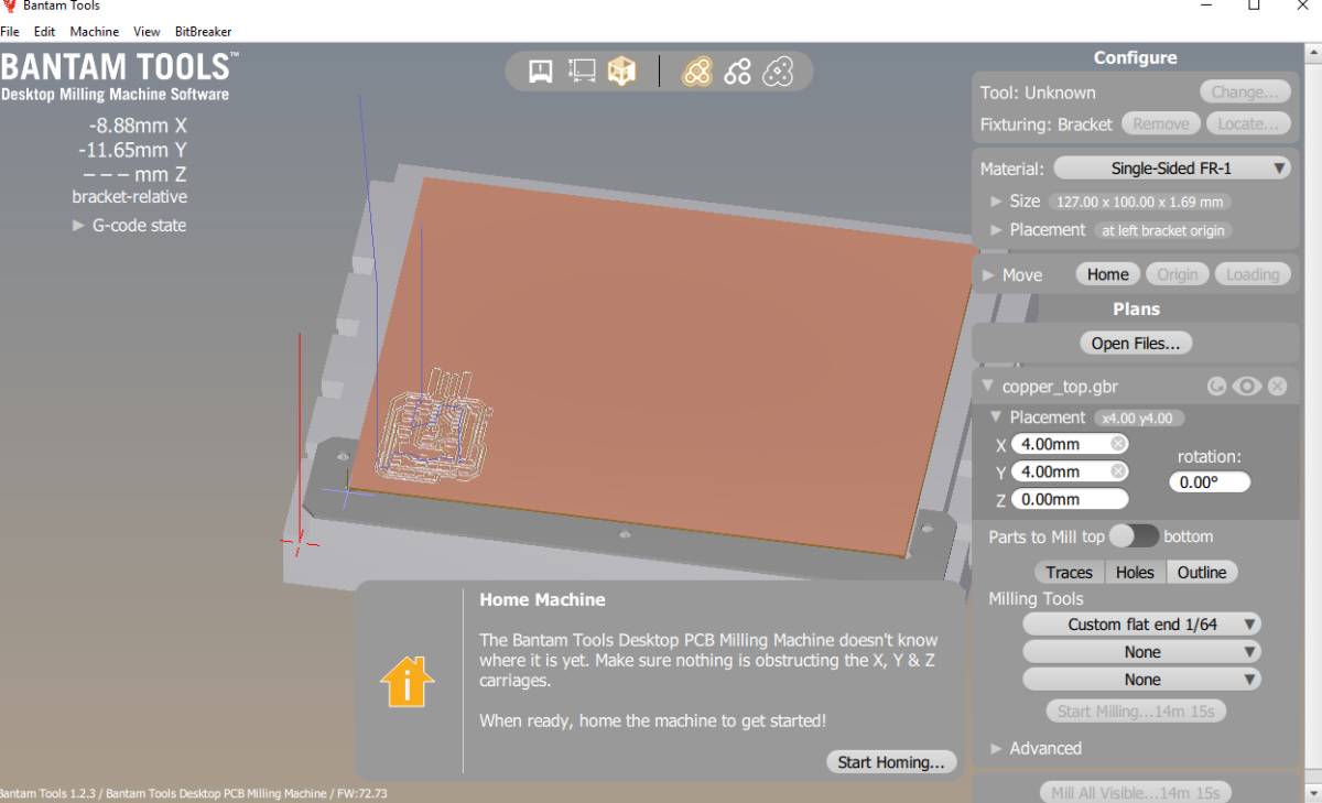 |
Because the machine uses stepper motors, it does not know its position so the first thing asked is to home it, which makes it reset its position |
 |
Homing |
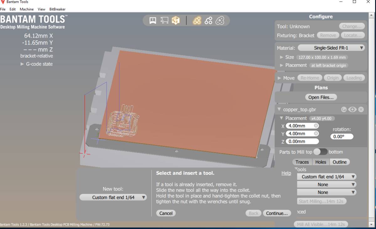 |
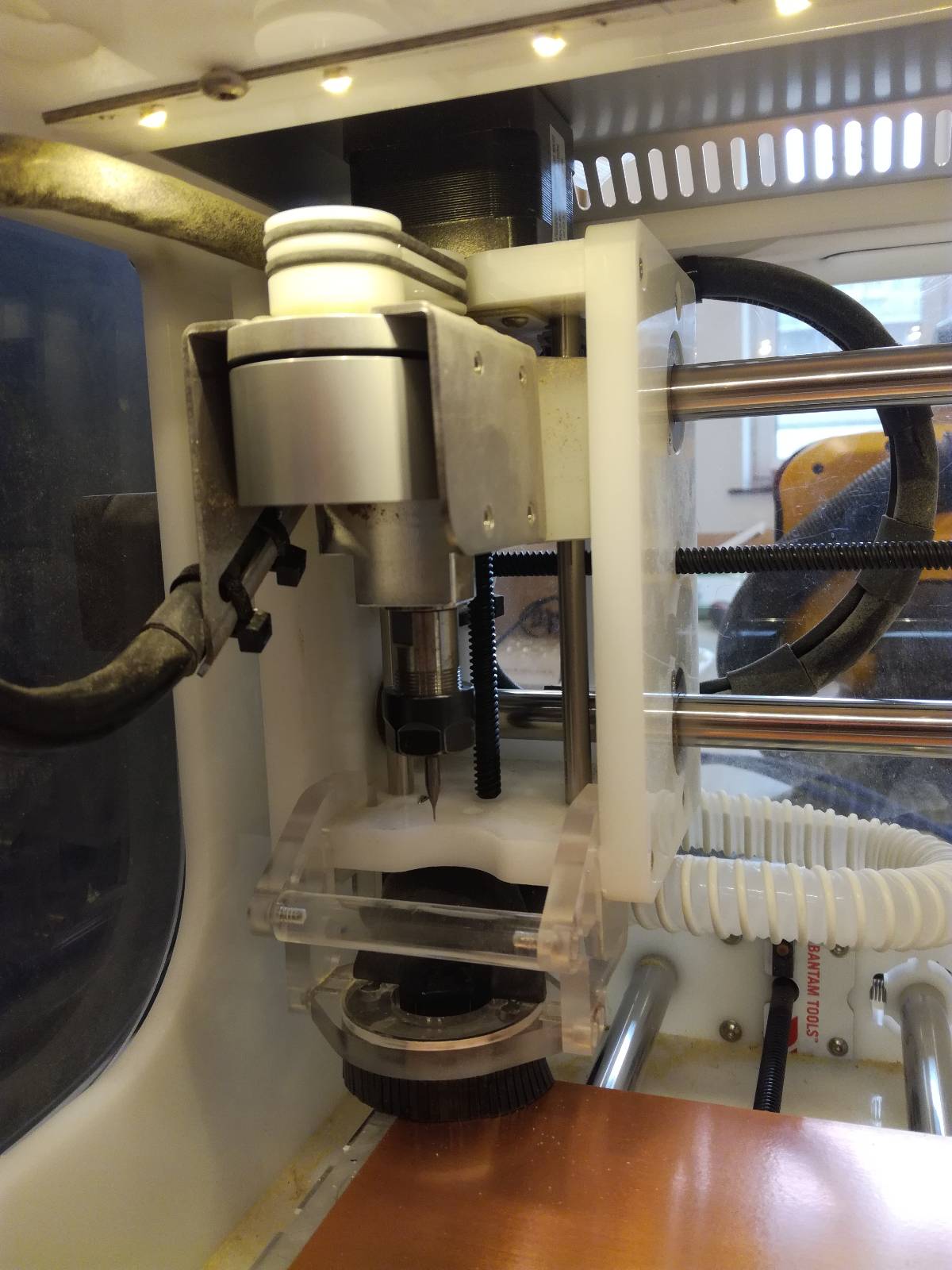
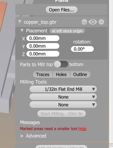
Then you should select a tool, in our case we’ll use the Custom 1/64 flat end |
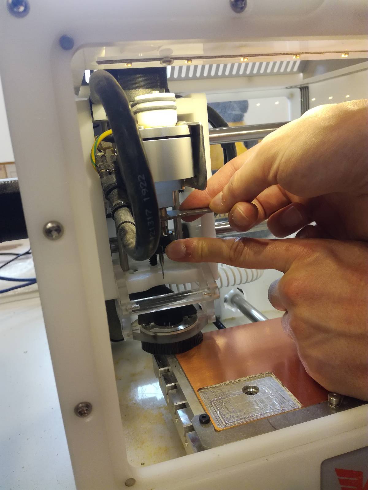 |
When changing the tool, we must be very careful not to drop it vertically otherwise it is very likely to break ! |
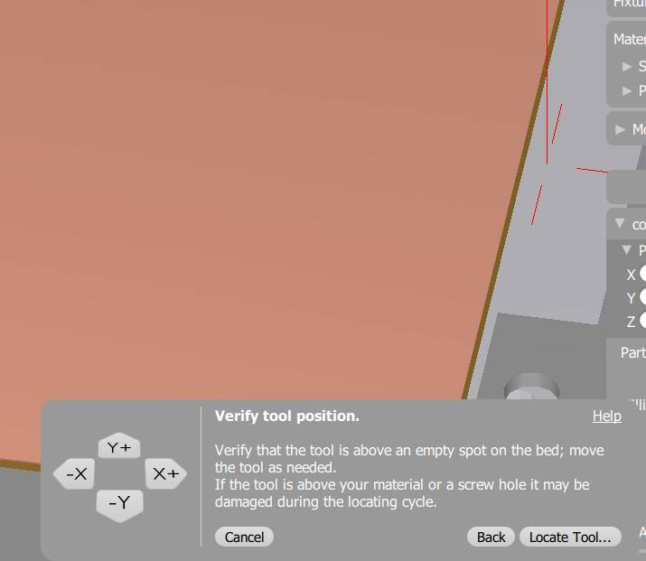 |
The tool does not know the vertical position of the tip of the milling cutter. To discover it will descend it very slowly on the side of the stage which height is known. Move the red cursor to a suitable position on the border as displayed in the image. |
 |
We still have to measure the thickness of the copper board. To do that we use the BitBreaker tool which has a good name, because if you don’t do it well, it breaks your milling tool. |
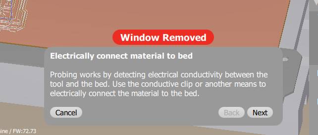 |
The detection of the tool is done by closing a electrical circuit passing by the milling tool and the copper plate. |
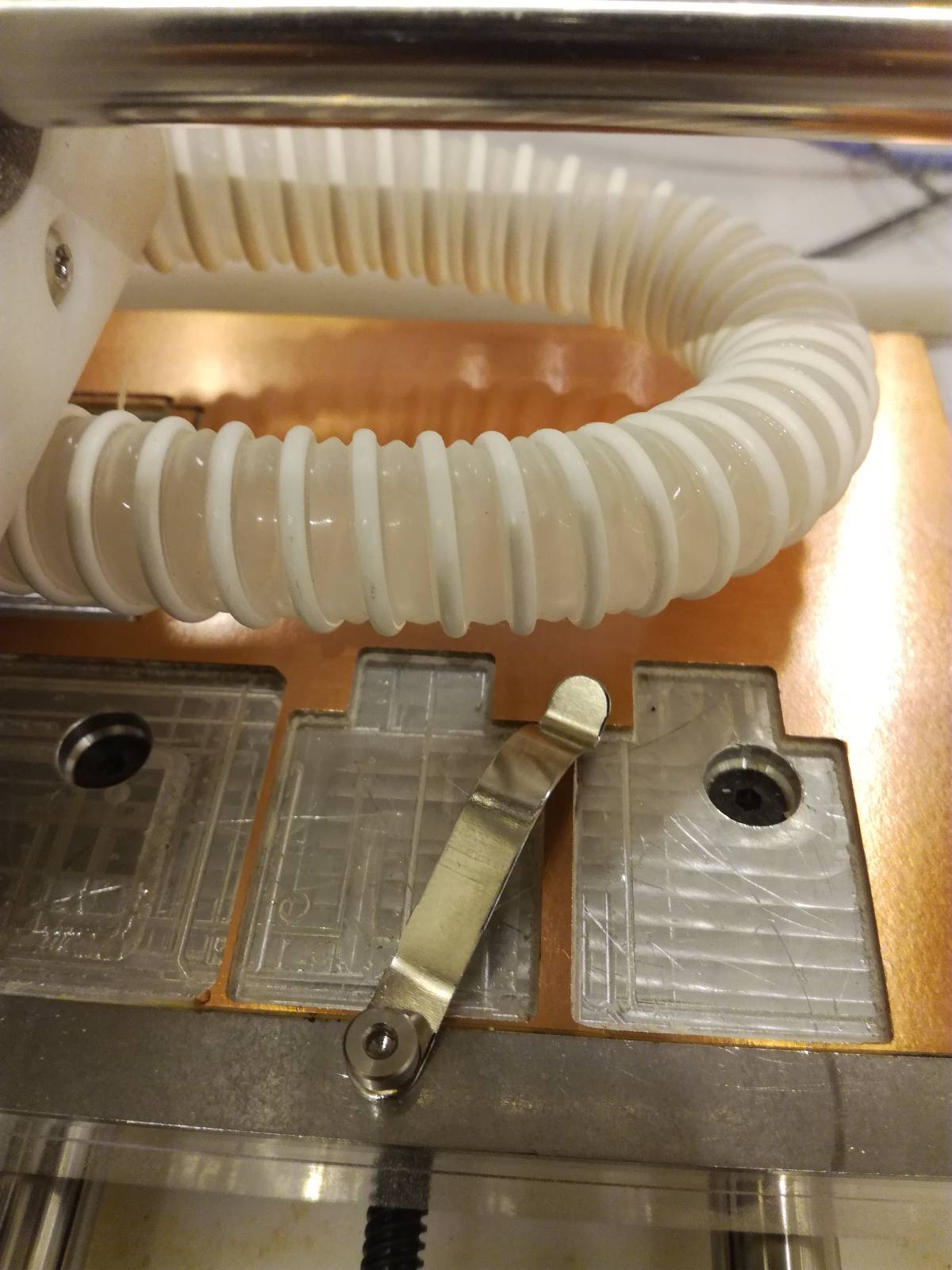 |
To close the circuit, you move the leg onto the board. |
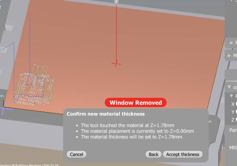 |
I have measured the board already and I know it is 1.69mm but what happens if I do the measurement in the center of the board rather than on the side. Well the result is very different, we get 0.08 mm in difference. This is not much but considering that our trace depth is 0.15 this is huge ! So always measure on the sides ! |
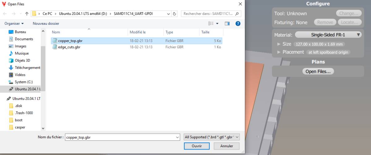 |
Once the machine is set up, we open a file. Here we’ll select Gerber files |
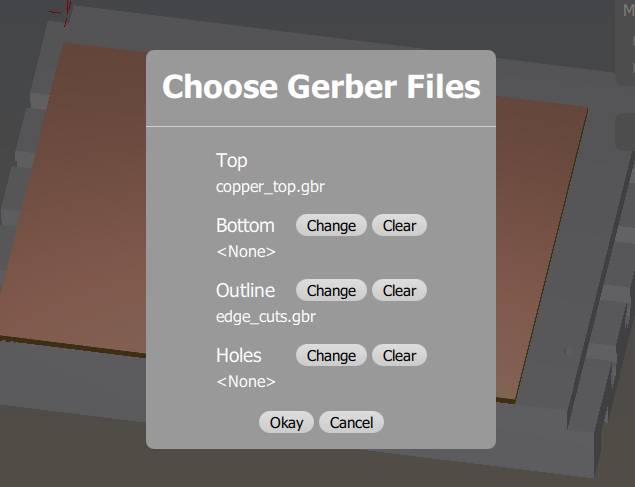 |
You have to select the different files you want to apply on that circuitboard, including one for the outline otherwise, it provides the default one, a rectangle around your design. |
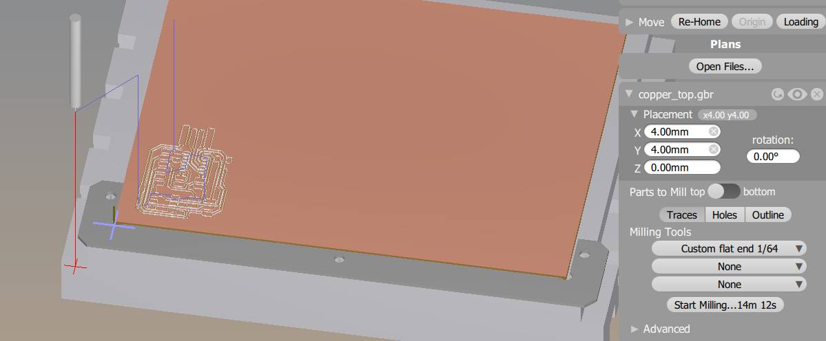 |
Now we choose what files we want to apply, here without the outline. |
 |
Or with the outline. The outline it a path that will be cut down to the stage and thus detach the circuit from the copper board so it’s better to do it as the last operation. |
 |
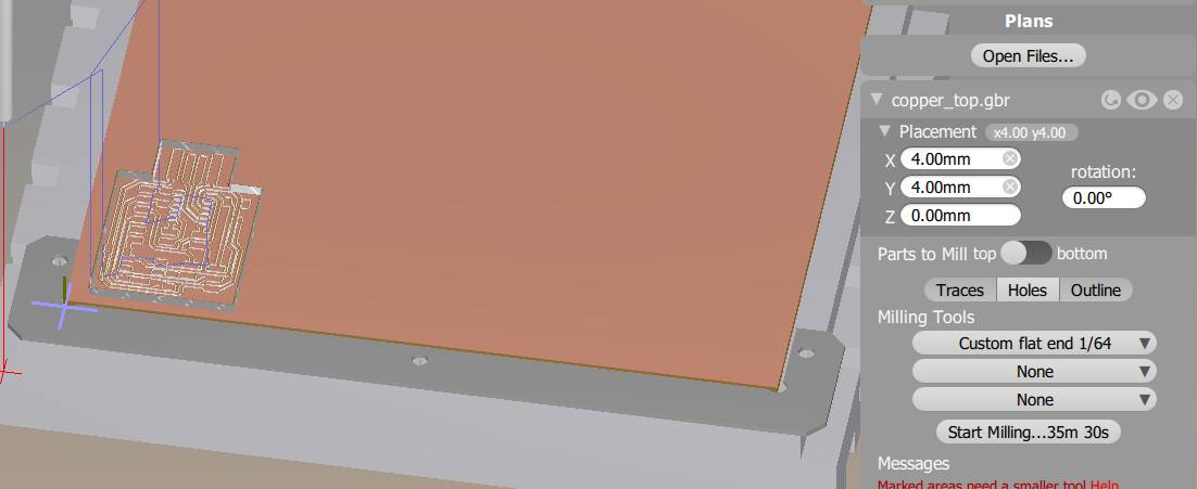
If the copper board, has already been used, you should move the pattern to a free position |
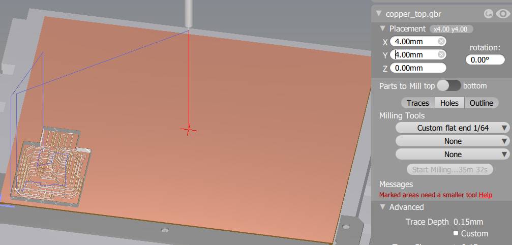 |
If we don’t move it, we will mill a non-existing area |
 |
You can move the pattern to another position using the “Placement” menu |
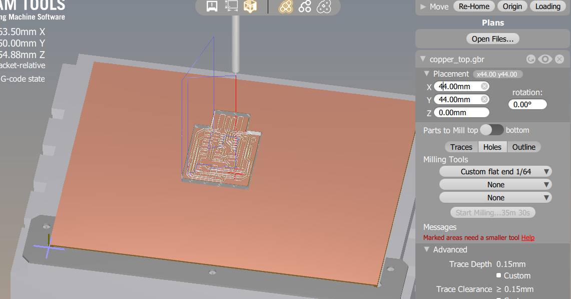 |
Once it is in a available area we continue. |
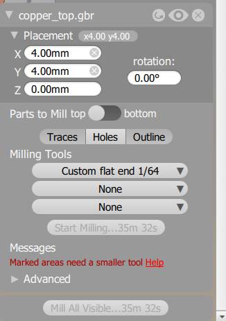 |
Now we select a tool to perform this operation, in our case the Custom 1/64 flat end. If we choose a thicker tool, we get a message saying that we cannot go in all areas required so we should select another tool. It is not necessarily a problem if you want to remove copper faster to have a clean board, easier to solder for example. |
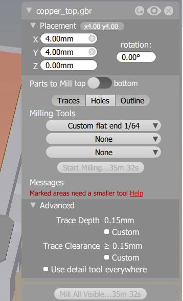 |
You can change the advanced parameters such as “Trace Depth” which is the thickness of copper that will be removed and “Trace Clearance” which is the width of copper that will be removed between passes. |
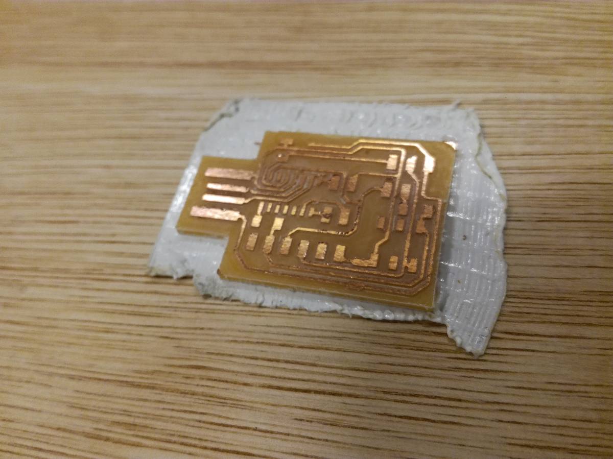 |
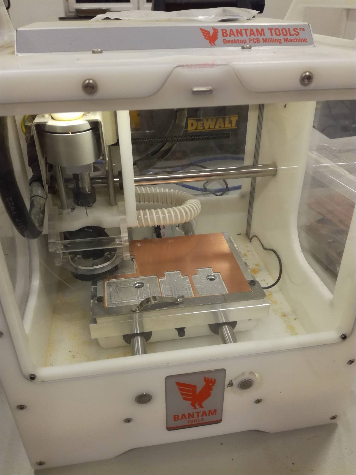
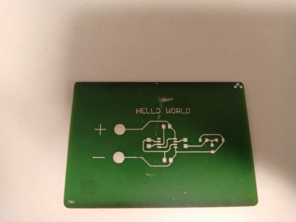
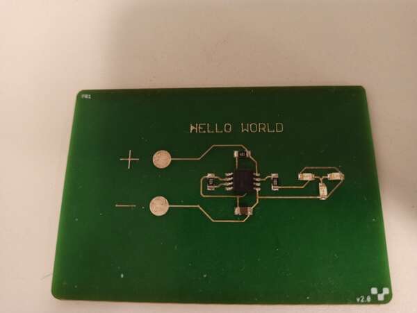
Then we close the window of the machine and click on “Start Milling” and we end up with a beautiful milled board |
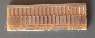
We used the files available on the fabacademy’s website to characterize the thinnest tracks we can make.

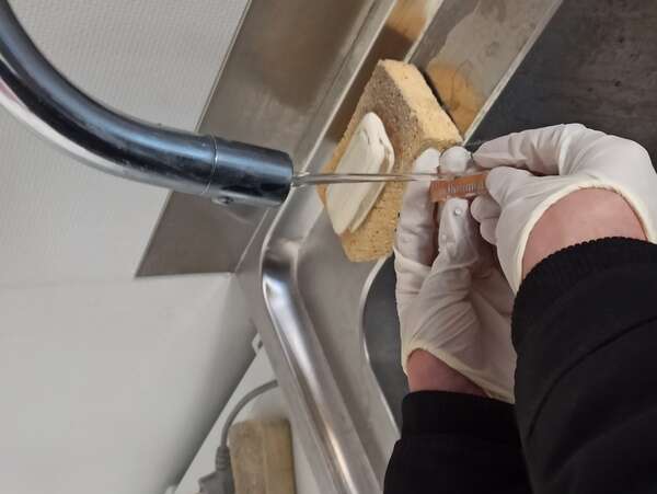
And then we covered the tracks with tin by putting the board inside a solution of tin and sulfuric acid.
That is best scenario and everything goes fine directly.
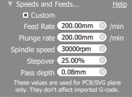
As we know it’s not always the case. In our case, we used the parameters of the tools already recorded in BantamTools software but we might need to adapt them should something change.
We used these ones :
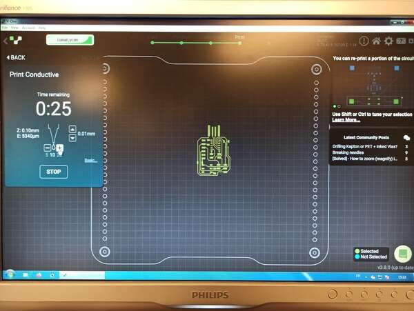
Voltera - PCB printing process
At the ULB lab we have received a Voltera a few months ago. This a new process of making boards which involve depositing a conductive ink on a board before heating it. The machine is then able to drill the holes, apply solder paste and you just need to place the components before it heats the board and solders everything for you. The boards cost a lot more (about 5$ each) and it still requires a few hours per board.
Unfortunately, due to COVID, we didn’t really use it and bad news, the conductive ink got bad in just those few months… Anyway, we tested it in the past and here is what it is capable of doing.
This little video shows how the ink looks like after a few months and as you can see, it is not suitable for board printing anymore.