12. Output devices
In this week we have to try to connect to our board some output devices and control and test them. Therefore, I have used my Atmega 328p board that I have designed and built previously with two output devices : Servo Motor and a voice recorder module.
Atmega 328p.
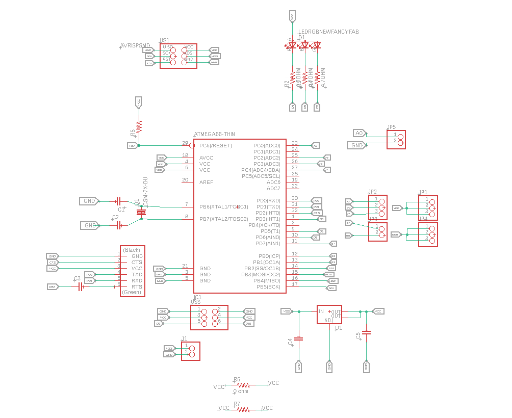
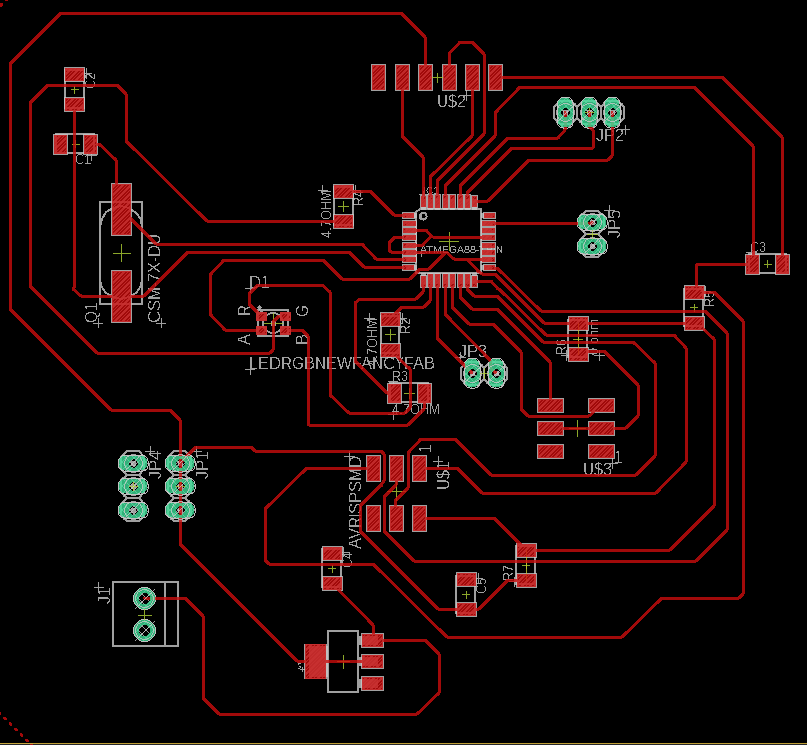
I used my board from week 7
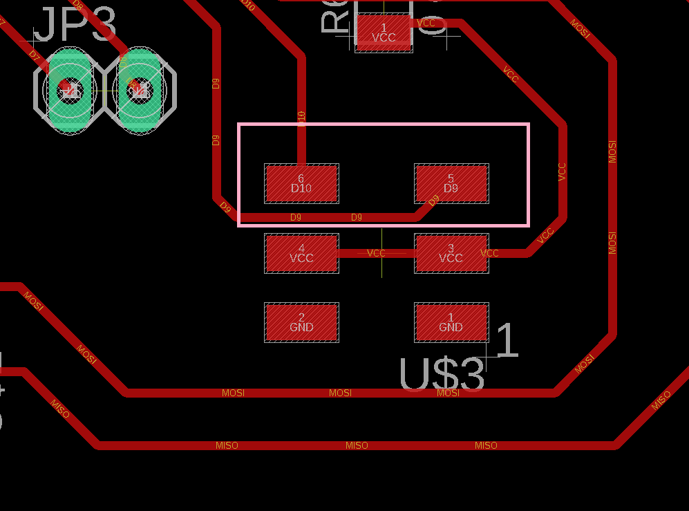
I made sure that I have several free pins for me to attach my inputs and outputs. and as you can see from the schematic diagram and the board below, I have pins D9,D10,A0,A2,A3,&A4 free.
Servo Motor MG90s.
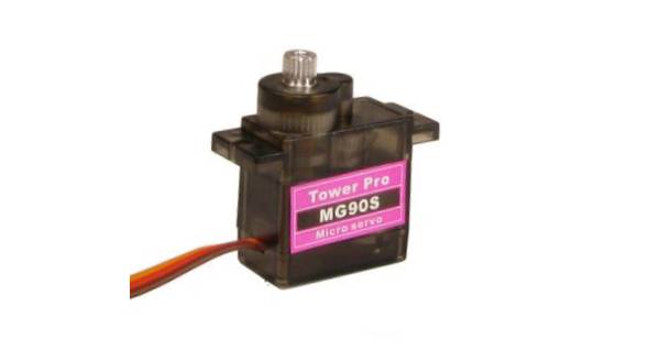
I decided to use this tiny servo motor since its light, small and easy to connect and power. the operation power is between 4.8V - 6V which can be supplied by the available VCC pins on the board. you can see the below specifications below :
- Operating Voltage: 4.8V - 6.0V.
- Torque: 4.8V: (2.20 kg-cm) - 6.0V : (2.50 kg-cm).
- Operating Speed: 4.8V: 0.11 sec/60° - 6.0V: 0.10 sec/60°
- Dimensions: Length:0.91 in (23.1 mm) | Width:0.48 in (12.2 mm) | Height:1.14 in (29.0 mm)
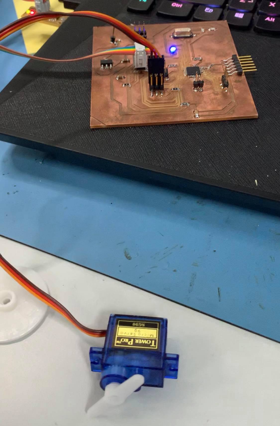
and if you look at the picture below you can see how to connect the motor to the controller.
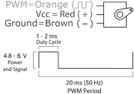
and as a result you can see there are three main pins in the servo:
-
The PWM pin: which should be connected to the pwm digital pin in microcontroller,
-
The VCC: should be connected to the power pin and should be in the range of 4.6V to 6.0V
-
The GND: this is the ground pin.
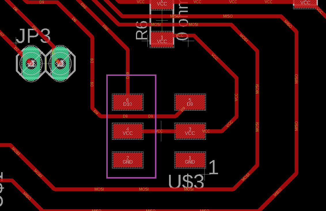
and I connected them as the following.
- The PWN pin to pin 10.
- The VCC pin to the VCC pin under pin 10.
- The GND to the GND pin under pin 10.
Coding:
I used the Arduino IDE to code the Servo Motor connected to my controller. Fist thing i did was connecting the USB programmer to the computer. the I pressed Burn Bootloader from the Tools Menu.
then I wrote the code and verified it and pressedUpload using programmer from the Sketch menu to upload the code.
code:
// Include the Servo library
#include <Servo.h>
// Declare the Servo pin
int servoPin = 10;
// Create a servo object
Servo Servo1;
void setup() {
   // We need to attach the servo to the used pin number
   Servo1.attach(servoPin);
}
void loop(){
   // Make servo go to 0 degrees
   Servo1.write(0);
   delay(1000);
   // Make servo go to 90 degrees
   Servo1.write(90);
   delay(1000);
   // Make servo go to 180 degrees
   Servo1.write(180);
   delay(1000);
}
voice recorder module ISD1820
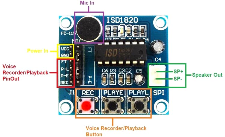
reading the datasheet, This module can be used in two different ways: either you just connect the VCC and the GND of the module to the board and use the board to supply power and using the module to record and play the voices. or you can connect those pins and the other pins to the board and program the module using the board to record and play as you wish. and to understand how to use pins on the module you can check the table below:
| Pin Name | Description |
|---|---|
| VCC | DC 2.4-5.5V |
| GND | Ground |
| FT | FeedThrough: This mode enables the Microphone to drive the speaker directly. |
| REC/REC (Button) | The REC input is an active‐HIGH record signal. The module starts recording whenever REC is HIGH. This pin must remain HIGH for the duration of the recording. REC takes precedence over either playback (PLAYLorPLAYE) signal. |
| P-E/PLAY-E (Button) | Playback, Edge‐activated: When a HIGH‐going transition is detected continues until an End‐of‐Message (EOM) marker is encountered or the end of the memory space is reached. |
| P-L/PLAY-L (Button) | Playback, Level‐activated, when this input pin level transits for LOW to HIGH, a playback cycle is initiated. |
| SPI | The SP+ and SP‐ pins provide a direct drive for loudspeakers with impedances as low as8Ω. Note: This is not Serial Parallel Interface Pins. |
| MIC | Microphone In: the microphone input transfers its signals to the on‐chip pre-amplifier. |
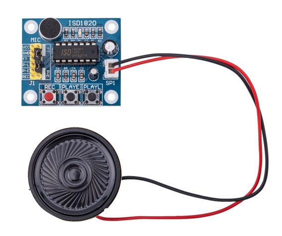
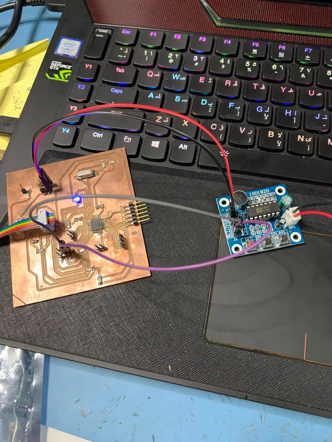
and the connection is shown in the pic below:
Also the features of ISD1820 Recorder/Playback Module are:
- Operating Voltage: Wide power supply ranges from 2.4V to 5.5V DC
- With the internal audio amplifier, this board can drive 8 Ohm 0.5W speakers directly.
- An on-board microphone.
- Dual operating modes
- Standalone mode
- Microcontroller Driven mode
- Push‐button interface, playback can be edge or level activated
- Record up to 20 seconds of audio
- Automatic power-down mode (standby mode)
- Dimensions (LxWxH) in cm 8 x 6 x 3
Coding:
First I connected the VCC and GND to the matching pins on the board. this I connected the REC pin to 9 and pin P-E to pin 10 on the board as you can see in the pictures below:
then I typed the code using Arduino IDE and uploaded it to the controller using the programmer, the code was :
int Rec = 9;

int Play = 10;

void setup()

{

pinMode(Rec, OUTPUT);

pinMode(Play, OUTPUT);

}

void loop()

{

digitalWrite(Rec, HIGH);

delay(10000);

digitalWrite(Rec, LOW);

delay(5000);

digitalWrite(Play, HIGH);

delay(100);

digitalWrite(Play, LOW);

delay(10000);

}
the results are seen in the video below:
group assignment
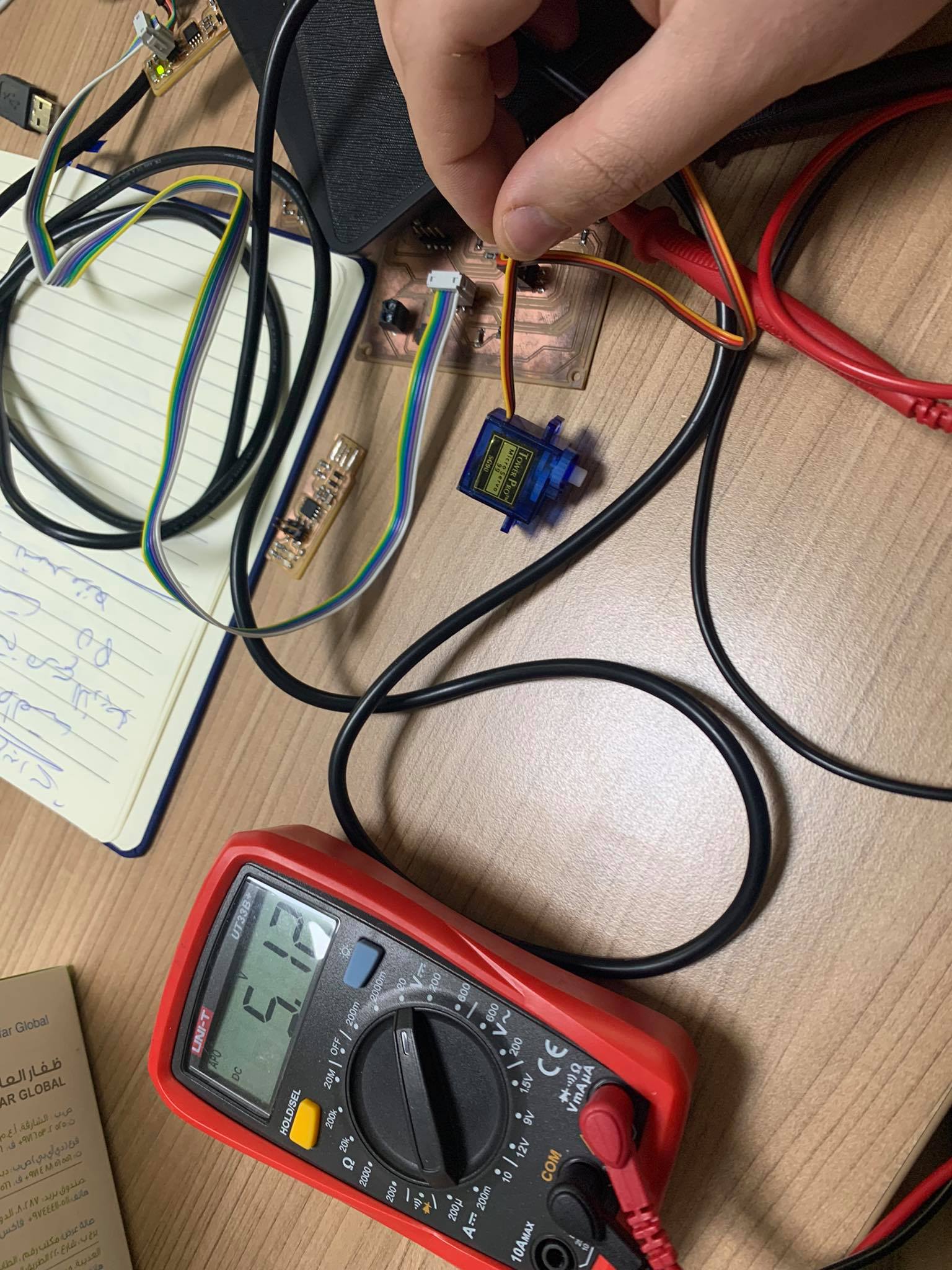
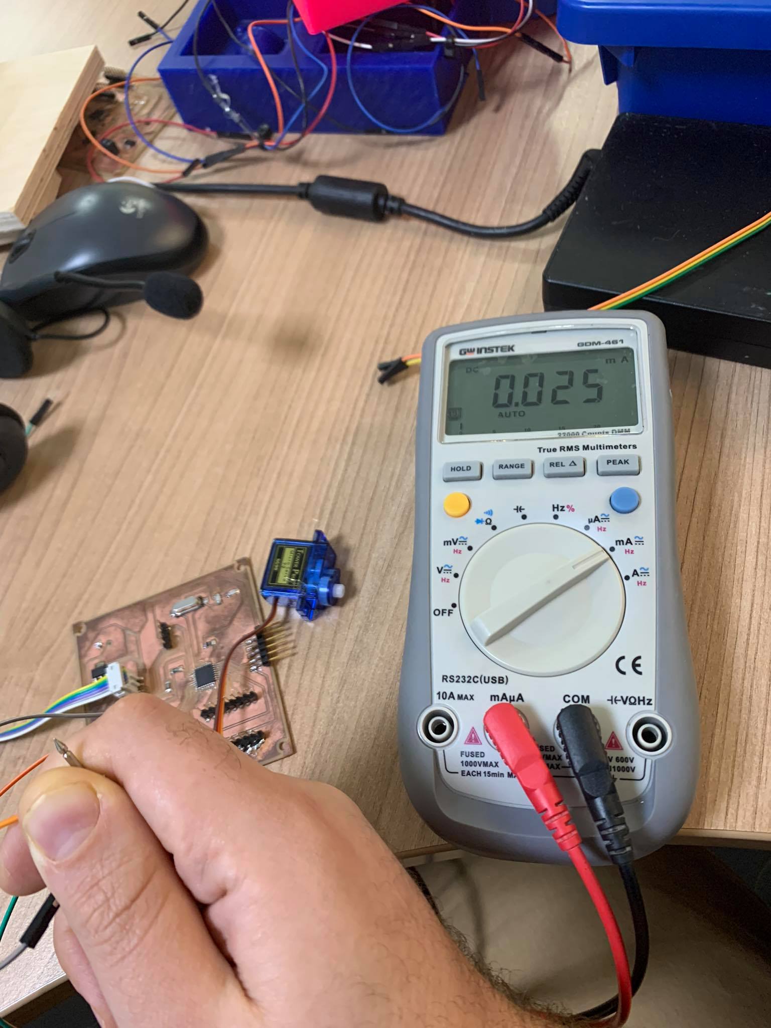
I measured the input voltage for the servo motor and it was 5V and the current 0.025 A.
So the power was P=IV. P= 5*0.025 = 0.125 W.