7. Electronics design
Although I started this week After most of the next few weeks, I’ll keep documenting in sequence. So The assignment is to redraw the hello.ftdi.44 and add atleast a button and LED and make sure the board is functioning correctly. So I have redraw the board using Eagle Software, then I have produced it with electronics and tested it with the steps showing below.
ATtiny44.
Eagle Design.
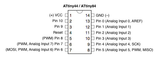
First I had to study the datasheet on ATtiny44 and understands its pins.
and to add an LED we need to calculate how much Resistance we need for it like this: (source volatge - forward voltage)/(forward current). 5-2.49/0.02 = 125.5 the closest resistor in our lab was 499.
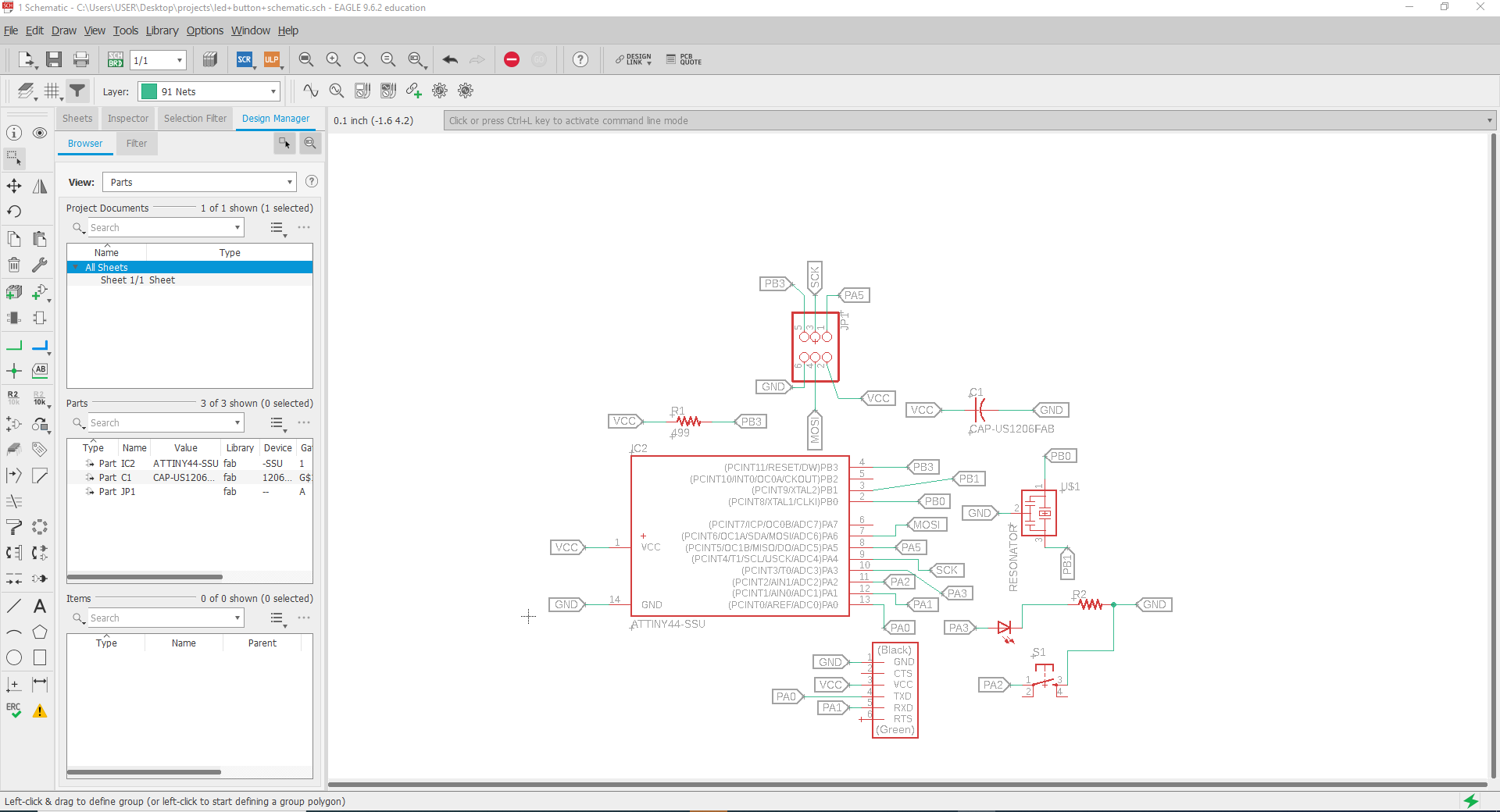
and I added the following components to the schematic.
- ATtiny44.
- Resistor “R1=10K ohms”.
- Capacetior “C1= 1 MicroF”.
- XTAL Resonator 20 MHz.
- FTDI connector (1x6 header).
- ISP connector (2x3 header).
- Resistor “R2=499 ohms”.
- LED.
- Button.
and the schematic looked like this.
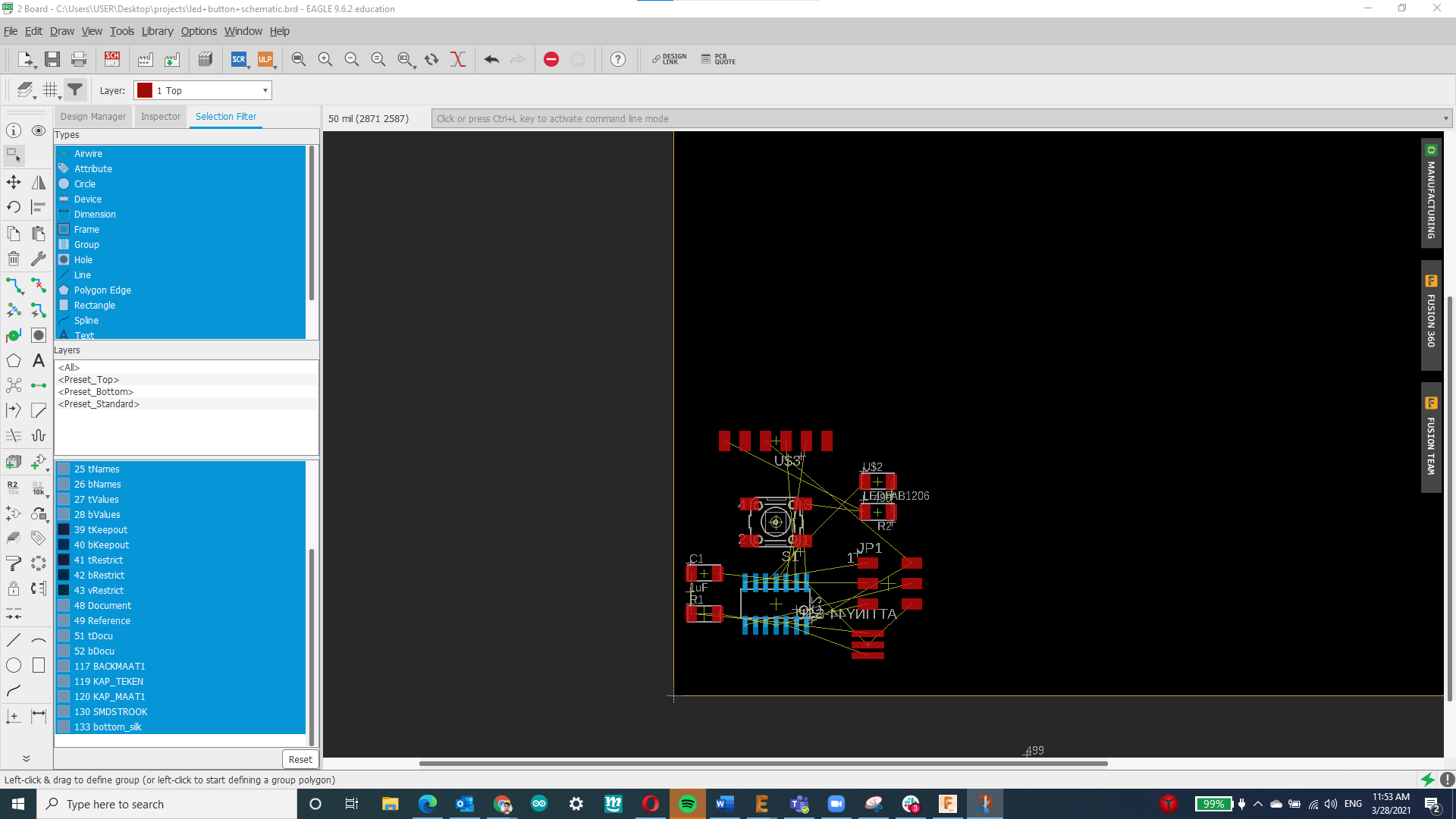
then I generated the board and it looked like this.
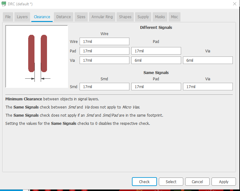
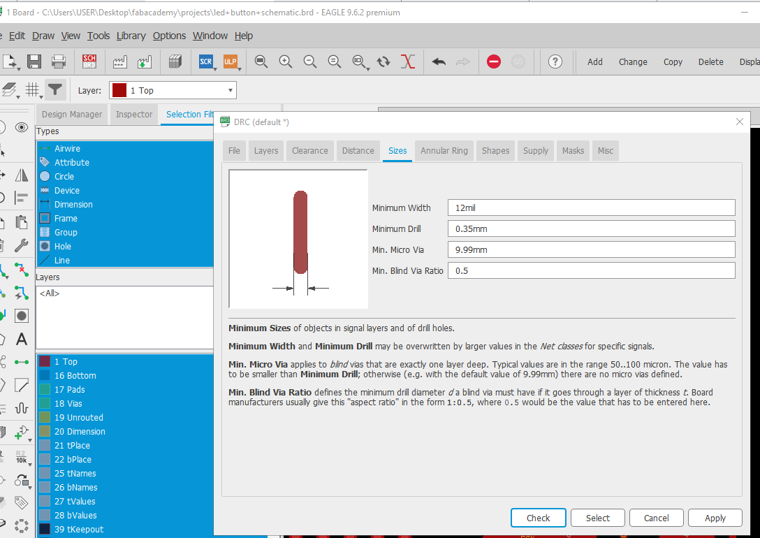
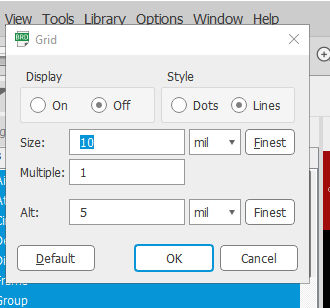
Then I changed the design rule check (DRC) before routing, I changed the clearance to 17 mil to match CNC machine settings and I did set the width size of traces to 12 mil instead of the previous 16mil which let me to have more spaces where the tracks can go , also I displayed the gird to help me in layout the components and to enhance the routing.
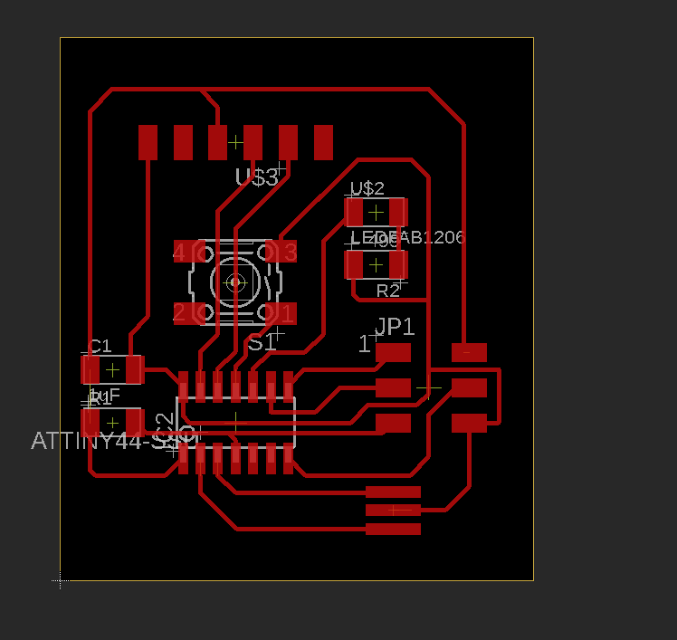
Then I did the routing and it looked like this.
Then I edited Layer settings: hide all the layers except Top, Pads and Dimensions as shown below:
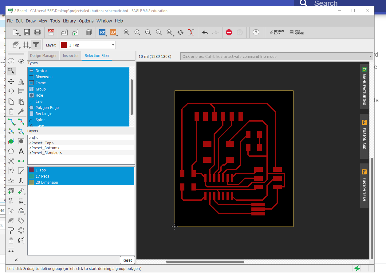
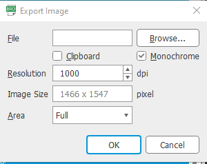
Then I exported the PNG image from file>export> image, with resolution of 1000 dpi Monochrome and full area.
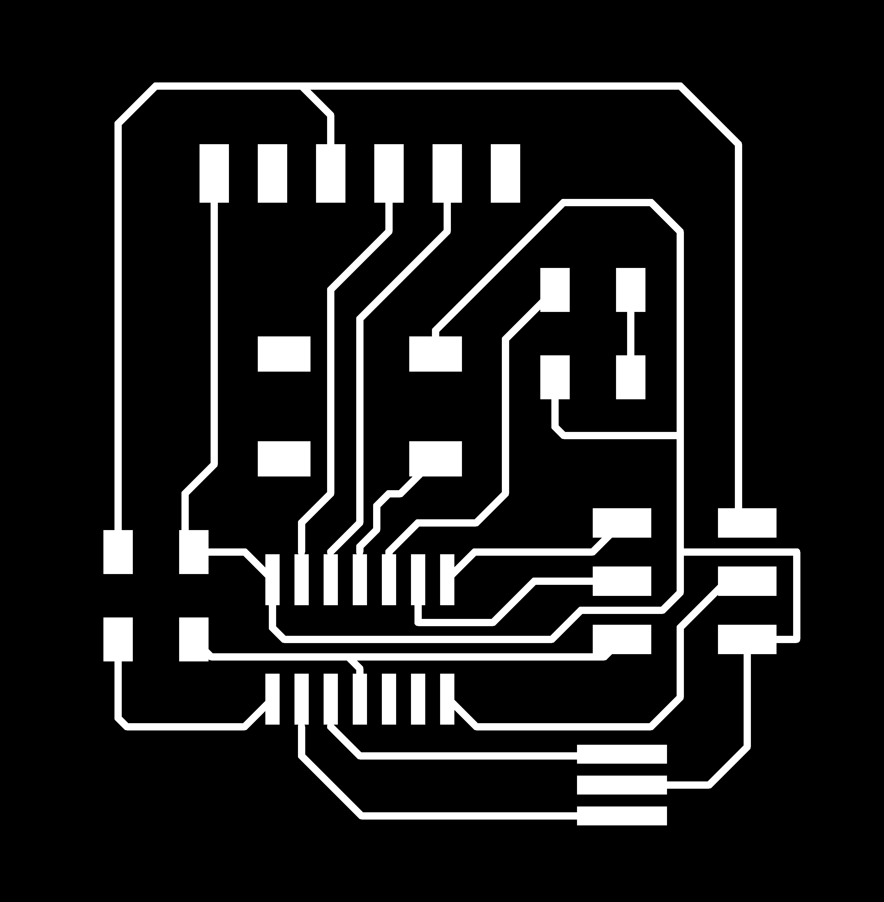
Then I got the traces and outline via GIMP software:

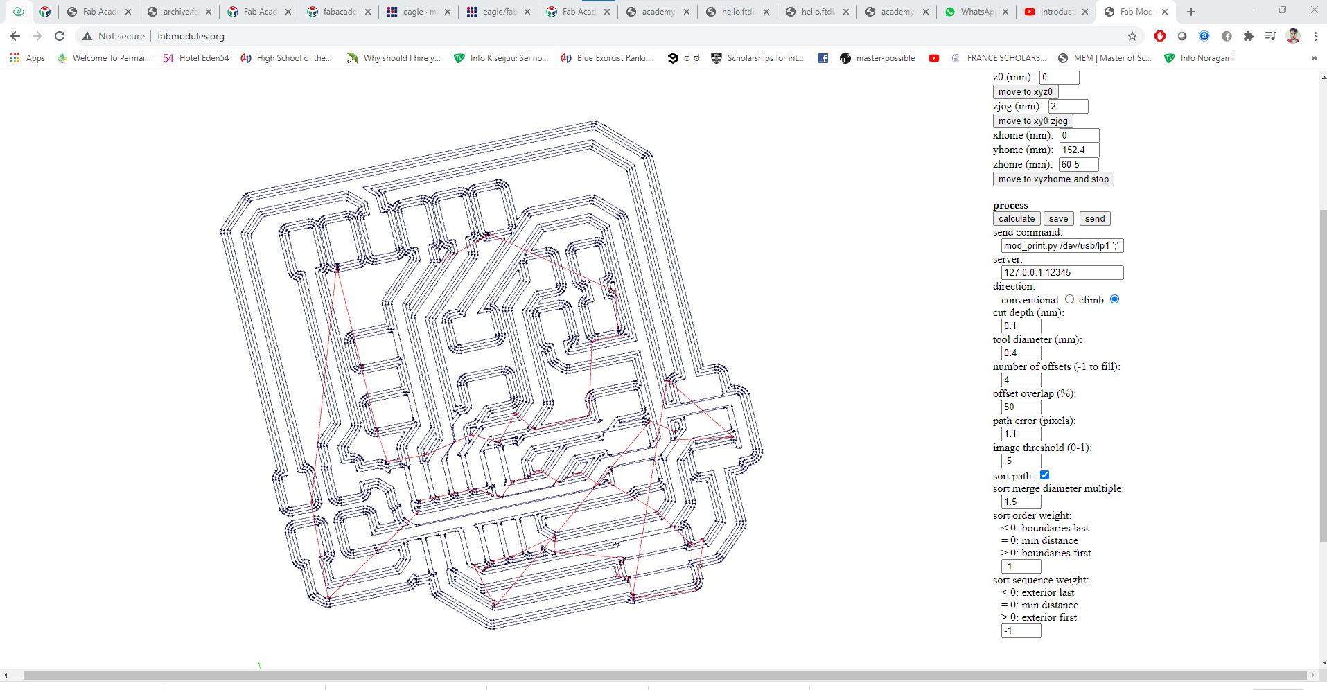
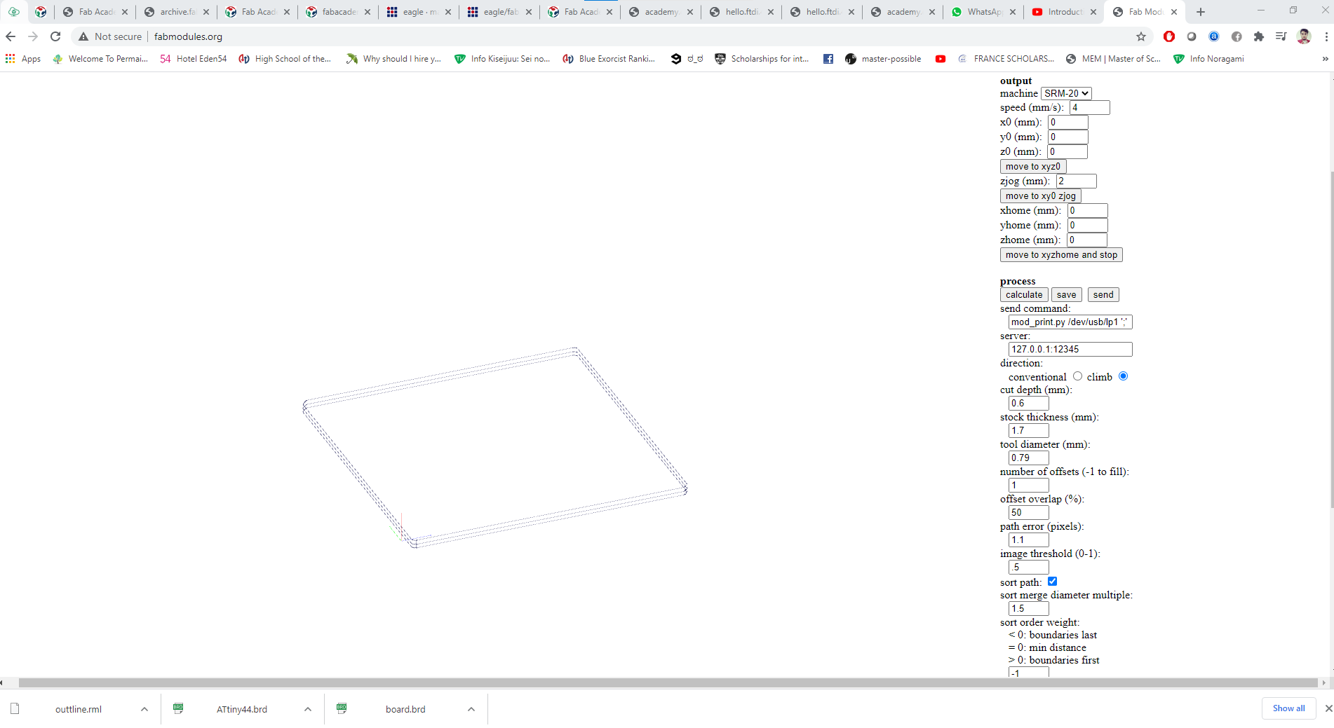
then I imported the files to fab modules to prepare rml files for milling.
Fabrication.
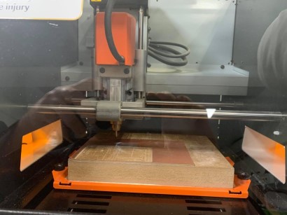
I produced the board with Ronald srm_20 milling machine and followed same steps in week05
set up the Settings in the Ronald srm_20 milling machine. and mounted one sided FR1 plate to be milled.
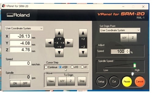
then seting up the Vpanel for SRM-20 app and setting up home position fort three cordinates.
for Z Zeoring:
I lowered the milling bit down enough to be close to touch the board. then I un-screw the milling bit and lowered it to touch the top of the plate, and set the zero Z value. This step is done to make sure that the milling bit will be able to touch the top sothe engraving is done right.
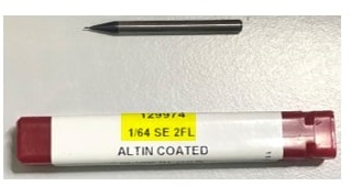
The first milling (1/64) bit for traces is shown here:
then I started milling.
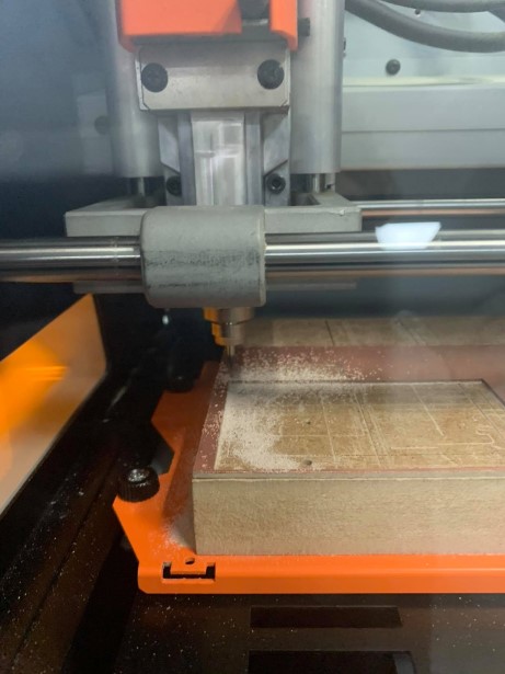
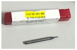
Then I replaced the (1/64) with (1/32). to do the cutting by keeping the X,Y zeroes the same but rezeoring the Z axis with the (1/32).
and the result is here
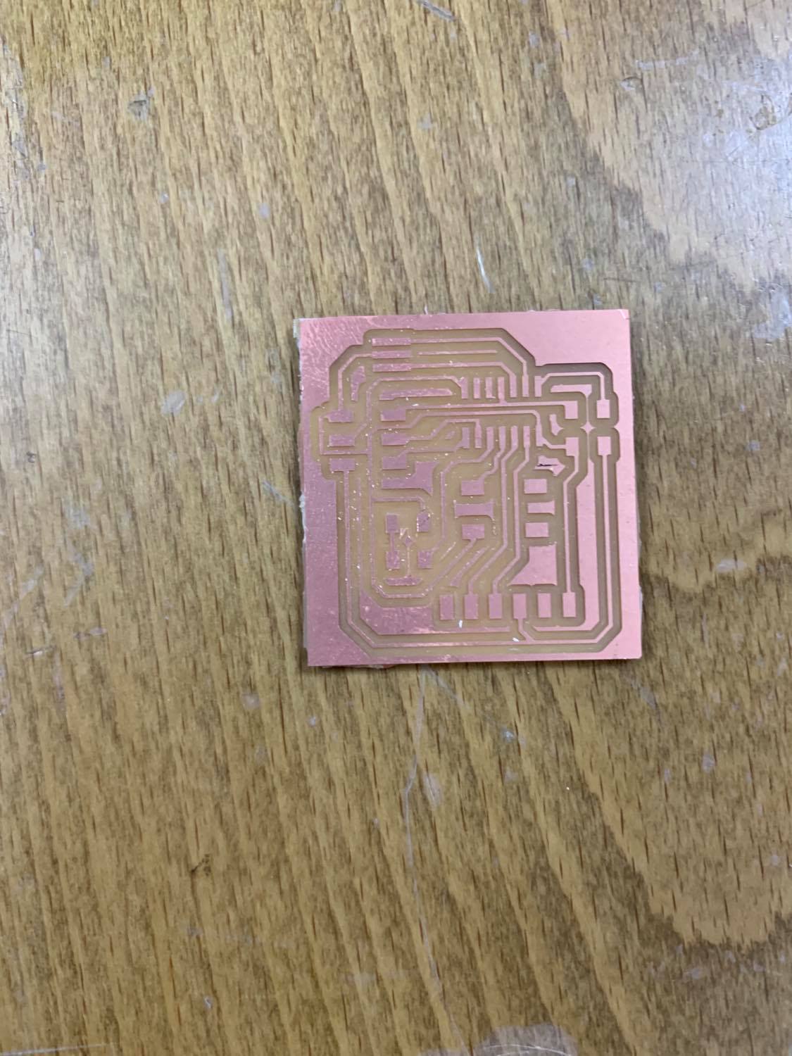
Electronics.
I gathered the mentioned-above components to solder.
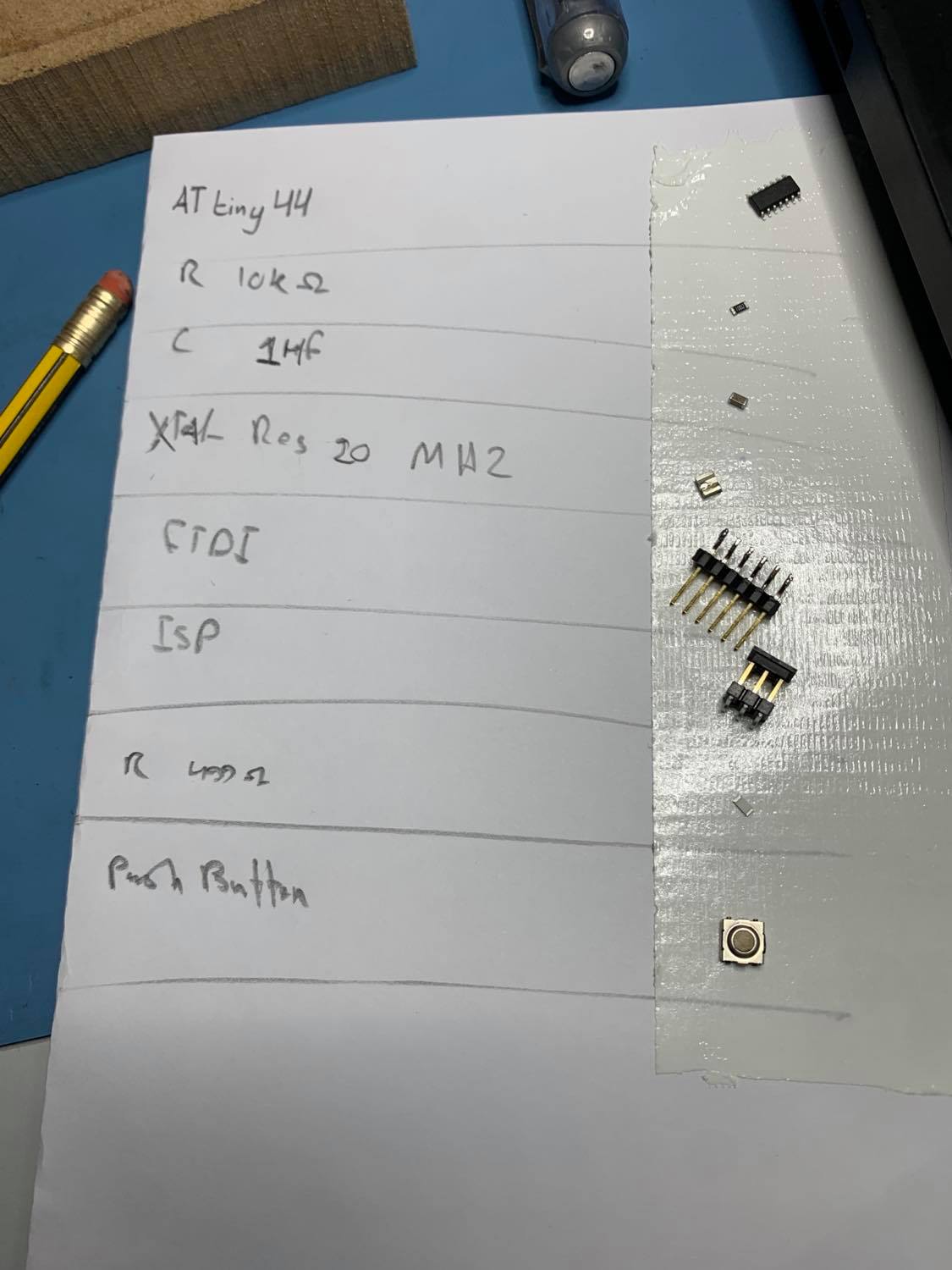
then I soldered them.
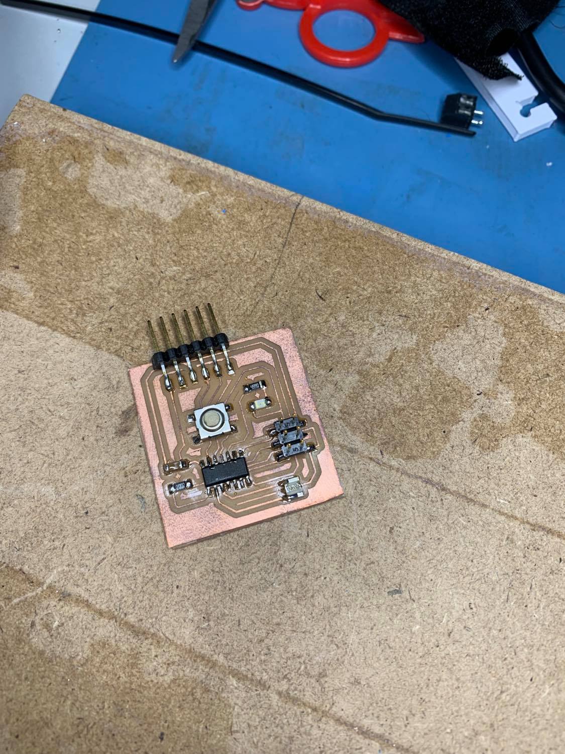
this is a video of uploading an empty code to the board to test it.
Atmega 328p.
Designing.
I have used Neil’s design hello.arduino.328P and also used Waleed’s Board with the following modifications.
1- added 6 free pins for digital and analog inputs and outputs.
2- RGB light as output.
3- LED as output.
4- several VCC and GND pins.
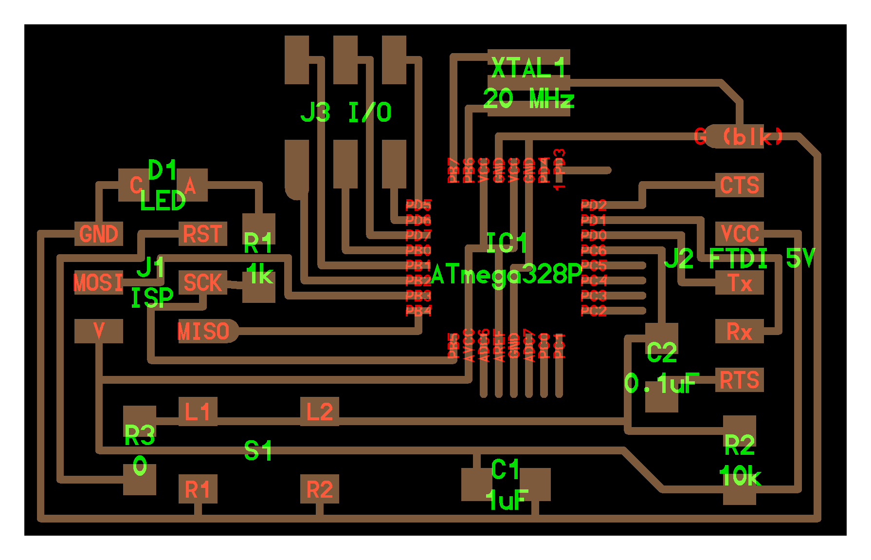
I made sure that I have several free pins for me to attach my inputs and outputs. and as you can see from the schematic diagram and the board below, I have pins D9,D10,A0,A2,A3,&A4 free.
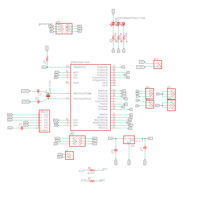
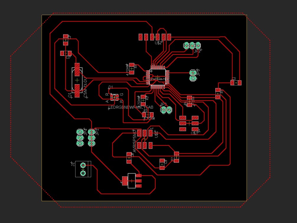
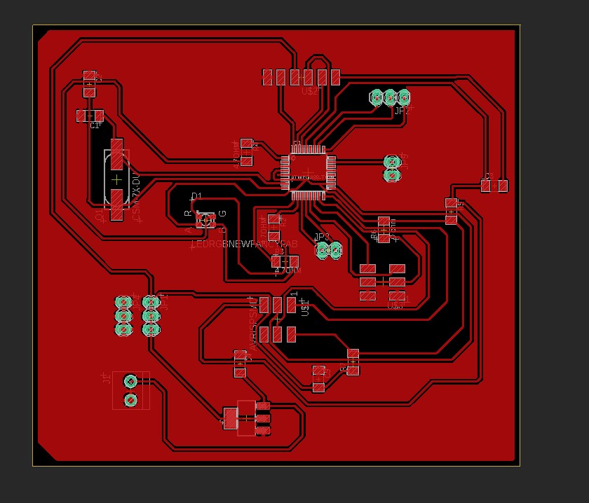
Then I inverted the schematic to have all the empty spaces as common grounds.
preparing for milling.
This time I used FlatCam which can open Gerber, excellon or G-code. instead of fabmodules.
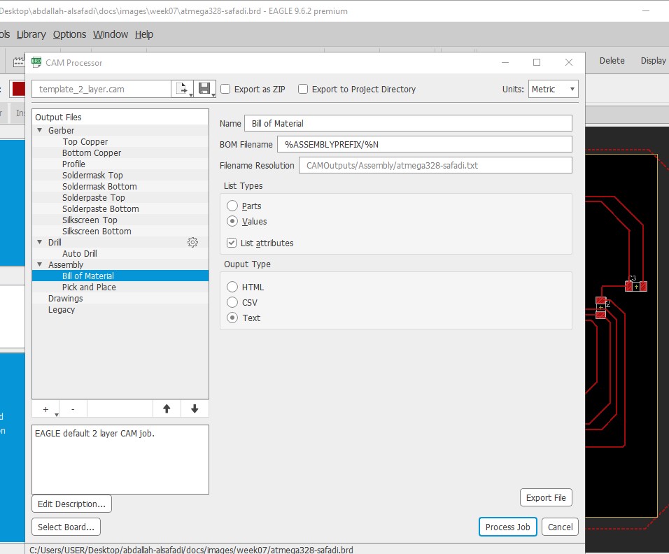
then to export the file to flatcam, I used the manufacturing tool from the application, and launch cam to open the cam processor, then generate and export the Gerber files.
then the 3 processes I did on flat cam to generate the CNC files are:
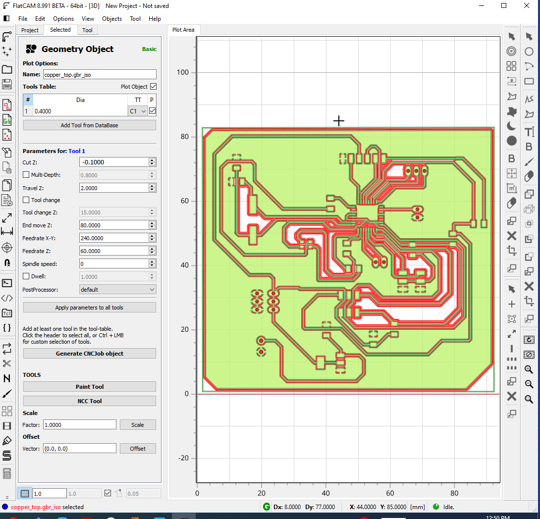
- Gerber files for traces.
Isolation Geometry:
-
tool diameter: 0.4 mm.
-
passes: 4.
-
overlap: 60%.
-
check combine box.
CNC object files.
-
cut Z: -0.1 mm.
-
End move Z: 60.
-
Feedrate X-Y: 240.
-
Feedrate Z: 80.
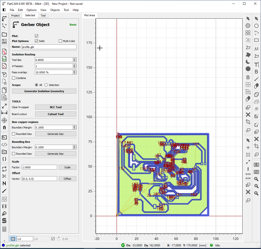
- Gerber files for outline.
Isolation Geometry:
-
tool diameter: 0.8 mm.
-
passes:1.
-
overlap: 60%.
-
check combine and external isolation box.
CNC object files:
-
cut Z: -1.7 mm.
-
End move Z: 60.
-
Feedrate X-Y: 240.
-
Feedrate Z: 80.
-
Multi-depth: 0.7.
- Excellon files for drilling.
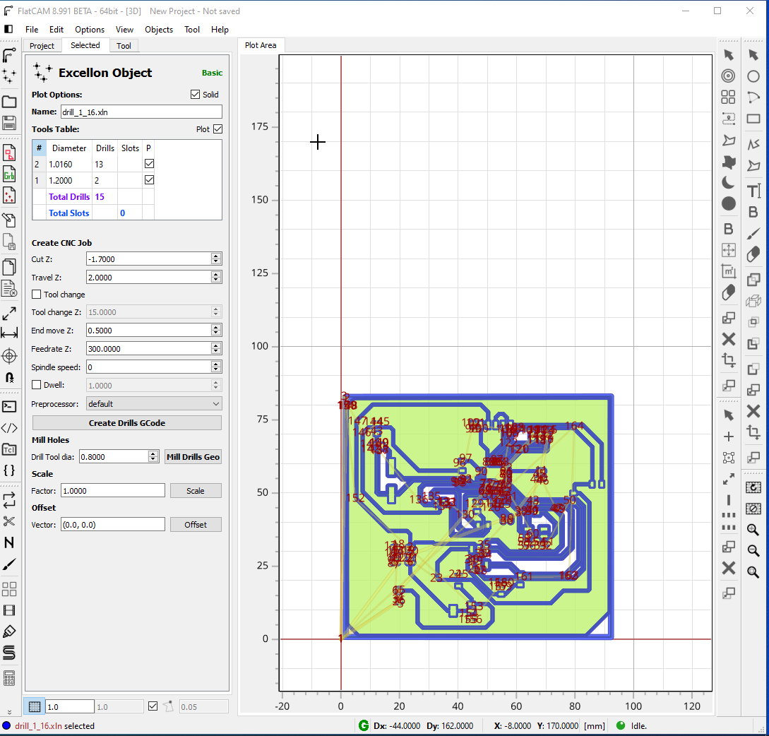
Then genrate CNC g-code files.
milling.
I used similar step to milling the Attiny44.
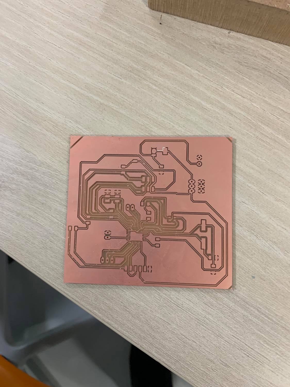
the results was like this.
ELectronics.
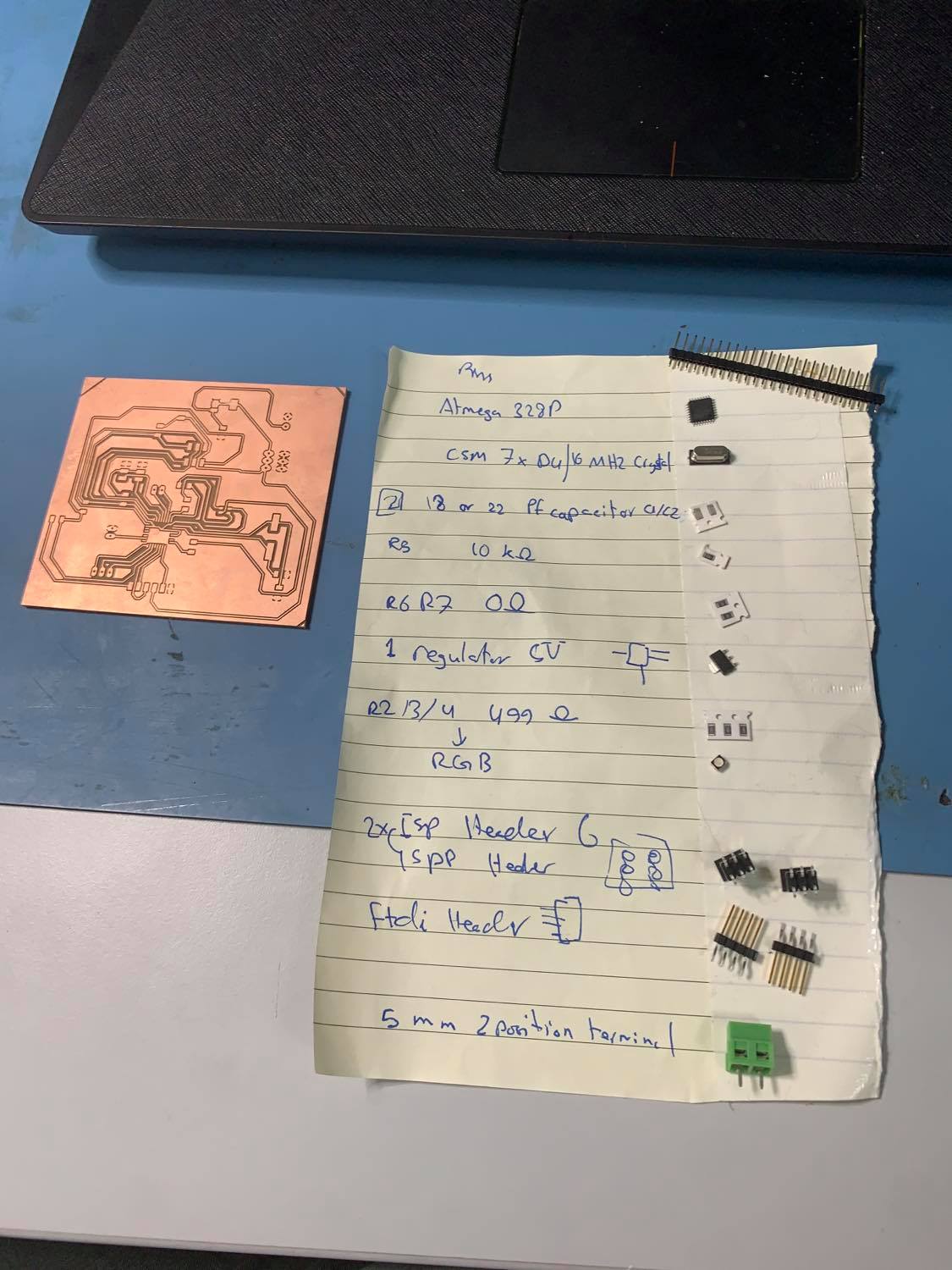
First I gathered the following components.
then I soldered them.
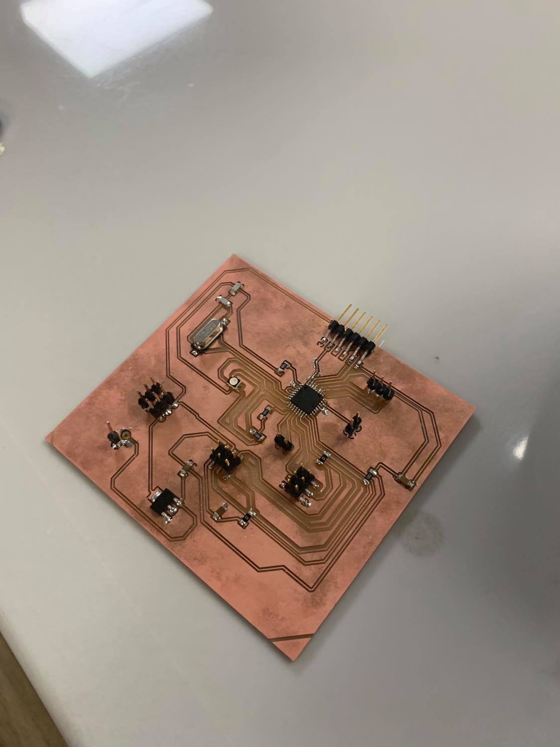
Here is a video from week 9 showing the board working.
## files.
Group assignment.
I measured the voltage for Attiny44 input and it was 5V.