- Group Assignment:
- compare the performance and development workflows
for other architectures
- compare the performance and development workflows
- Individual Assignment:
- Read a microcontroller data sheet
- program your board to do something,
with as many different programming languages
and programming environments as possible
- Link to the group assignment page
- Document what I learned from reading a microcontroller datasheet
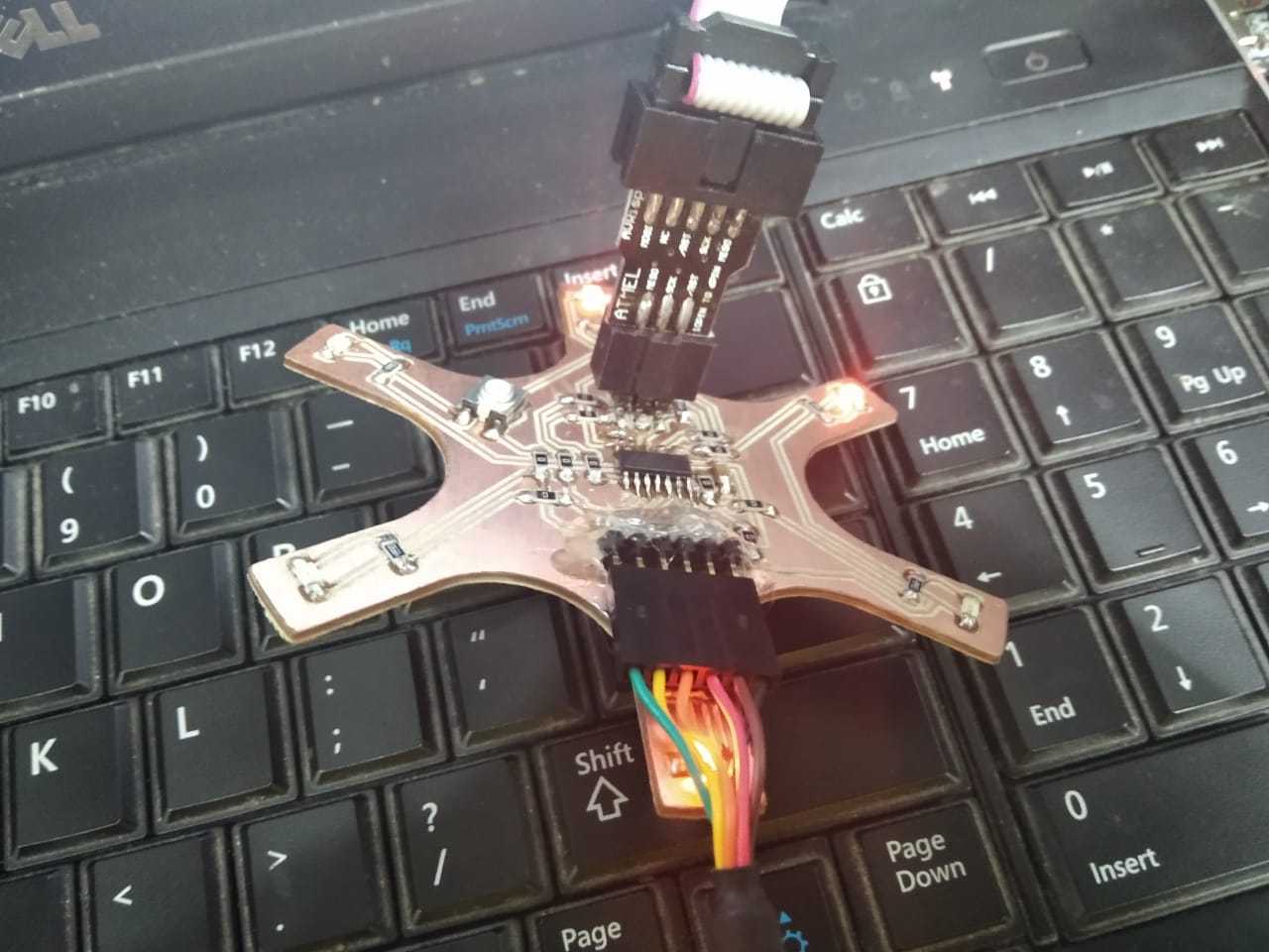
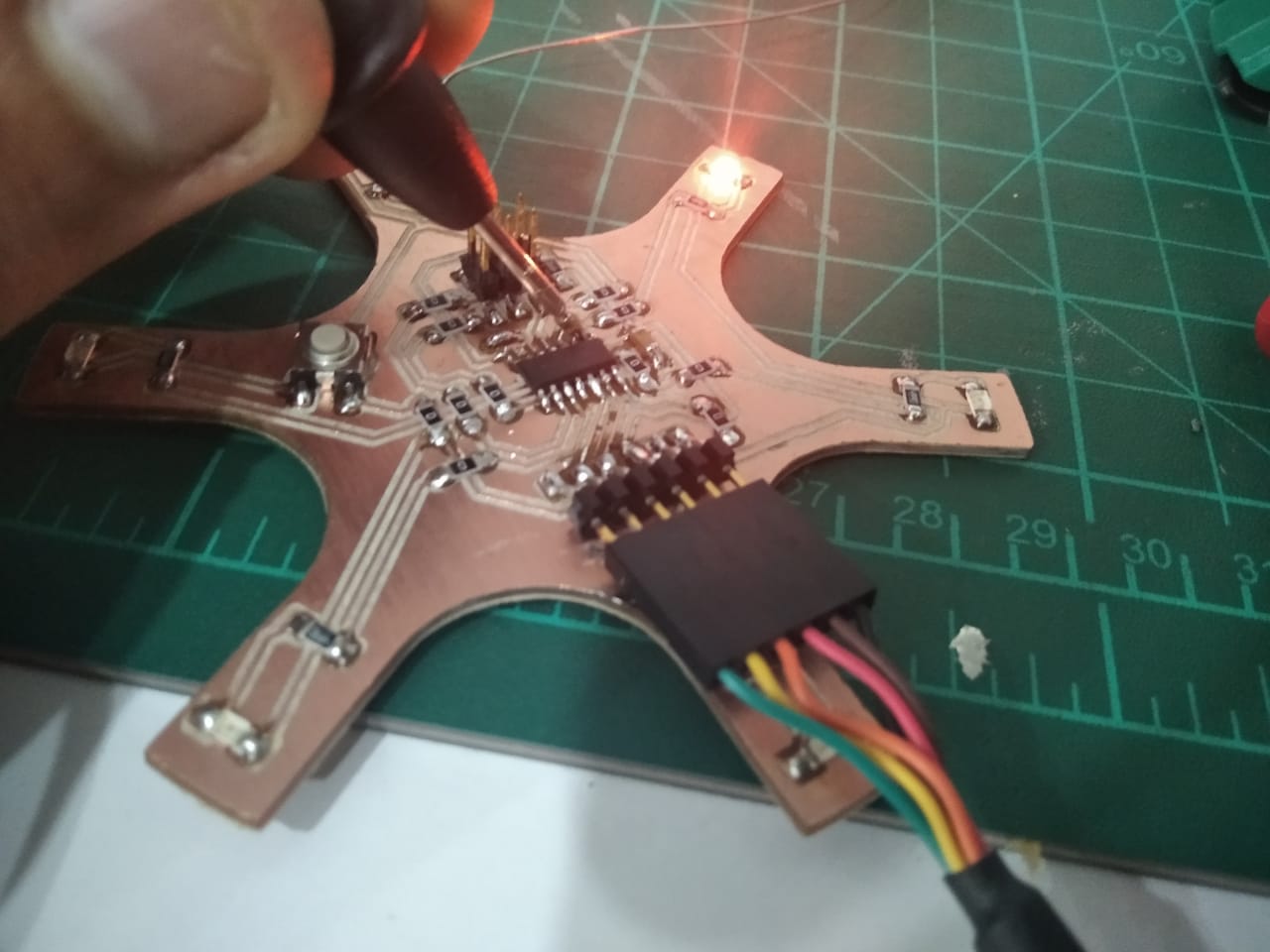
- Program my board
- Describe the programming process/es I used
- Include my source code
- Include a short ‘hero video’ of my board
- DDRx register
- PORTx register
- PINx register
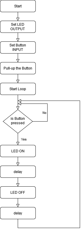
- To output data : when port is configured as output
When you set bits in DDRx to 1, corresponding pins becomes output pins. Now you can write data into respective bits in PORTx register. This will immediately change state of output pins according to data you have written. Example:PORTB = 0xFF;will write HIGH on every pin that was set as output. - To activate/deactivate pull up resistors – when port is configures as input
When you set bits in DDRx to 0, i.e. make port pins as inputs, then corresponding bits in PORTx register are used to activate/deactivate pull-up registers associated with that pin. In order to activate pull-up resister, set bit in PORTx to 1, and to deactivate (i.e to make port pin tri stated) set it to 0.
Group Assignment
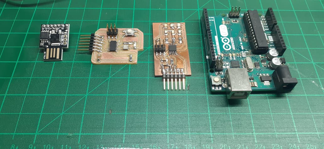
In this assignment we are going to compare the performance between Arduino UNO board, Attiny44, attiny85.

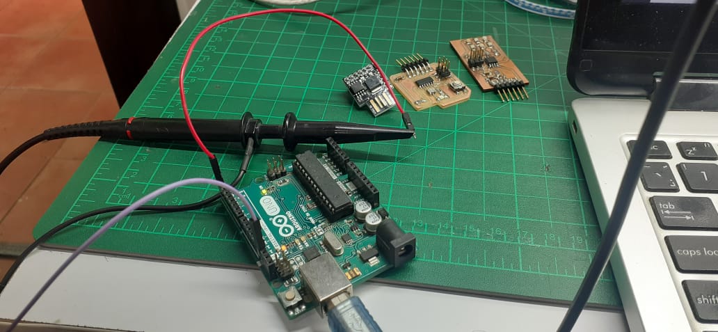

Tools used
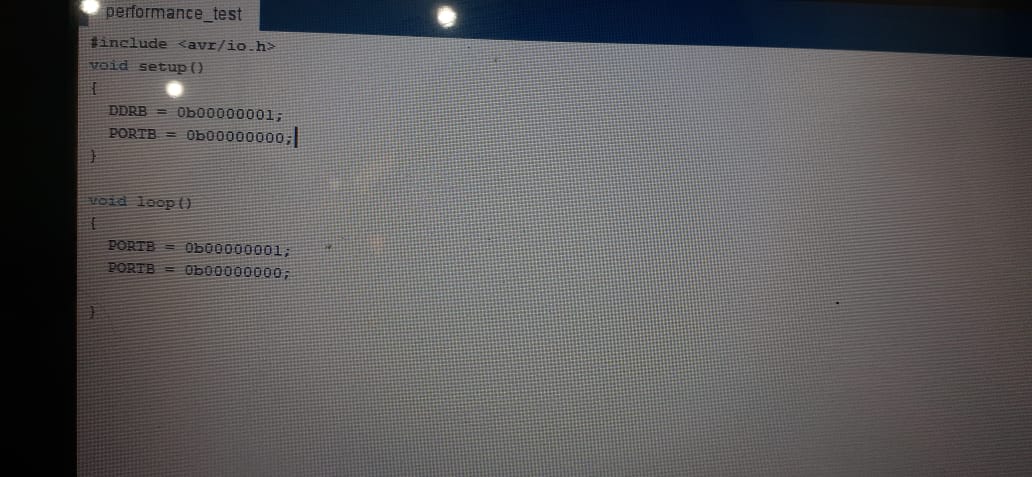
We are going to use the Arduino IDE for C and Arduino C programming and display the frequency on the oscilliscope.The code
The code sets the pin as output and switchs the pin on then off in a loop
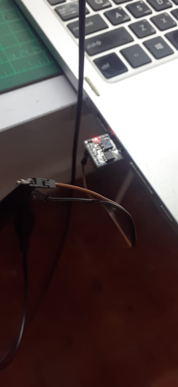
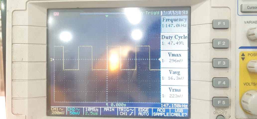
Test 1: Attiny85 @ 16.5MHz by Arduino C
We observed a frequency of 147 KHz which is very low. Our guess was that the Arduino libraries are making the switching slower.
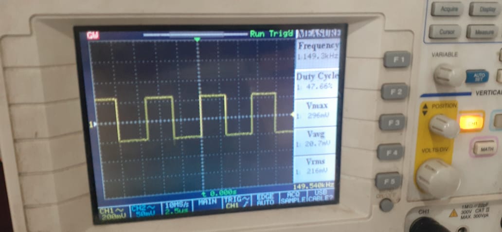
Test 2: Arduino Uno @ 16MHz by Arduino C
We observed a square wave with a frequency of 149 KHz which is higher than the results of test 1.
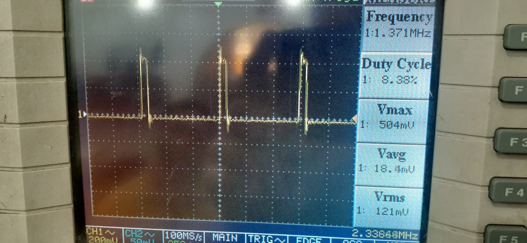
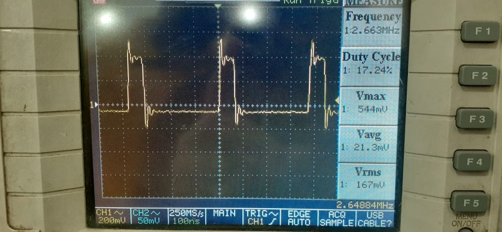
Test 3: Attiny85 programmed by C and Arduino UNO programmed by C.
Now we programmed both boards using C language in which we access the registers directly and observed the difference. the difference is very high. now the frequency of both boards is above 2 MHz.
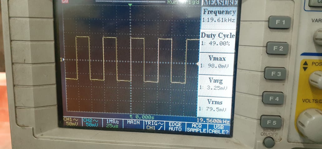
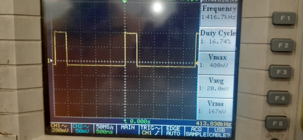
Attiny44 @ 20MHz
The frequency with arduino libraries is 19KHz meanwhile with C language is 413MHz.
Understanding ATTiny 45
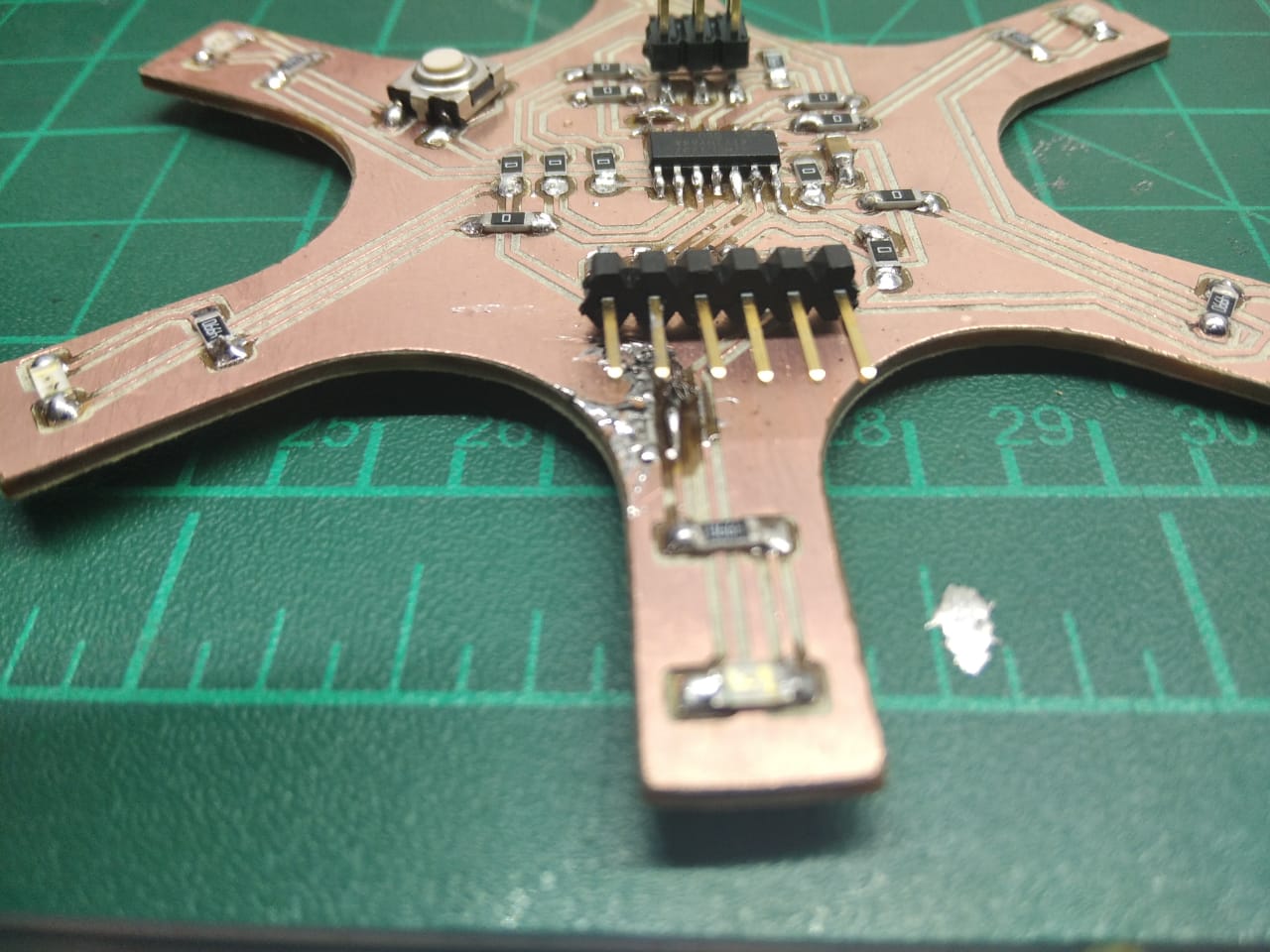
I have used the Circuit of Week 6 if you want check how I made it
Begining with the AVR
 Microcontrollers are used in many embedded systems applications, let’s look at some consumer products like the air conditioner, the brain of it is a microcontroller that responsible for receiving sensors data like a temperature sensor that senses the current room temperature, turn that input into series of commands to go to the air conditioner compressor to work or not. Or even the microcontroller in your universal remote control translates your key presses into a precise series of pulses for an infrared LED that tells the microcontroller inside your television to change the channel or increase the volume.
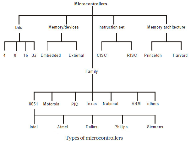
When it comes to choosing your microcontroller, There are a lot of options out there. There are so many microcontroller families are available. Those are 8051, PIC, AVR, ARM, etc. each microcontroller family has its own specifications like the processor speed, flash memory size, RAM size, ...etc.
Here's what's inside the ATTiny44:
| Flash (program memory) | 4096 bytes |
|---|---|
| RAM | 256 bytes |
| EEPROM | 256 bytes |
| GPIO Pins | 8 + RST + XTAL1 + XTAL2 |
| ADC Channels | 8 |
| PWM Channels | 4 |
| Clock options | Internal 1/8mhz, external crystal or clock* up to 20mhz |
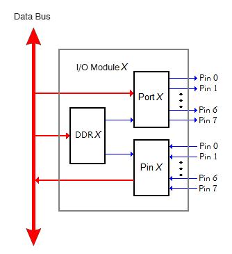
Atmel AVR is 8 bit microcontroller. All its ports are 8 bit wide. Every port has 3 registers associated with it each one with 8 bits. Every bit in those registers configure pins of particular port. Bit0 of these registers is associated with Pin0 of the port, Bit1 of these registers is associated with Pin1 of the port, …. and like wise for other bits.
These three registers are as follows : (x can be replaced by A,B,C,D as per the AVR you are using)
DDRx (Data Direction Register) configures data direction of port pins. Means its setting determines whether port pins will be used for input or output. Writing 0 to a bit in DDRx makes corresponding port pin as input, while writing 1 to a bit in DDRx makes corresponding port pin as output. Example: to make lower nibble(half byte) of port B as output and higher nibble(half byte) as input :
PINx register
PINx (Port IN) used to read data from port pins. In order to read the data from port pin, first you have to change port’s data direction to input. This is done by setting bits in DDRx to zero. If port is made output, then reading PINx register will give you data that has been output on port pins.
PORTx register
PORTx is used for two purposes:
We can visualise the relation between the DDR, PIN, and PORT like following:
DDRx (Data Direction Register) configures data direction of port pins. Means its setting determines whether port pins will be used for input or output. Writing 0 to a bit in DDRx makes corresponding port pin as input, while writing 1 to a bit in DDRx makes corresponding port pin as output. Example: to make lower nibble(half byte) of port B as output and higher nibble(half byte) as input :
DDRB = 0b00001111;
PINx register
PINx (Port IN) used to read data from port pins. In order to read the data from port pin, first you have to change port’s data direction to input. This is done by setting bits in DDRx to zero. If port is made output, then reading PINx register will give you data that has been output on port pins.
PORTx register
PORTx is used for two purposes:
Arduino-C Code
The Arduino code is pretty straightforward. You don't need to remember which DDR, PIN, or PORT. You just set the
And After I made sure from the logic and the pins , I begin to write the complete code
The Logic of the code is too simple , All I made is to make the lamps turn on and turn off every beriod of time
I strte to make a simple version of code to test the pins and the function of the code
pinMode in the void setup() section, which will be executed once, then write your code sequence in the void loop() section
and it will run repeatedly. Here are some quotes about the most important functions in the Arduino-C language.
pinMode
Configures the specified pin to behave either as an
Syntax:
digitalWrite
Write a
Syntax:
digitalRead
Reads the value from a specified digital pin, either
Syntax:
delay
Pauses the program for the amount of time (in milliseconds) specified as parameter. (There are 1000 milliseconds in a second.)
Syntax:
The Logic of the code is too simple , All I made is to make the lamps turn on and turn off every beriod of time
I strte to make a simple version of code to test the pins and the function of the code
Configures the specified pin to behave either as an
INPUT or an OUTPUT. It is possible to enable the internal pullup resistors with the mode INPUT_PULLUP. Additionally, the INPUT mode explicitly disables the internal pullups.
Syntax:
pinMode(pin, state)
digitalWrite
Write a
HIGH or a LOW value to a digital pin. Syntax:
digitalWrite(pin, value)
digitalRead
Reads the value from a specified digital pin, either
HIGH or LOW.
Syntax:
digitalRead(pin)
delay
Pauses the program for the amount of time (in milliseconds) specified as parameter. (There are 1000 milliseconds in a second.)
Syntax:
delay(ms)
  int Led1 = 10

void setu() {
  pinMode (Led1 ,OUTPUT);
  digitalWrite (Led1 , HIGH);
}

void loop () {

  digitalWrite(Led1, HIGH);
  delay(1000);
  digitalWrite(Led1 , LOW);
  delay(1000);


}
And After I made sure from the logic and the pins , I begin to write the complete code
int Led2 = 10;
int Led1 = 9;
int Led3 = 2;
int Led4 = 8;
int Led5 = 3;
int Pushbutton = 7;
 void setup() {

  pinMode (Led1 , OUTPUT);
  pinMode (Led2 , OUTPUT);
  pinMode (Led3 , OUTPUT);
  pinMode (Led4 , OUTPUT);
  pinMode (Led5 , OUTPUT);
  pinMode (Pushbutton , INPUT);
  digitalWrite(Led1 , LOW);
  digitalWrite(Led2 , LOW);
  digitalWrite(Led3 , LOW);
  digitalWrite(Led4 , LOW);
  digitalWrite(Led5 , LOW);
    digitalWrite(Led5 , LOW);
    digitalWrite(Pushbutton , 1);

}

void loop() {
digitalWrite(Led1 , HIGH);
  delay (300);
  digitalWrite(Led2 , HIGH);
  delay (300);
  digitalWrite(Led3 , HIGH);
  delay (300);
  digitalWrite(Led4 , HIGH);
  delay (300);
  digitalWrite(Led5 , HIGH);
  delay (300);
  digitalWrite(Pushbutton , HIGH);
  delay (300);
  digitalWrite(Led1 , LOW);
  digitalWrite(Led2 , LOW);
  digitalWrite(Led3 , LOW);
  digitalWrite(Led4 , LOW);
  digitalWrite(Led5 , LOW);
  delay (300);
/*  ------------------- */
  digitalWrite(Led1 , HIGH);
  delay (250);
  digitalWrite(Led2 , HIGH);
  delay (250);
  digitalWrite(Led3 , HIGH);
  delay (250);
  digitalWrite(Led4 , HIGH);
  delay (250);
  digitalWrite(Led5 , HIGH);
  delay (250);
  digitalWrite(Pushbutton , HIGH);
  delay (250);
  digitalWrite(Led1 , LOW);
  digitalWrite(Led2 , LOW);
  digitalWrite(Led3 , LOW);
  digitalWrite(Led4 , LOW);
  digitalWrite(Led5 , LOW);
  delay (250);
  /*------------------ */
  digitalWrite(Led1 , HIGH);
  delay (200);
  digitalWrite(Led2 , HIGH);
  delay (200);
  digitalWrite(Led3 , HIGH);
  delay (200);
  digitalWrite(Led4 , HIGH);
  delay (200);
  digitalWrite(Led5 , HIGH);
  delay (200);
  digitalWrite(Pushbutton , HIGH);
  delay (200);
  digitalWrite(Led1 , LOW);
  digitalWrite(Led2 , LOW);
  digitalWrite(Led3 , LOW);
  digitalWrite(Led4 , LOW);
  digitalWrite(Led5 , LOW);
  delay (200);
  /*--------------- */
  digitalWrite(Led1 , HIGH);
  delay (150);
  digitalWrite(Led2 , HIGH);
  delay (150);
  digitalWrite(Led3 , HIGH);
  delay (150);
  digitalWrite(Led4 , HIGH);
  delay (150);
  digitalWrite(Led5 , HIGH);
  delay (150);
  digitalWrite(Pushbutton , HIGH);
  delay (150);
  digitalWrite(Led1 , LOW);
  digitalWrite(Led2 , LOW);
  digitalWrite(Led3 , LOW);
  digitalWrite(Led4 , LOW);
  digitalWrite(Led5 , LOW);
  delay (150);
  /*------------*/
  digitalWrite(Led1 , HIGH);
  delay (100);
  digitalWrite(Led2 , HIGH);
  delay (100);
  digitalWrite(Led3 , HIGH);
  delay (100);
  digitalWrite(Led4 , HIGH);
  delay (100);
  digitalWrite(Led5 , HIGH);
  delay (100);
  digitalWrite(Pushbutton , HIGH);
  delay (100);
  digitalWrite(Led1 , LOW);
  digitalWrite(Led2 , LOW);
  digitalWrite(Led3 , LOW);
  digitalWrite(Led4 , LOW);
  digitalWrite(Led5 , LOW);
  delay (100);
  /* ----------------- */
    digitalWrite(Led1 , HIGH);
  delay (50);
  digitalWrite(Led2 , HIGH);
  delay (50);
  digitalWrite(Led3 , HIGH);
  delay (50);
  digitalWrite(Led4 , HIGH);
  delay (50);
  digitalWrite(Led5 , HIGH);
  delay (50);
  digitalWrite(Pushbutton , HIGH);
  delay (50);
  digitalWrite(Led1 , LOW);
  digitalWrite(Led2 , LOW);
  digitalWrite(Led3 , LOW);
  digitalWrite(Led4 , LOW);
  digitalWrite(Led5 , LOW);
  delay (50);
}
AVR-C Code
The AVR-C code would be very similar to the previous code, except for it would be more detailed. It's needed to define
everything related to the DDR, PIN, and PORT.
It begins by defining the clock speed
Then including the default libraries for the AVR MCUs and for timing
The next thing to do is to define the
The
The
This part of the code is similar to the code written in the
Since the main code is only executed once, we need to nest our repeating sequence in a loop. This is done by using
The condition is simple:
Now, we can just use
and
After truning On of Off the output pin, we need a delay to see the effect. This is done by using
and here's the full code:
It begins by defining the clock speed
#define F_CPU 20000000UL
Then including the default libraries for the AVR MCUs and for timing
#include <avr/io.h>
#include <util/delay.h>
The next thing to do is to define the
int main(void) function, which will be executed directly when the MCU is powered.
Inside this fucntion, we can write any sequence we want for the code. The code written inside the main is executed only for one time.
The
DDRB = 0b00000100; line, will configure Pin 2 at Port B as Output.
The
PORTA = 0b10000000; line, will Pull-up Pin 7 at Port A.
This part of the code is similar to the code written in the
void setup() function in the Arduino-C code.
Since the main code is only executed once, we need to nest our repeating sequence in a loop. This is done by using
while(1)
infinite loop, where we can nest the condition and the ON/OFF sequence.
The condition is simple:
if (!(PINA & (0b10000000))). The PINA reads the whole pins byte (A).
In order to read a specifi pin, we should just ignore the rest of the pins by anding them with zeros.
When the required pin is connected to GND the expression result will be !(0) which is 1, and vice versa.
Now, we can just use
PORTB |= 0b00000100; to output logic 1 on Pin 2 at Port B; leaving the other pins in whatever state.
This is because (0) | 0 = 0 and (1) || 0 = 1
and
PORTB &= 0b11111011; outputs logic 0 on Pin 2 at Port B, leaving the other pins in whatever state,
because (0) & 1 = 0 and (1) & 1 = 1
After truning On of Off the output pin, we need a delay to see the effect. This is done by using
_delay_ms(1250); , which is similar to the delay(ms) function in the Arduino-C.
and here's the full code:
#define F_CPU 20000000UL
#include <avr/io.h>
#include <util/delay.h>

int main(void)
{
    DDRB   = 0b00001100;      //Configured Pin 2 at Port B as Output
    PORTA  = 0b10000000;      //Pull-up Pin 7 at Port A.
    while (1)
    {
        if (!(PINA & (0b10000000)))
        {
            // Output logic 1 on Pin 2 at Port B
            PORTB |= 0b00001100;

            _delay_ms(1250);

            // Output logic 0 on Pin 2 at Port B
            PORTB &= 0b11110011;

            _delay_ms(1250);
        }
    }
}
Downloads