- Group Assignment:
- send a message between two projects
- Individual Assignment:
- design, build, and connect wired or wireless node(s)
with network or bus addresses
- design, build, and connect wired or wireless node(s)
- Link to the group assignment page
- Document my project
- Document what I learned from implementing networking and/or communication protocols
- Explain the programming process/es I used
- Outline problems and how I fixed them
- Included design files (or linked to where they are located if you are using a board you have designed and fabricated earlier) and original code.
Group Assignment
Networking and communication
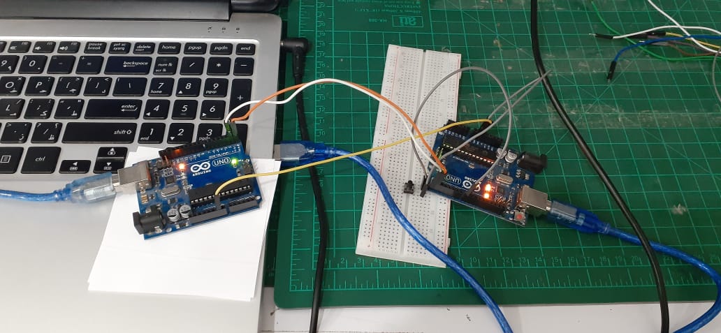
In this assignment we are going to communicate between two devices. The communication is a wired communication utilizing UART on both devices. The devices chosen are two arduino boards, one is connected to a switch and the other is connected to an LED. When the switch is pressed on one device, it sends a message to the other device telling it to switch the LED on and off when the swtich is unpressed.
Here is the setup. Two arduino boards, one connected to a switch and the other is connected to an LED.
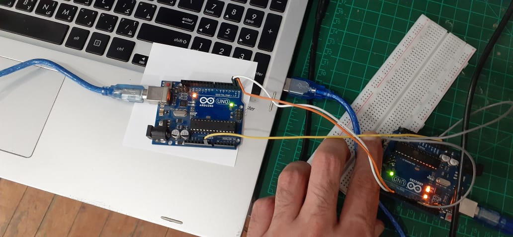
In ActionWhen the button is pressed, the LED is on.
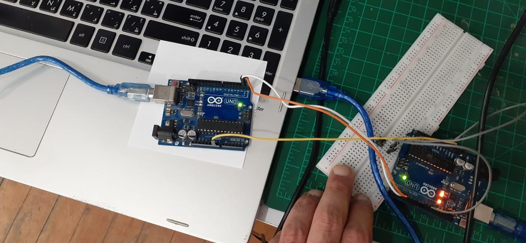
When the button is unpressed, the LED is off.
Inroduction
INTRODUCTION TO UART COMMUNICATION
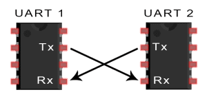
In UART communication, two UARTs communicate directly with each other. The transmitting UART converts parallel data from a controlling device like a CPU into serial form, transmits it in serial to the receiving UART, which then converts the serial data back into parallel data for the receiving device. Only two wires are needed to transmit data between two UARTs. Data flows from the Tx pin of the transmitting UART to the Rx pin of the receiving UART:
UARTs transmit data asynchronously, which means there is no clock signal to synchronize the output of bits from the transmitting UART to the sampling of bits by the receiving UART. Instead of a clock signal, the transmitting UART adds start and stop bits to the data packet being transferred. These bits define the beginning and end of the data packet so the receiving UART knows when to start reading the bits.
When the receiving UART detects a start bit, it starts to read the incoming bits at a specific frequency known as the baud rate. Baud rate is a measure of the speed of data transfer, expressed in bits per second (bps). Both UARTs must operate at about the same baud rate. The baud rate between the transmitting and receiving UARTs can only differ by about 10% before the timing of bits gets too far off.
Both UARTs must also must be configured to transmit and receive the same data packet structure.
HOW UART WORKS
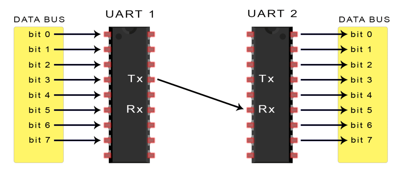
The UART that is going to transmit data receives the data from a data bus. The data bus is used to send data to the UART by another device like a CPU, memory, or microcontroller. Data is transferred from the data bus to the transmitting UART in parallel form. After the transmitting UART gets the parallel data from the data bus, it adds a start bit, a parity bit, and a stop bit, creating the data packet. Next, the data packet is output serially, bit by bit at the Tx pin. The receiving UART reads the data packet bit by bit at its Rx pin. The receiving UART then converts the data back into parallel form and removes the start bit, parity bit, and stop bits. Finally, the receiving UART transfers the data packet in parallel to the data bus on the receiving end:
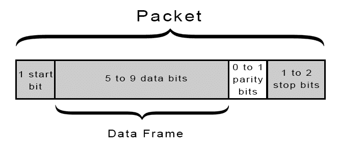
UART transmitted data is organized into packets. Each packet contains 1 start bit, 5 to 9 data bits (depending on the UART), an optional parity bit, and 1 or 2 stop bits:
Planning
So After Reading alot I decided to make the UART Communication So I intend To do is the UART of the Neil's board
So we will Design the PCB Together, and as usual I will leav the Downloads Links Down below
The PCBs are Devided into two Circuits the First one Called the Bridge and the Other Called The Node
What we will Design now is the Bridge Circuit
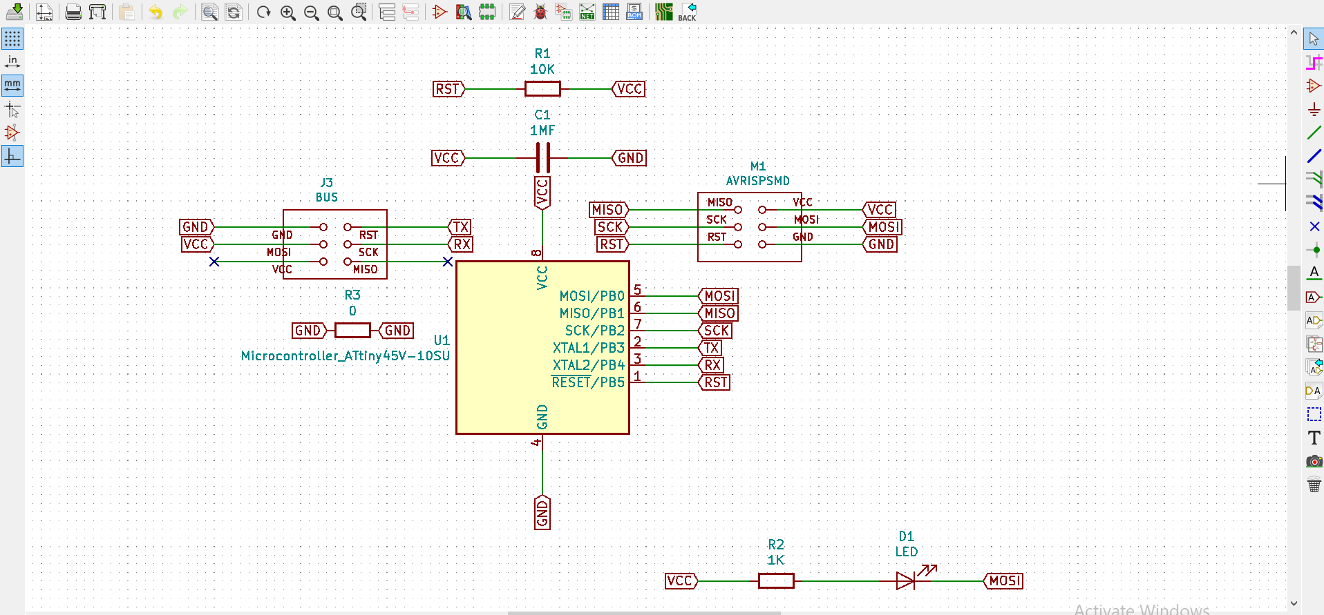
But First We Need to know the List of Components
Res 1206
SPI
ATTINY45
SPI
FTDI
LED
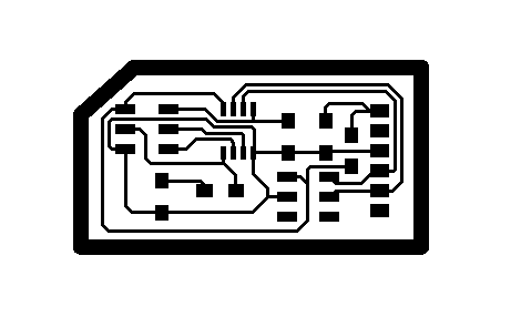
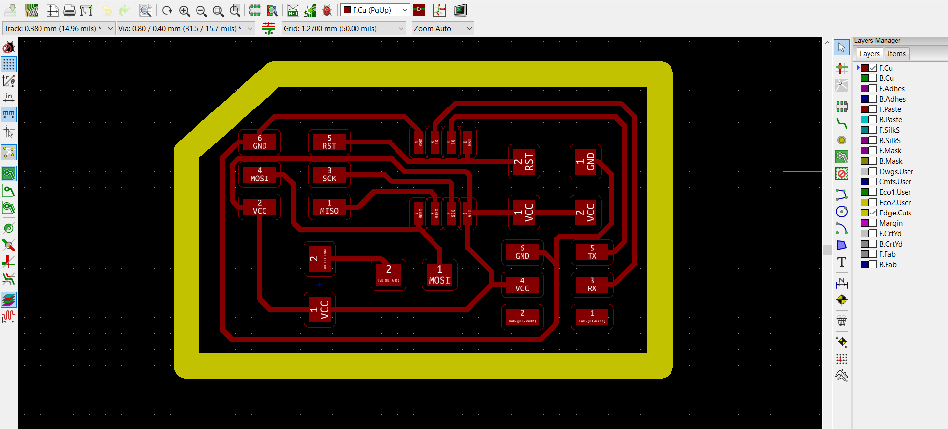
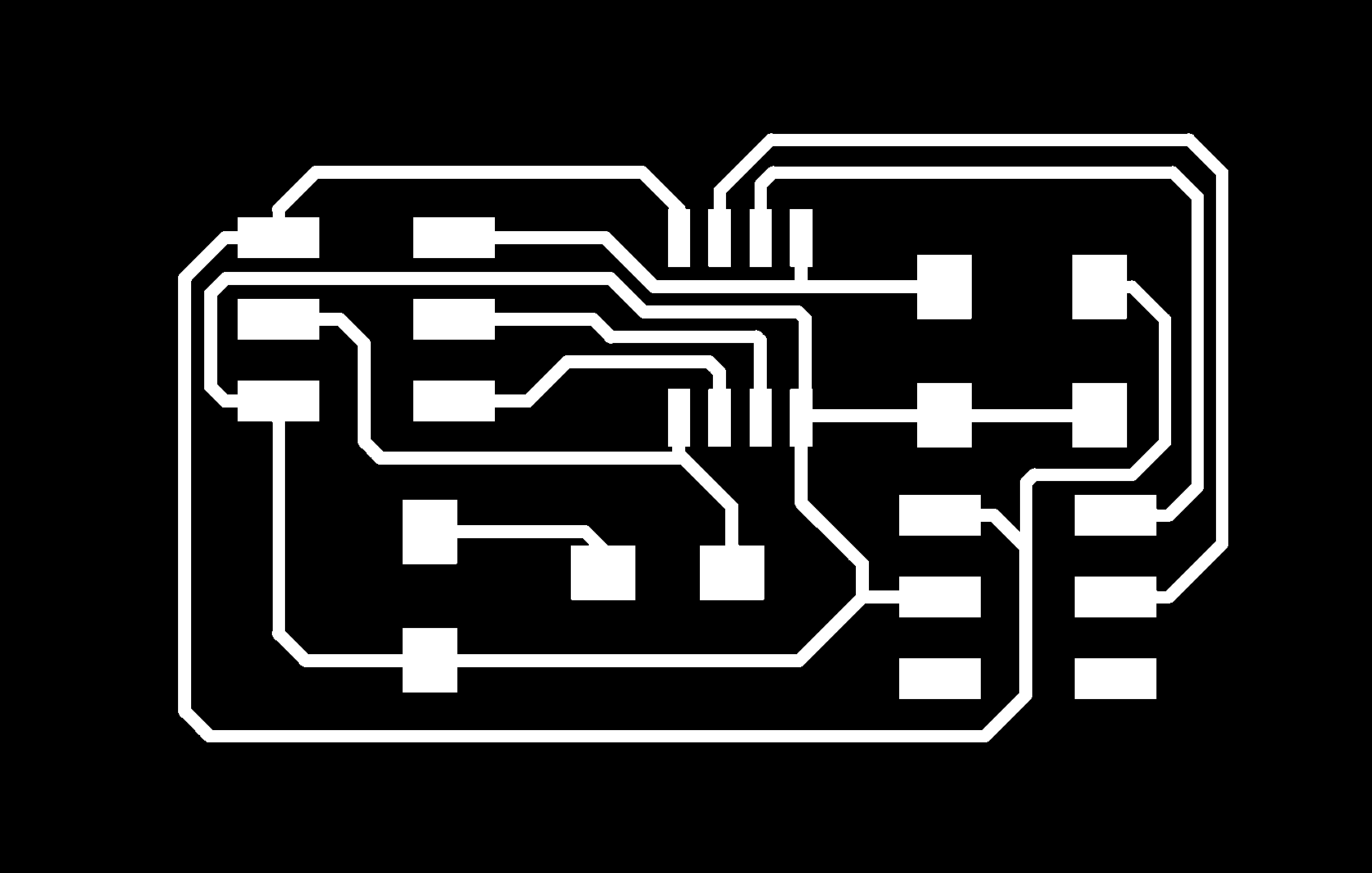
And as we know we need to make the Traces (board), and don't forget to Export the Board as Png
And then Let's move on to design the nodes PCBs
For nodes we will Fabricate two of them
You need To add the following Components when you design
Capacitor 1206
ATTINY 45
2 ISP
Resistor 1206
LED
And here is the Png Files
and As you know After that Part we Will Fabricate the PCB using the modela but I will Skip this part because we Go throw it alot
Testing
So now Go and Fabricate the PCB and Start To Solder the Components
The Results should be Something like that
| Component | Description | QTY |
|---|---|---|
| ATTINY45 | IC AVR MCU 4K 10MHZ 8SOIC- | 3 |
| 609-5161-1-ND | 6 Positions Header Connector 0.100" SMD | 6 |
| 311-10.0KFRCT-ND | RES 10.0K OHM 1-4W 1% 1206 SMD | 3 |
| 311-499FRCT-ND | RES 499 OHM 1-4W 1% 1206 SMD | 3 |
| 311-0FRCT-ND | RES 0 OHM 1-4W 1% 1206 SMD | 1 |
| 445-1423-1-ND | CAP CER 1UF 50V X7R 10% 1206- | 3 |
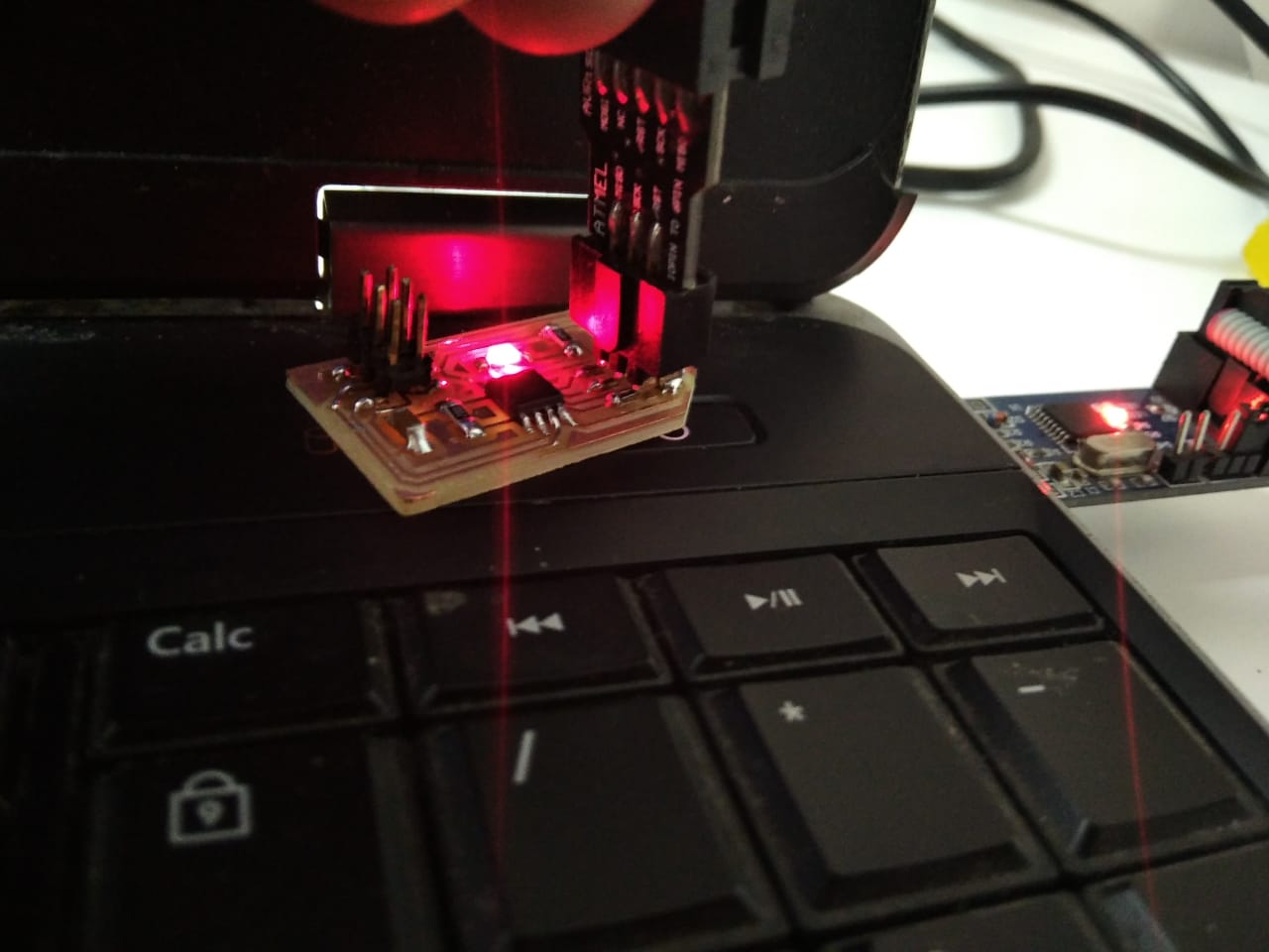
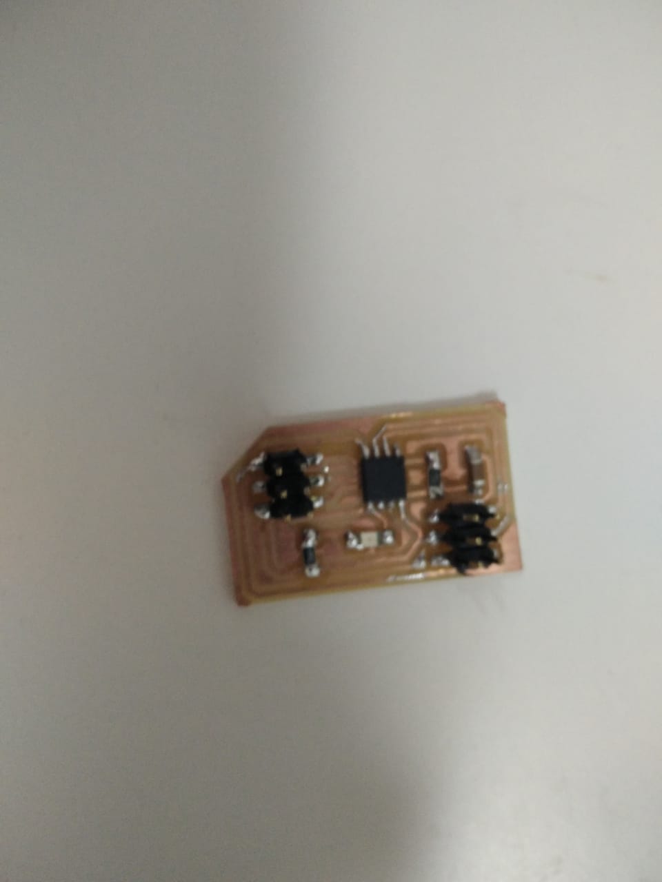
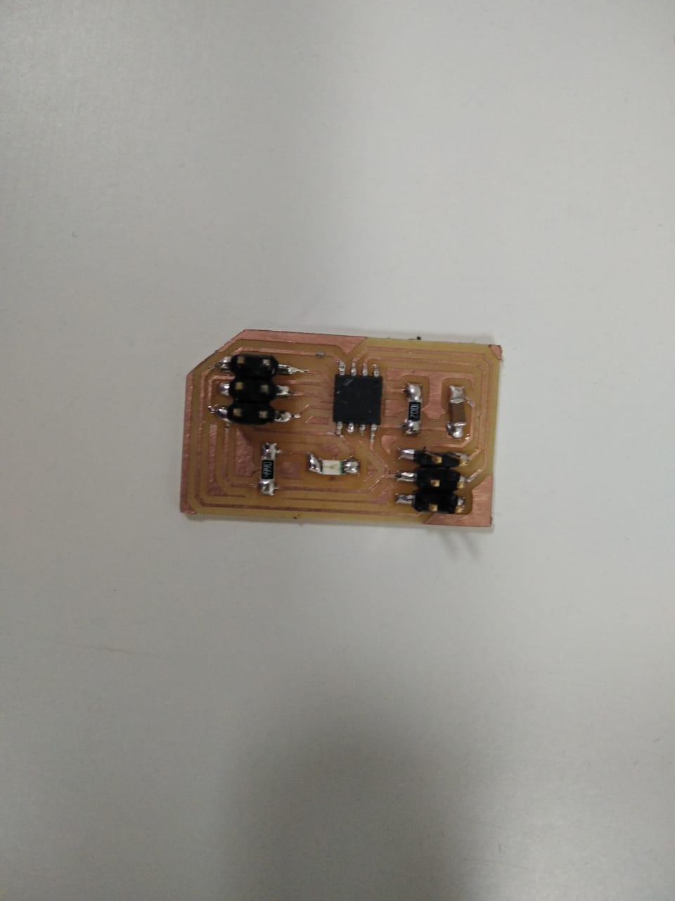
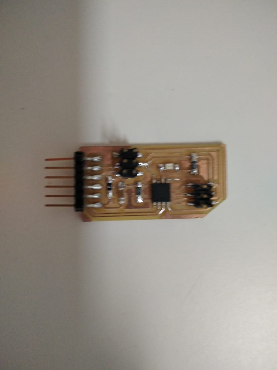
That's the Photos of the PCBs after Soldering
that's the Node PCB
that's the Bridge PCB
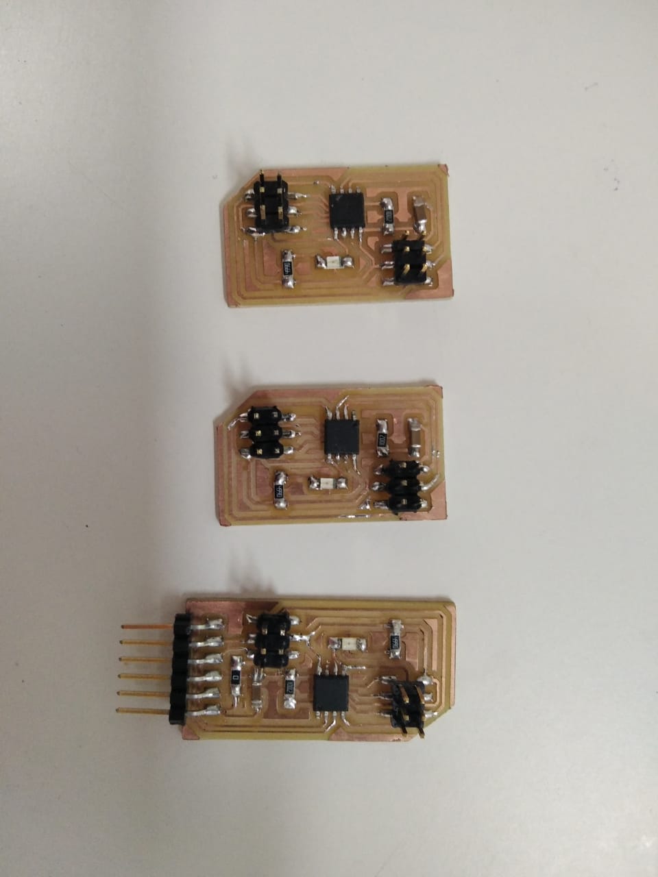
and here is the three PCBs ( what we need to make the UART Connection)
then Bring the Wires to make the Connection
Note: Make sure that you put the wires in the right place because other wise it wouldn't work
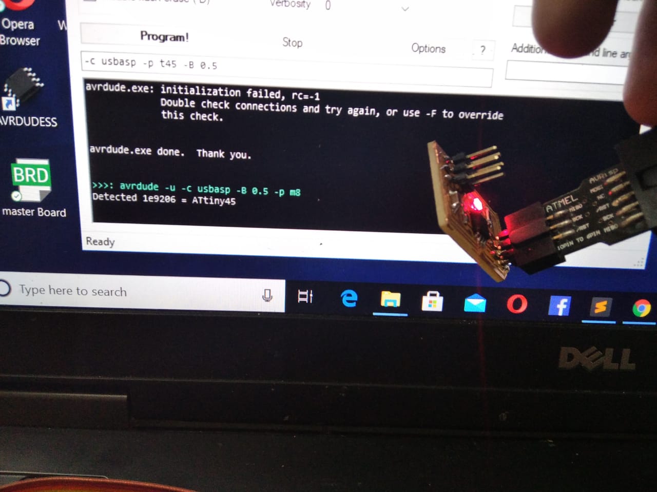
Put the Usbasp
and then Bring the Code that we will Upload in Every PCB
Note: the Code that I used is from Neil's Code, So I will Left the Code down below
                                //
//
// hello.bus.45.c
//
// 9600 baud serial bus hello-world
//
// Neil Gershenfeld
// 11/24/10
//
// (c) Massachusetts Institute of Technology 2010
// Permission granted for experimental and personal use;
// license for commercial sale available from MIT.
//

#include
#include
#include
#include

#define output(directions,pin) (directions |= pin) // set port direction for output
#define input(directions,pin) (directions &= (~pin)) // set port direction for input
#define set(port,pin) (port |= pin) // set port pin
#define clear(port,pin) (port &= (~pin)) // clear port pin
#define pin_test(pins,pin) (pins & pin) // test for port pin
#define bit_test(byte,bit) (byte & (1 << bit)) // test for bit set
#define bit_delay_time 100 // bit delay for 9600 with overhead
#define bit_delay() _delay_us(bit_delay_time) // RS232 bit delay
#define half_bit_delay() _delay_us(bit_delay_time/2) // RS232 half bit delay
#define led_delay() _delay_ms(100) // LED flash delay

#define led_port PORTB
#define led_direction DDRB
#define led_pin (1 << PB0)

#define serial_port PORTB
#define serial_direction DDRB
#define serial_pins PINB
#define serial_pin_in (1 << PB3)
#define serial_pin_out (1 << PB4)

#define node_id '0'

void get_char(volatile unsigned char *pins, unsigned char pin, char *rxbyte) {
   //
   // read character into rxbyte on pins pin
   //    assumes line driver (inverts bits)
   //
   *rxbyte = 0;
   while (pin_test(*pins,pin))
      //
      // wait for start bit
      //
      ;
   //
   // delay to middle of first data bit
   //
   half_bit_delay();
   bit_delay();
   //
   // unrolled loop to read data bits
   //
   if pin_test(*pins,pin)
      *rxbyte |= (1 << 0);
   else
      *rxbyte |= (0 << 0);
   bit_delay();
   if pin_test(*pins,pin)
      *rxbyte |= (1 << 1);
   else
      *rxbyte |= (0 << 1);
   bit_delay();
   if pin_test(*pins,pin)
      *rxbyte |= (1 << 2);
   else
      *rxbyte |= (0 << 2);
   bit_delay();
   if pin_test(*pins,pin)
      *rxbyte |= (1 << 3);
   else
      *rxbyte |= (0 << 3);
   bit_delay();
   if pin_test(*pins,pin)
      *rxbyte |= (1 << 4);
   else
      *rxbyte |= (0 << 4);
   bit_delay();
   if pin_test(*pins,pin)
      *rxbyte |= (1 << 5);
   else
      *rxbyte |= (0 << 5);
   bit_delay();
   if pin_test(*pins,pin)
      *rxbyte |= (1 << 6);
   else
      *rxbyte |= (0 << 6);
   bit_delay();
   if pin_test(*pins,pin)
      *rxbyte |= (1 << 7);
   else
      *rxbyte |= (0 << 7);
   //
   // wait for stop bit
   //
   bit_delay();
   half_bit_delay();
   }

void put_char(volatile unsigned char *port, unsigned char pin, char txchar) {
   //
   // send character in txchar on port pin
   //    assumes line driver (inverts bits)
   //
   // start bit
   //
   clear(*port,pin);
   bit_delay();
   //
   // unrolled loop to write data bits
   //
   if bit_test(txchar,0)
      set(*port,pin);
   else
      clear(*port,pin);
   bit_delay();
   if bit_test(txchar,1)
      set(*port,pin);
   else
      clear(*port,pin);
   bit_delay();
   if bit_test(txchar,2)
      set(*port,pin);
   else
      clear(*port,pin);
   bit_delay();
   if bit_test(txchar,3)
      set(*port,pin);
   else
      clear(*port,pin);
   bit_delay();
   if bit_test(txchar,4)
      set(*port,pin);
   else
      clear(*port,pin);
   bit_delay();
   if bit_test(txchar,5)
      set(*port,pin);
   else
      clear(*port,pin);
   bit_delay();
   if bit_test(txchar,6)
      set(*port,pin);
   else
      clear(*port,pin);
   bit_delay();
   if bit_test(txchar,7)
      set(*port,pin);
   else
      clear(*port,pin);
   bit_delay();
   //
   // stop bit
   //
   set(*port,pin);
   bit_delay();
   //
   // char delay
   //
   bit_delay();
   }

void put_string(volatile unsigned char *port, unsigned char pin, PGM_P str) {
   //
   // send character in txchar on port pin
   //    assumes line driver (inverts bits)
   //
   static char chr;
   static int index;
   index = 0;
   do {
      chr = pgm_read_byte(&(str[index]));
      put_char(&serial_port, serial_pin_out, chr);
      ++index;
      } while (chr != 0);
   }

void flash() {
   //
   // LED flash delay
   //
   clear(led_port, led_pin);
   led_delay();
   set(led_port, led_pin);
   }

int main(void) {
   //
   // main
   //
   static char chr;
   //
   // set clock divider to /1
   //
   CLKPR = (1 << CLKPCE);
   CLKPR = (0 << CLKPS3) | (0 << CLKPS2) | (0 << CLKPS1) | (0 << CLKPS0);
   //
   // initialize output pins
   //
   set(serial_port, serial_pin_out);
   input(serial_direction, serial_pin_out);
   set(led_port, led_pin);
   output(led_direction, led_pin);
   //
   // main loop
   //
   while (1) {
      get_char(&serial_pins, serial_pin_in, &chr);
      flash();
      if (chr == node_id) {
         output(serial_direction, serial_pin_out);
         static const char message[] PROGMEM = "node ";
         put_string(&serial_port, serial_pin_out, (PGM_P) message);
         put_char(&serial_port, serial_pin_out, chr);
         put_char(&serial_port, serial_pin_out, 10); // new line
         led_delay();
         flash();
         input(serial_direction, serial_pin_out);
         }
      }
   }
And then Upload the Code on the PCB's
And here is the moment of truth
Downloads
