- Group Assignment:
- Characterize your lasercutter's focus, power, speed, rate, kerf, and joint clearance
- Individual Assignment:
- Cut something on the vinylcutter
- Design, lasercut, and document a parametric construction kit,
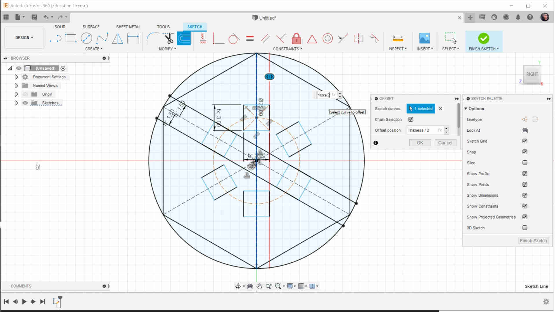
accounting for the lasercutter kerf,
which can be assembled in multiple ways,
and for extra credit include elements that aren't flat
- Link to the group assignment page
- Explaine how I parametrically designed my files
- Document how I made my press-fit kit
- Document how I made my vinyl cutting
- Include my original design files
- Include my hero shots
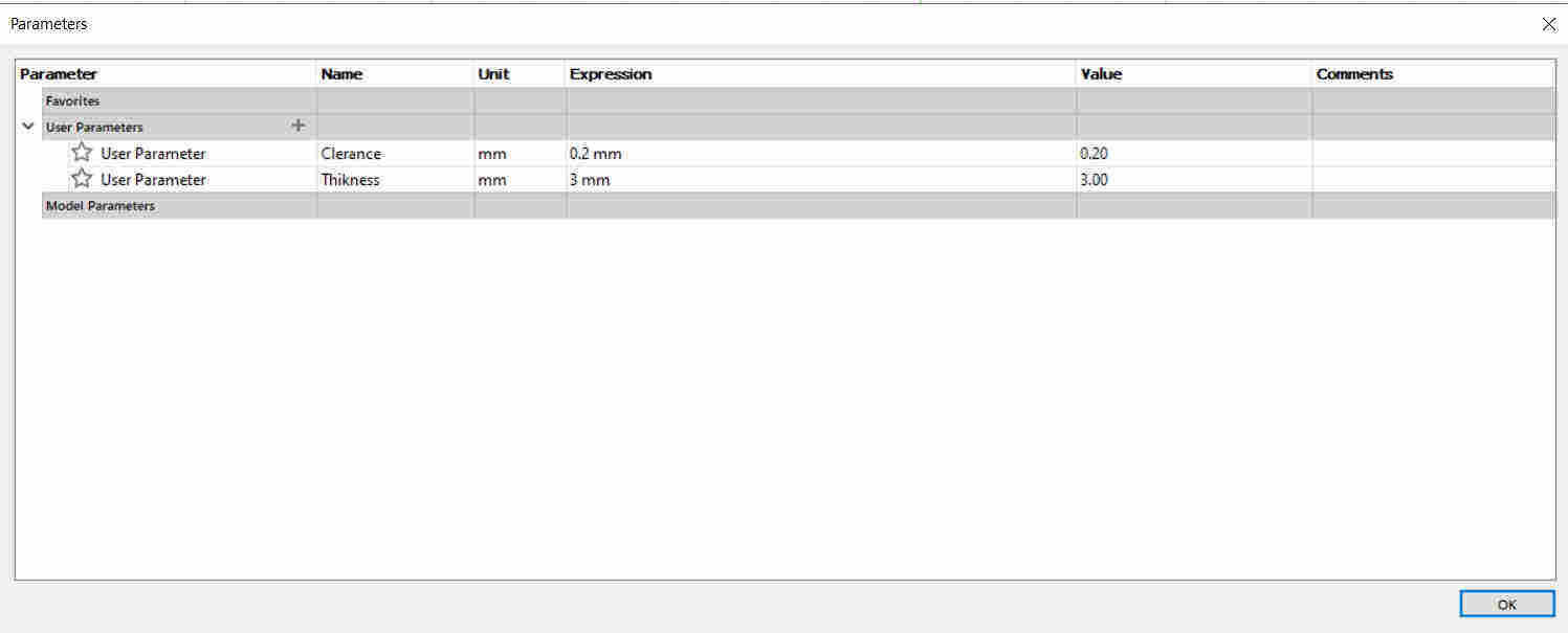
- Thikcness
- Cleaerance

Fusion360 CutStudio LaserWork CorelDRAW Morn:MT3050D Roland:GX-24
Group Assignment
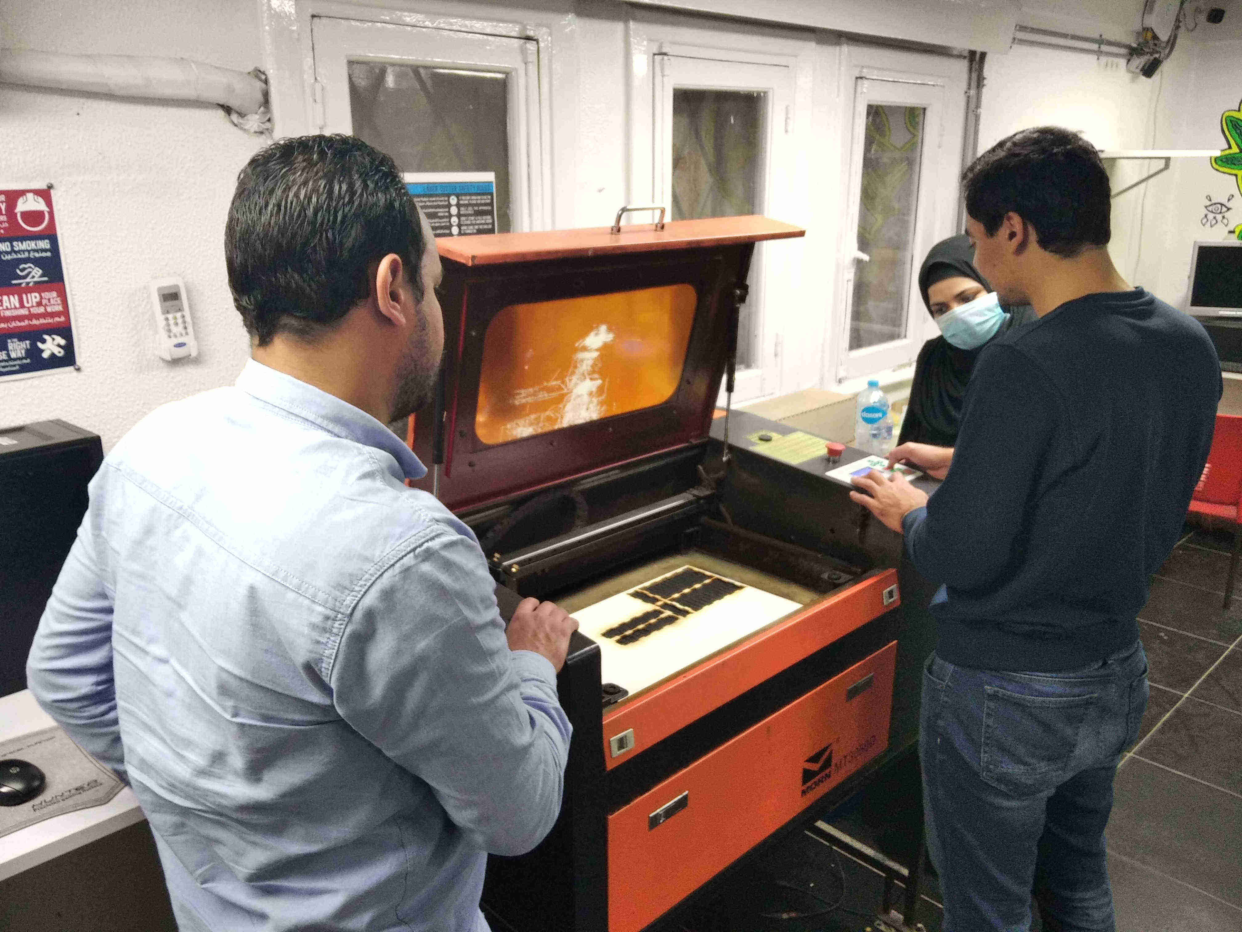
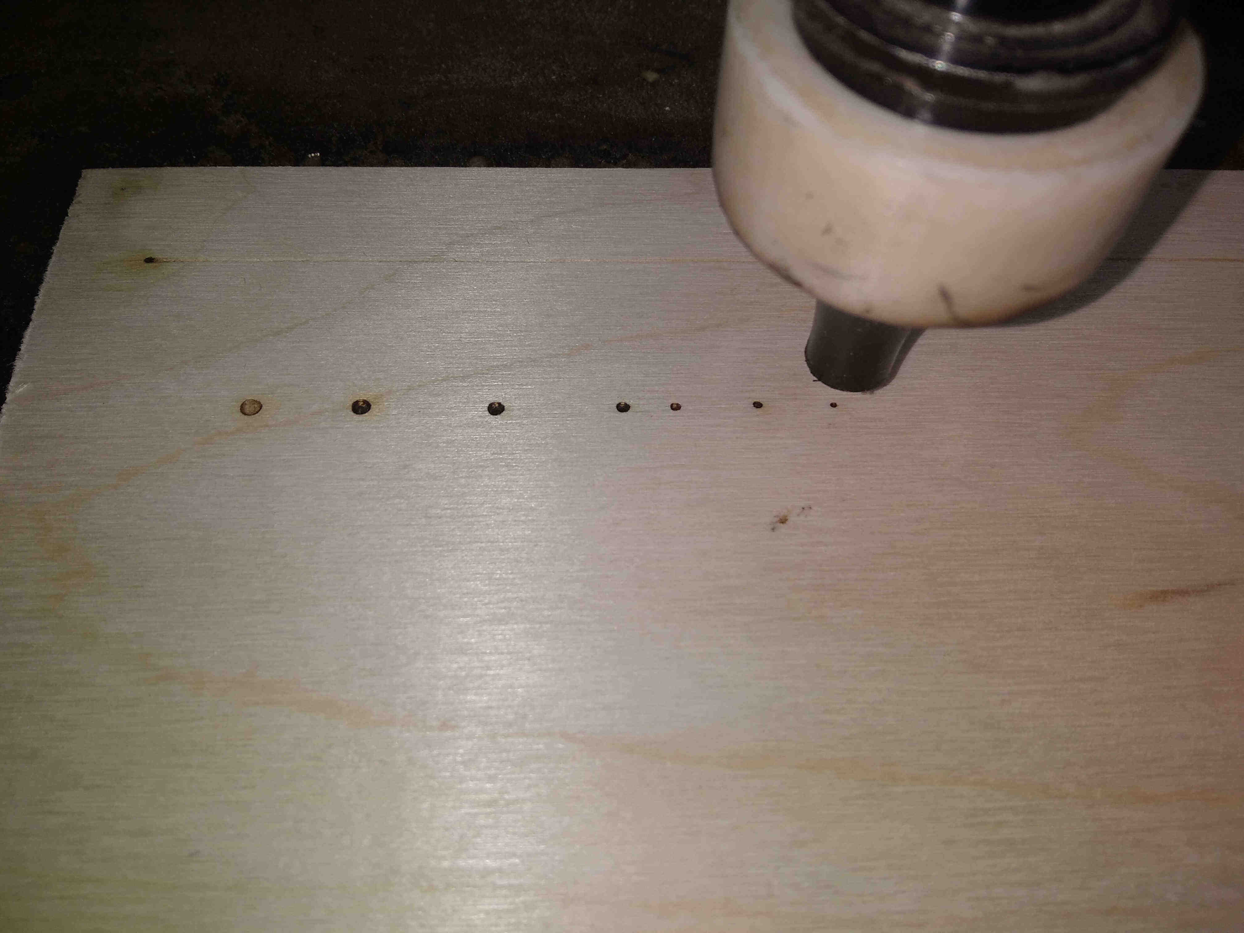
Measuring the focus
We started by measuring the focus of the machine. The focus is the smallest dot the laser makes, so we leveled the bed up and down until we reached the smallest dot then we measured the distance between the nozzle and the material which is around 6 mm.
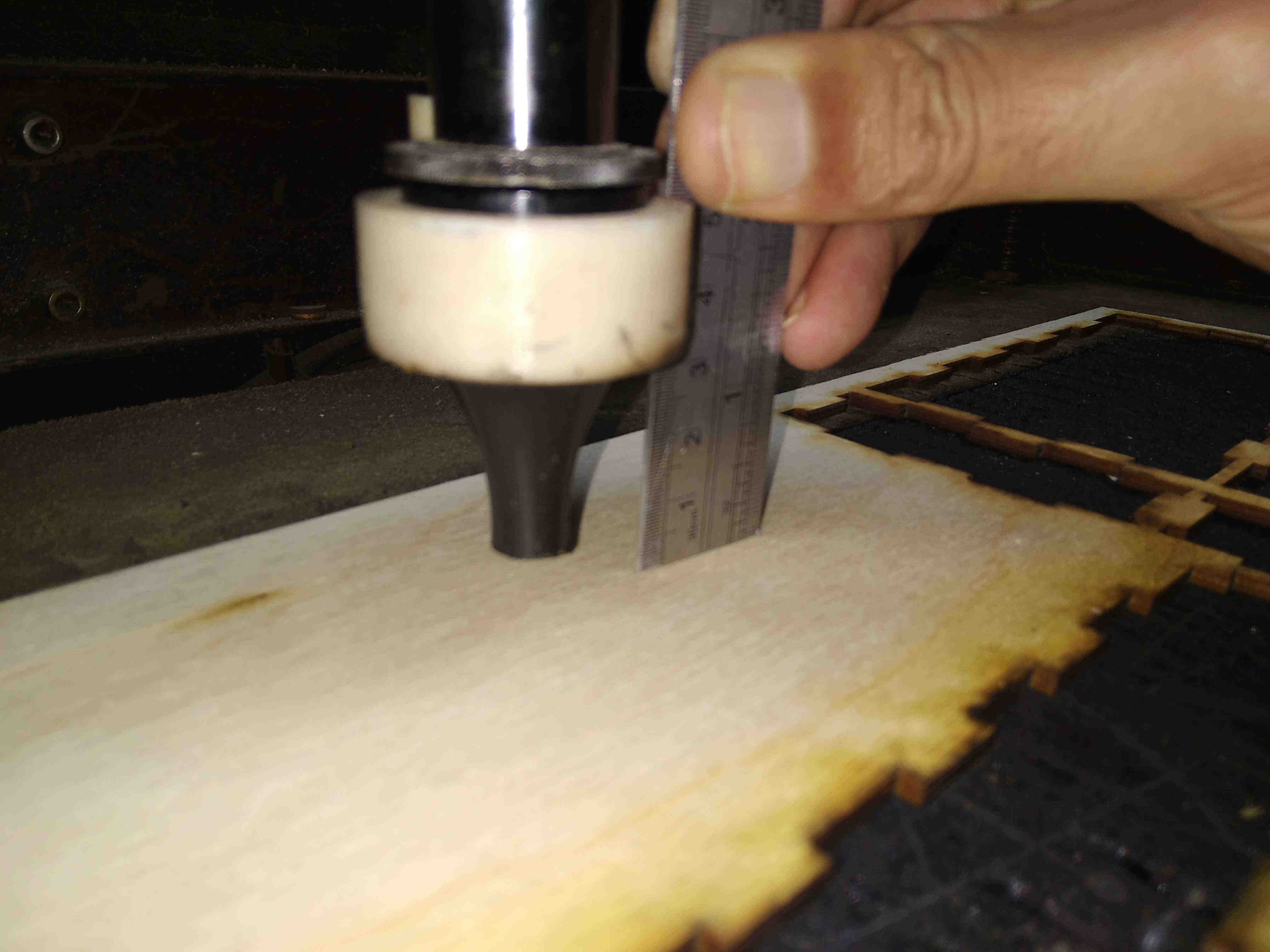
Kerf and clearance measurement
To measure the kerf and the clearance, we designed a comb part that has slots with width varying from 2.8 -> 3.2

We cut the part on the laser cutter using the proper cutting settings above and tried to fit the comb together. the comb fitted a hard fit in the 2.8 slot, however fit a proper fit in the 2.9 slot. we approximated the kerf to be between 0.1 mm and 0.2 mm. To measure the kerf we substract the slot width from the material thickness
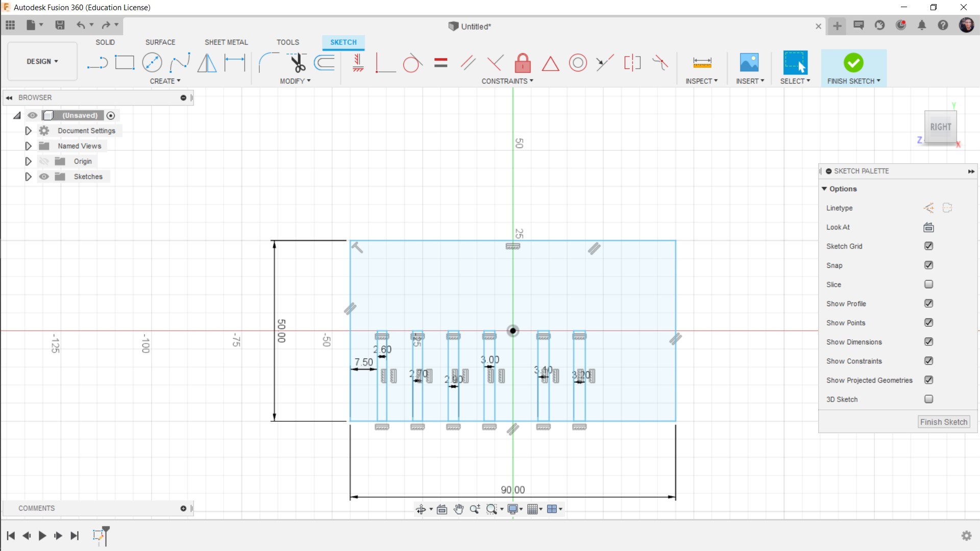
Parametric Kit
Parameter(n): a numerical or other measurable factor forming one of a set that defines a system or sets the conditions of its operation.
I wondered a little about the meaning of Parametric Design, and I found this answer very helpful.
Generally speaking, the variables of my construction kit designs can be:
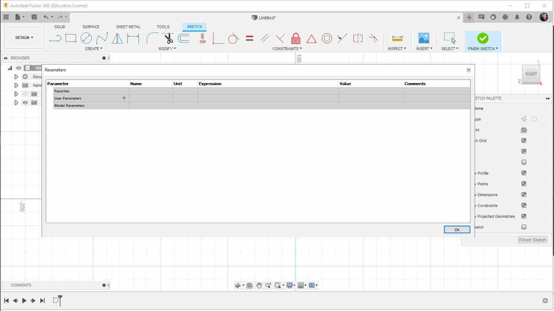
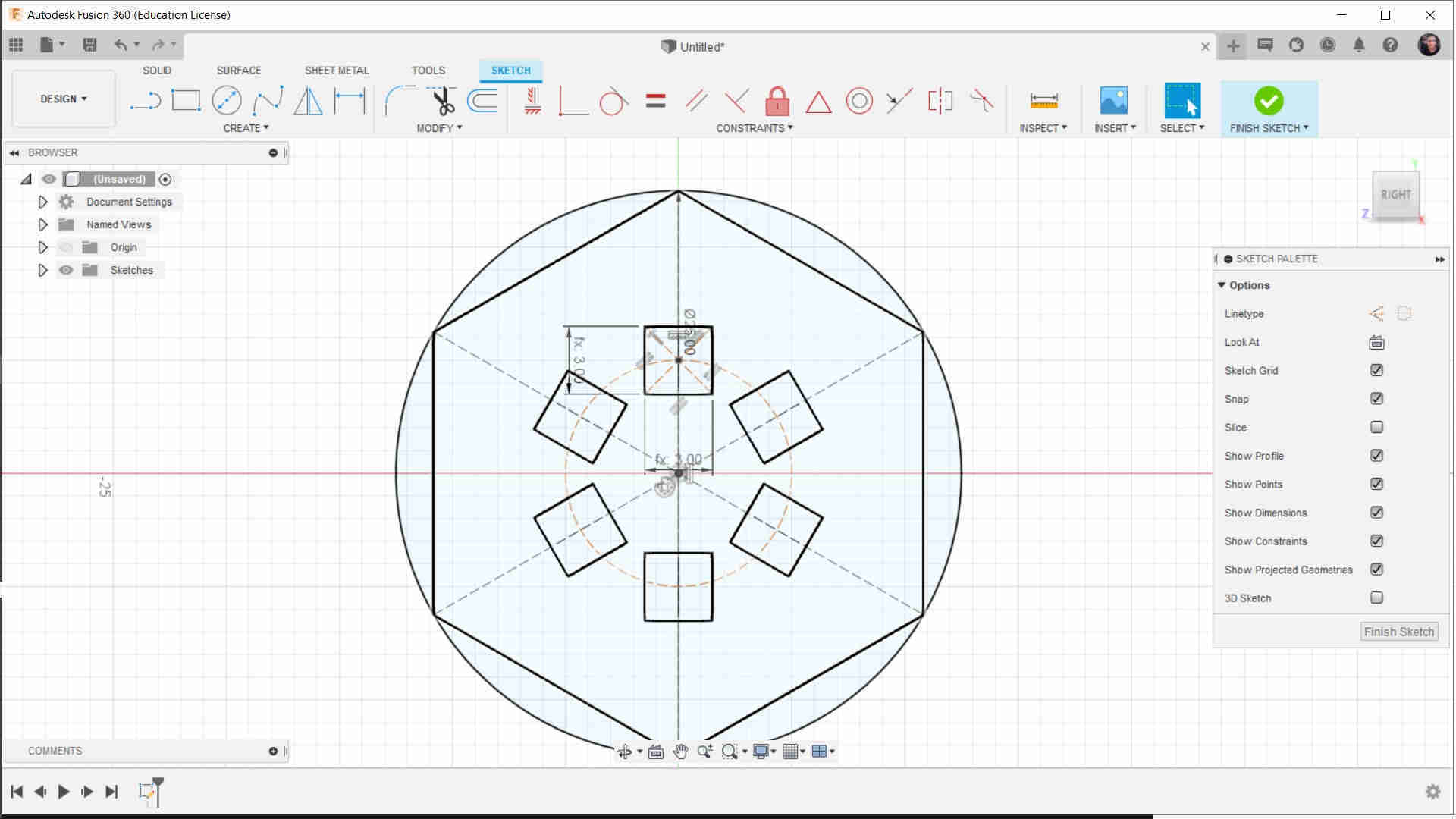
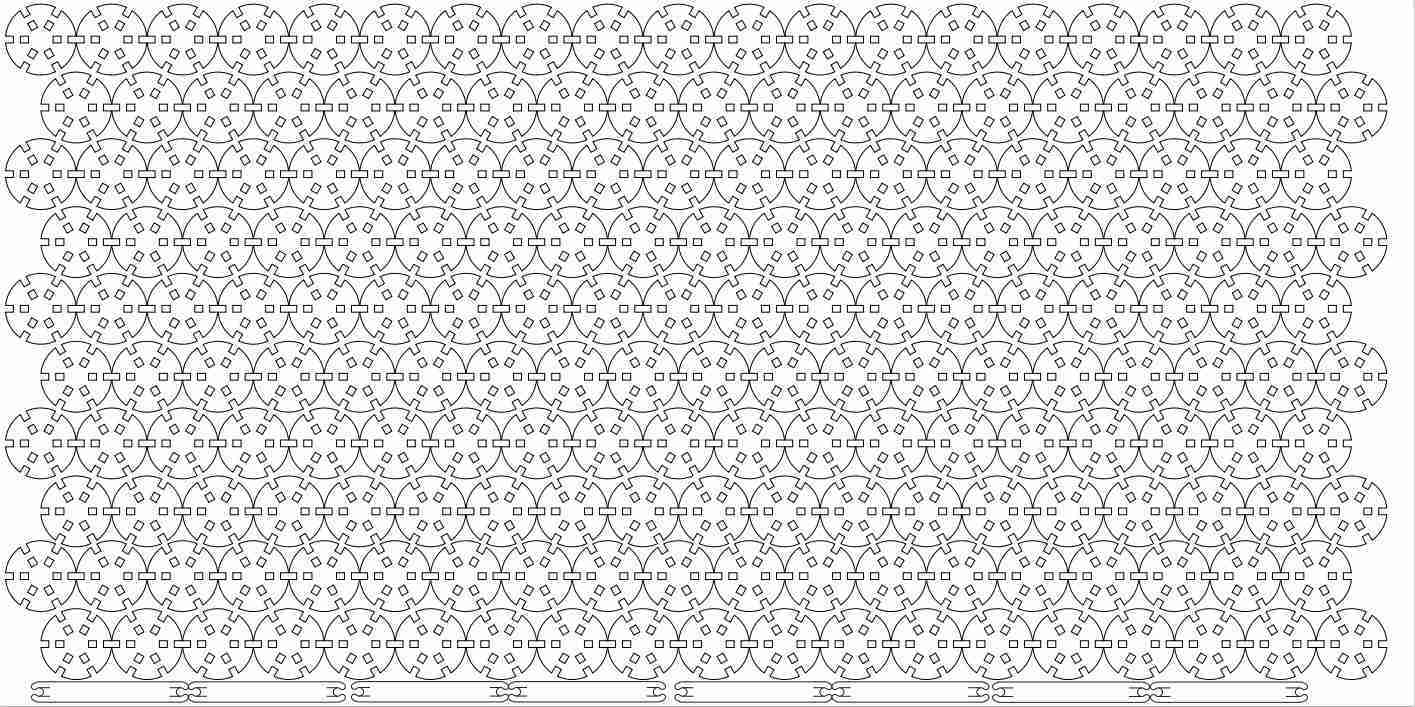
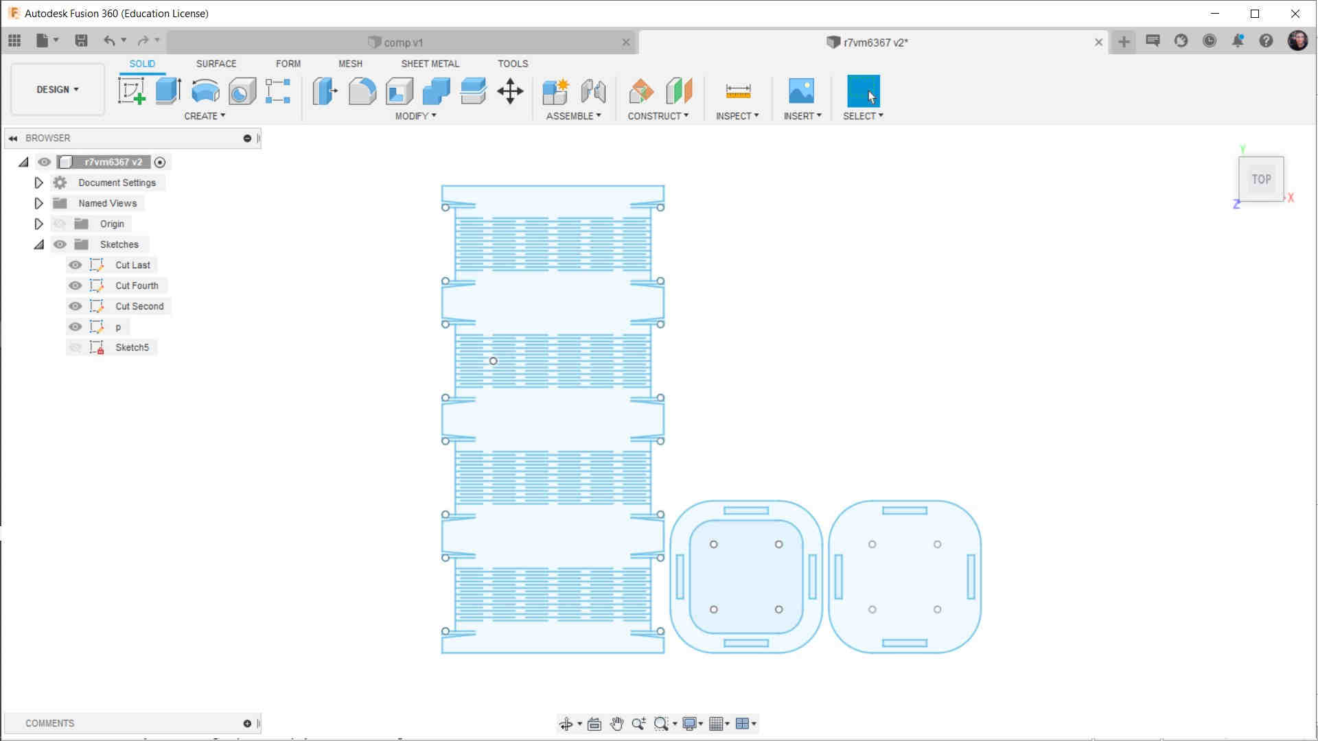
I built a Fusion360 sketch and defined my parameters as follows:
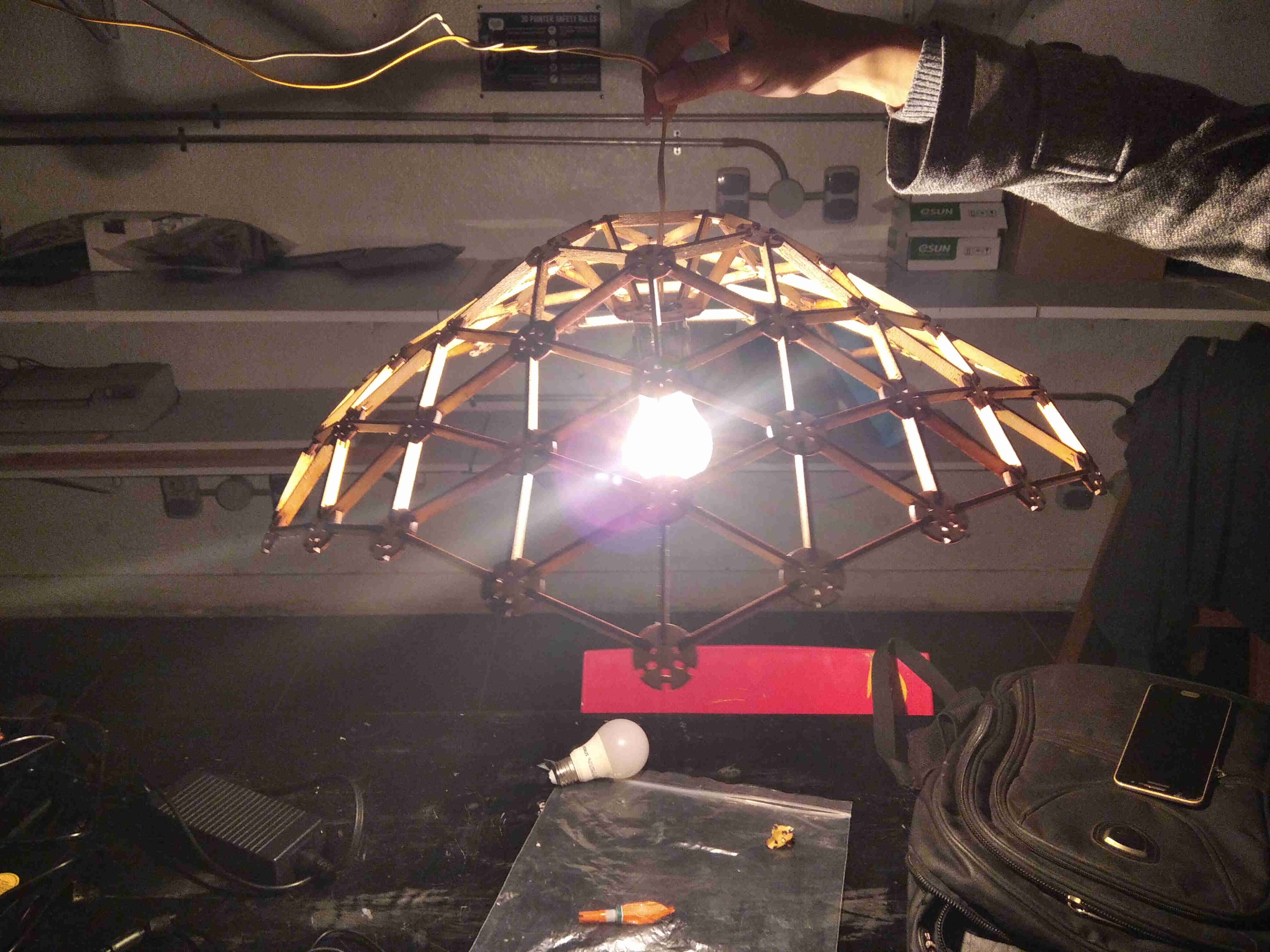
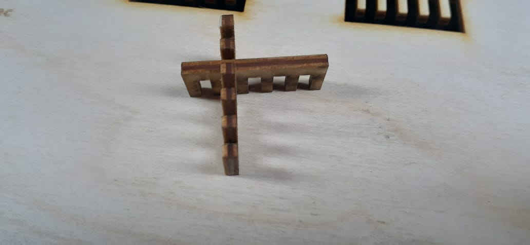
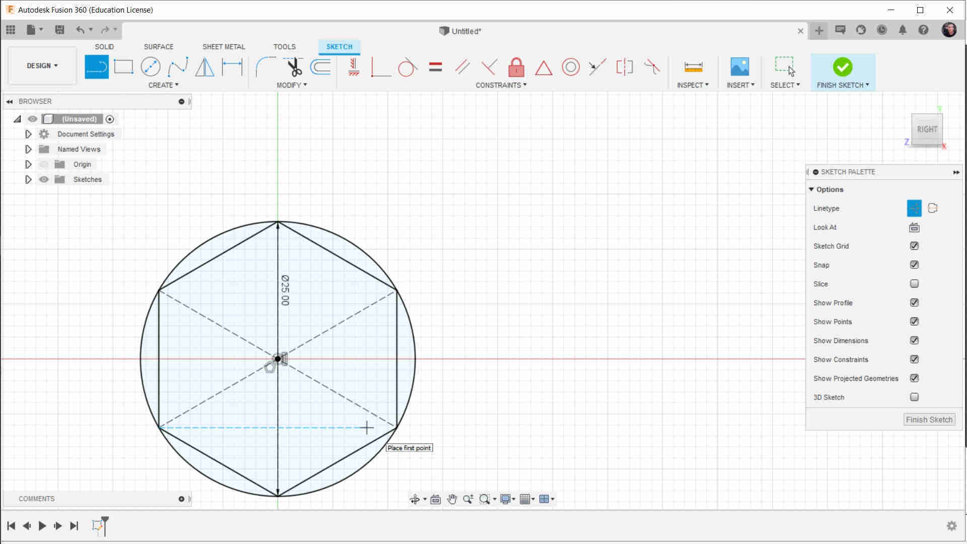
Then I start to Draw my Basic Shape (I Will call It SIP)
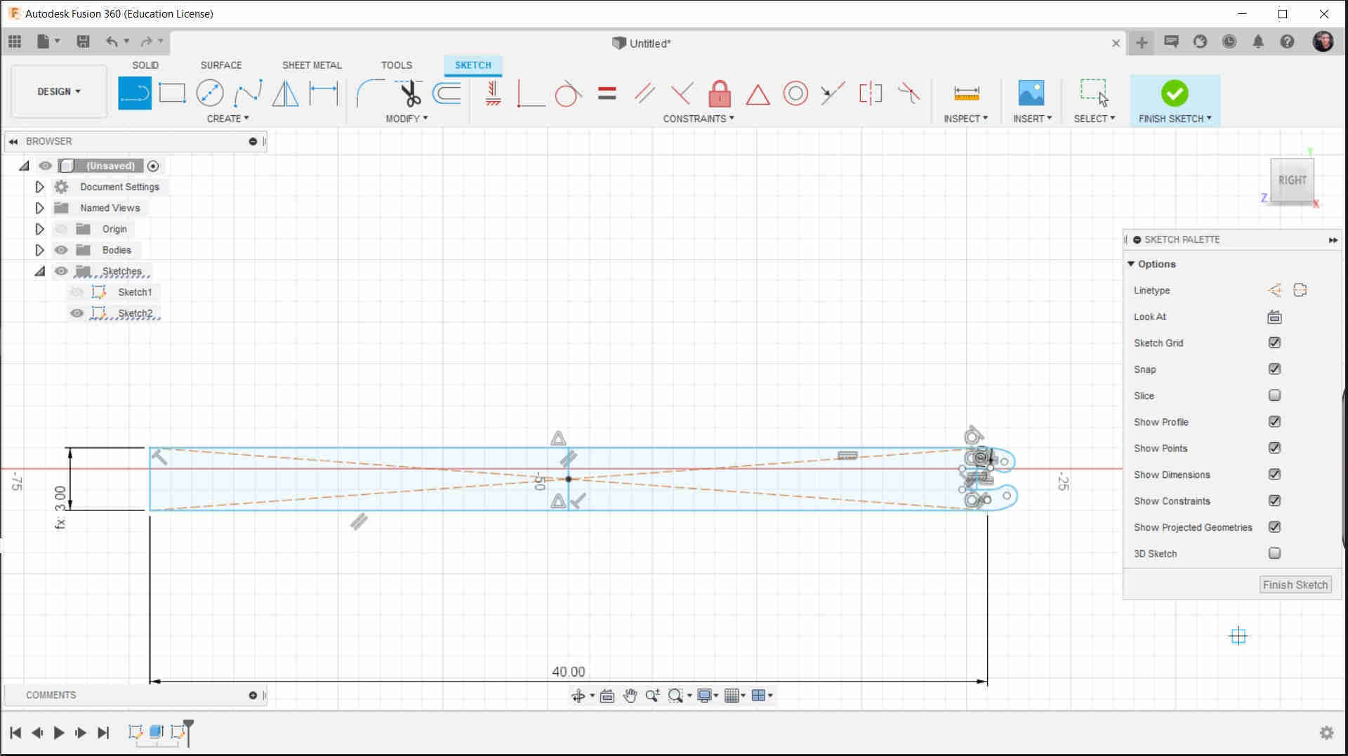
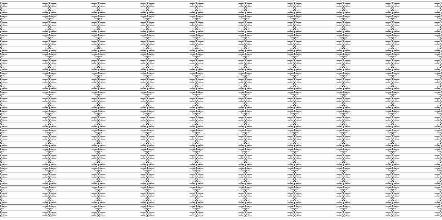
Then I start to make the Stick

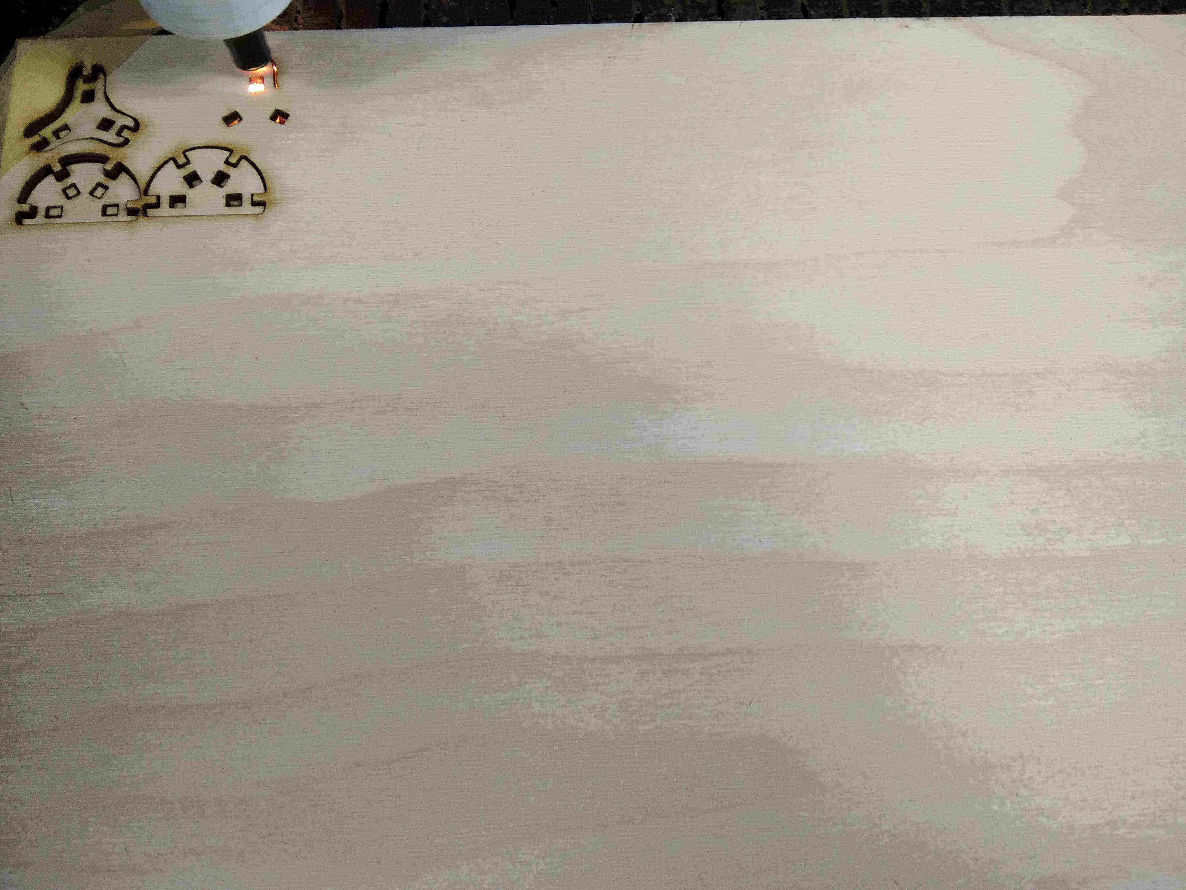
Then I Put the Files Into the LASER Cutter
Note
For our Laser Cutter The Power of the Laser was 60 watt
So The Speed and Power I will choose Is depend on the Power of the tube of the laser
For PlyWood 3mm :
Cutting : Speed (25mm/s)---Power (Min:65%---Max:65%)
For PlyWood 6mm :
Cutting : Speed (15mm/s)---Power (Min:75%---Max:75%)
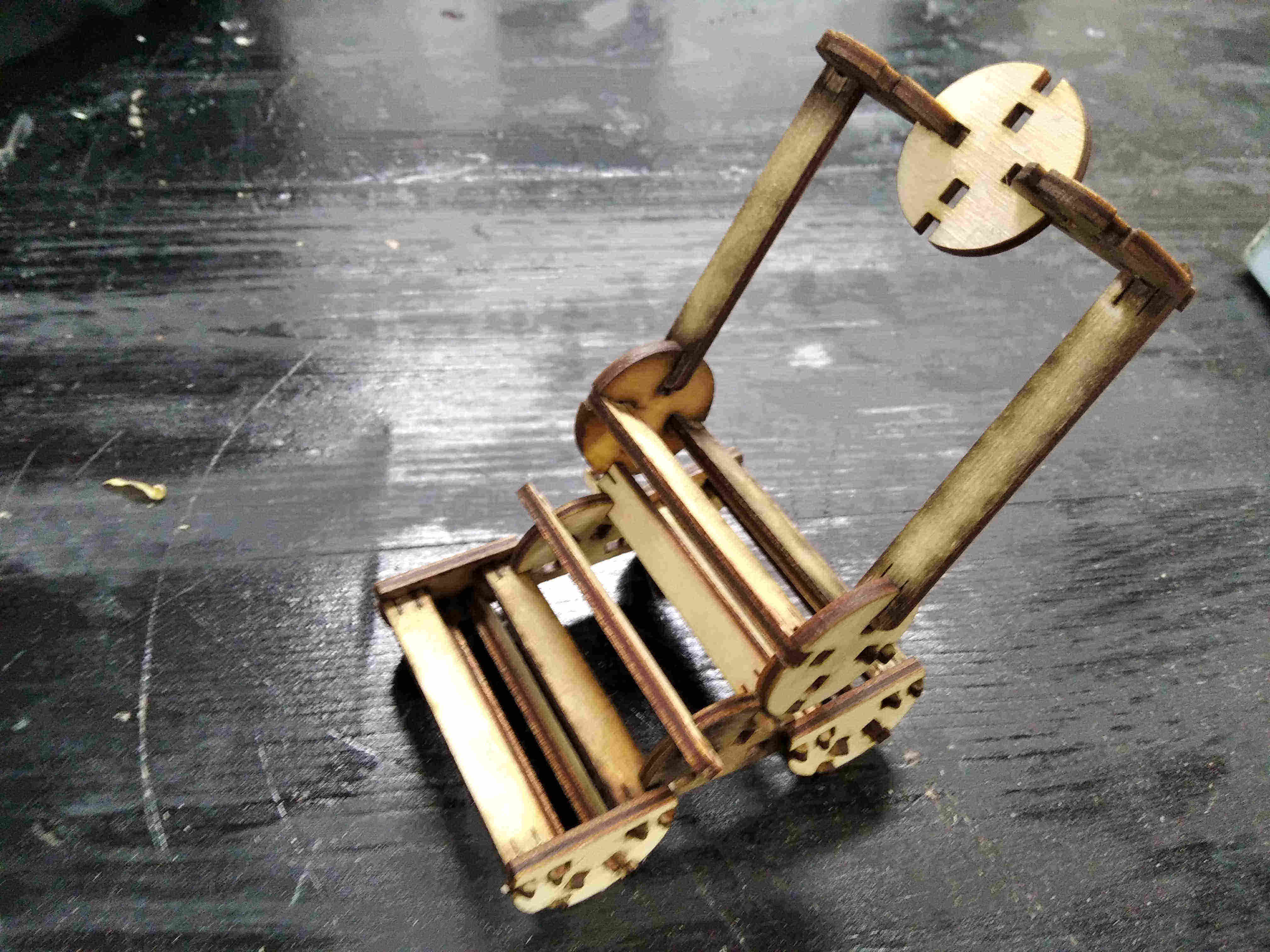
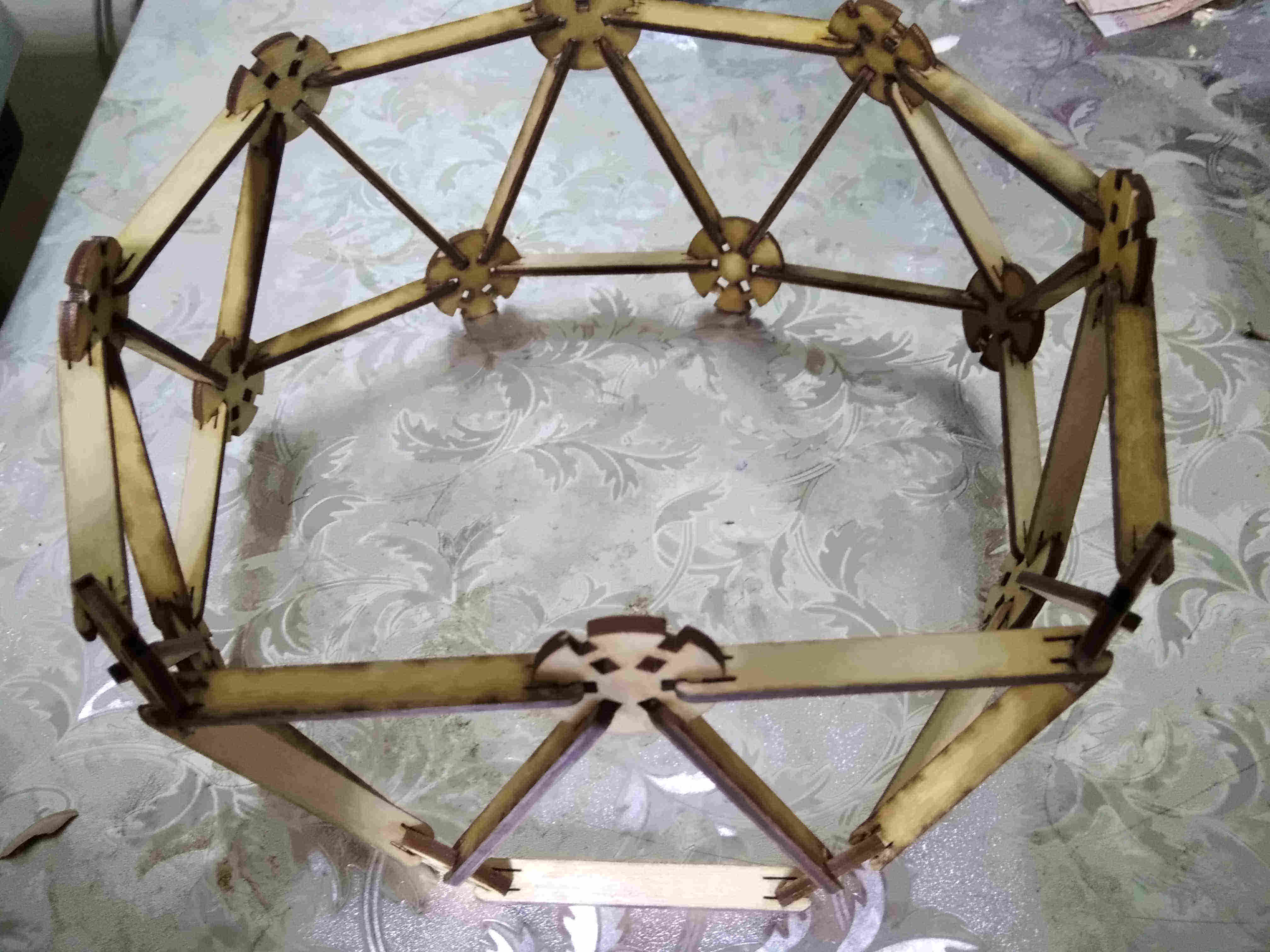
Then we Grap them From the Laser
and we Can Make Wonderful things With These Parts
Vainal Cutter
it was easy and interesting task to work on vainel cutter
I open CutStudio
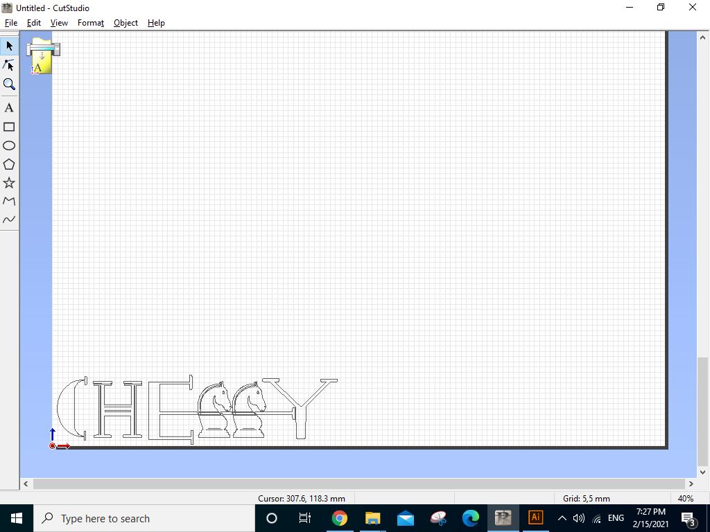
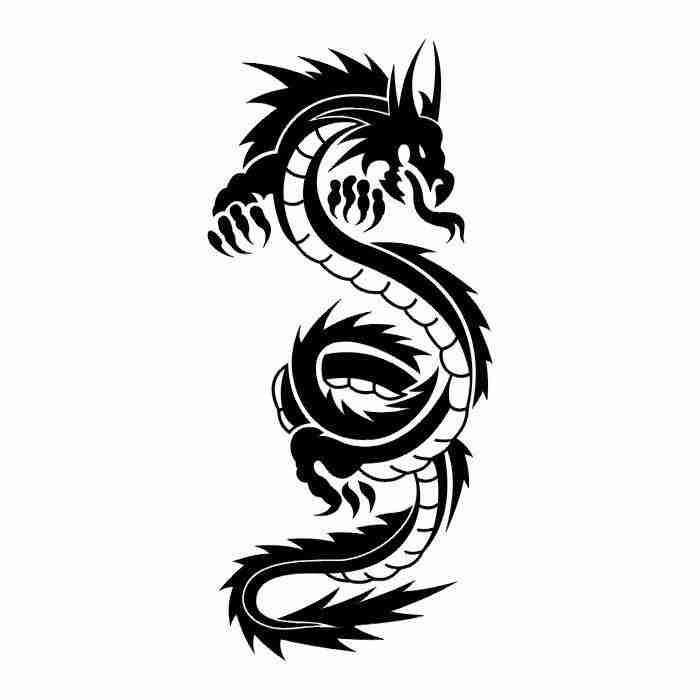
Then I insert The Thing I want to Cut (in my case I want to make my logo)
I Modify the Force of Cutting and Put my Role in the Machine
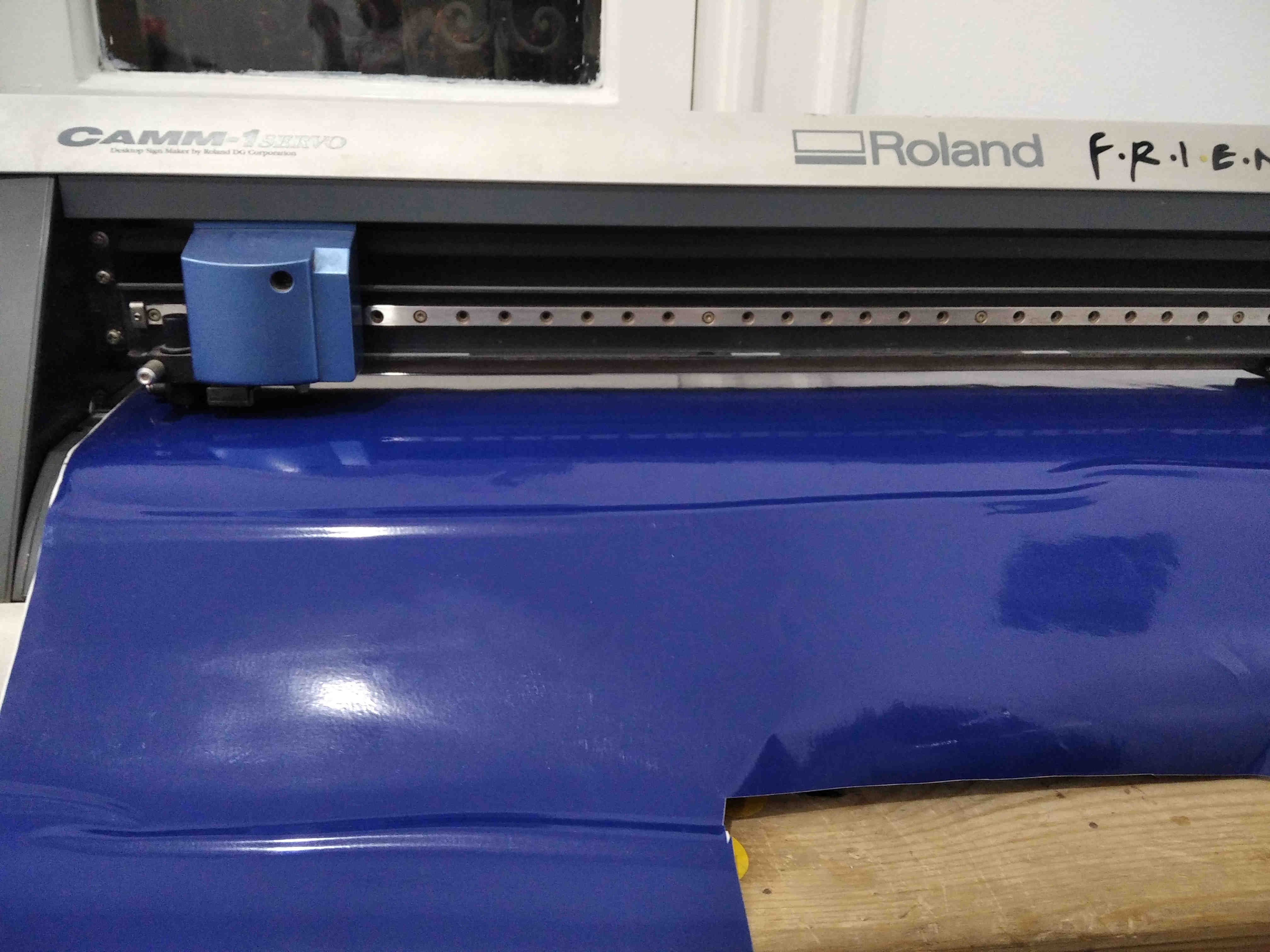
and here is the Result
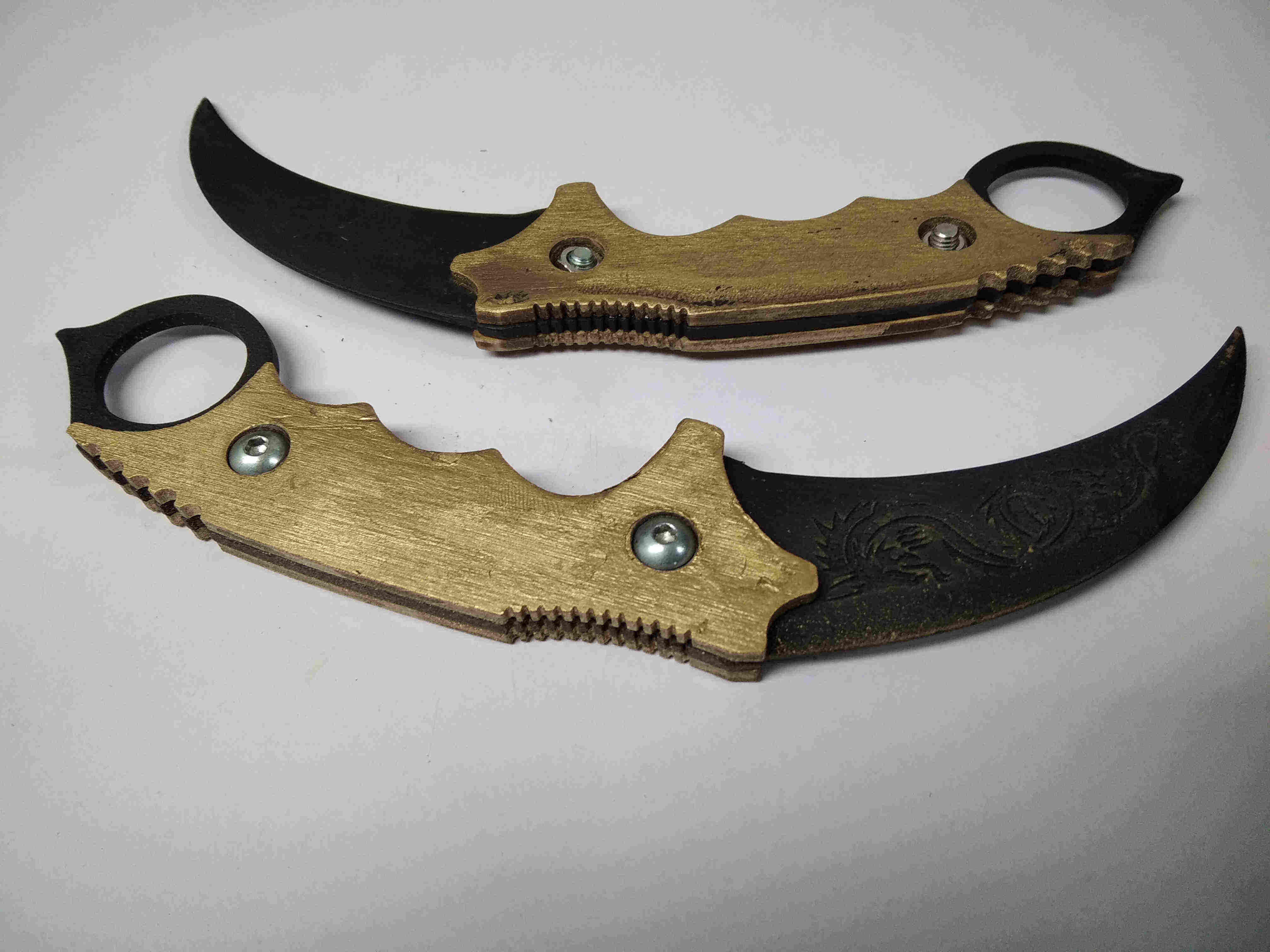
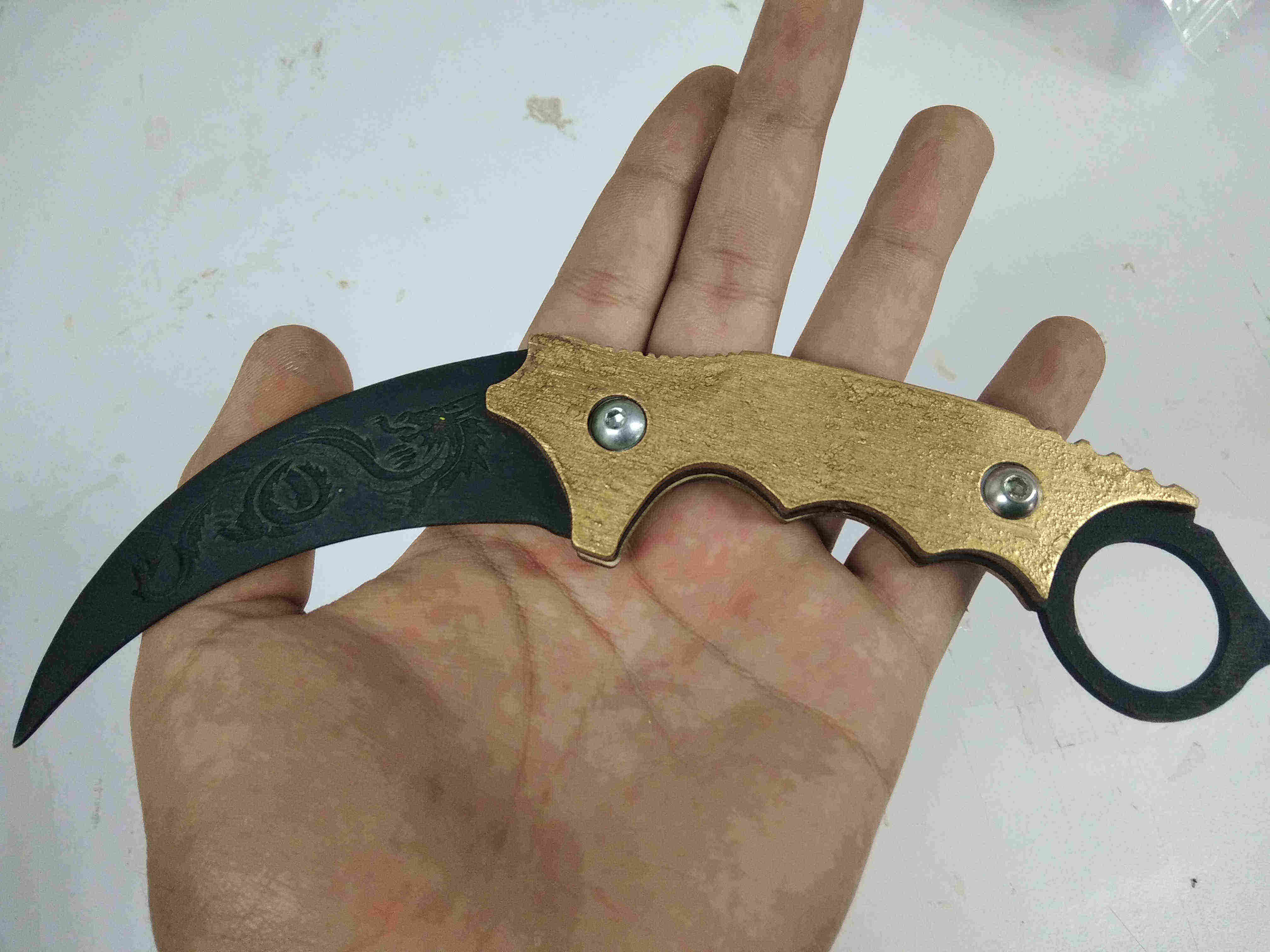
Blade
This part will be fun, It's Try to Produce something look Cool with the Laser cutter
open Fusion 360 and draw sketch for the blade
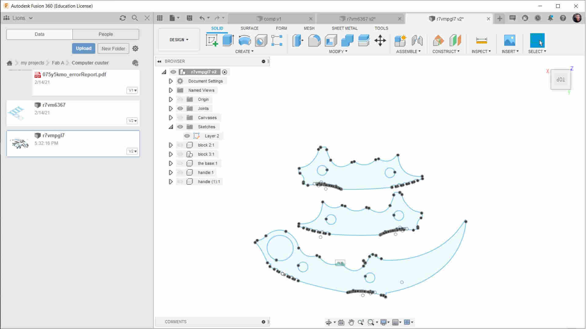
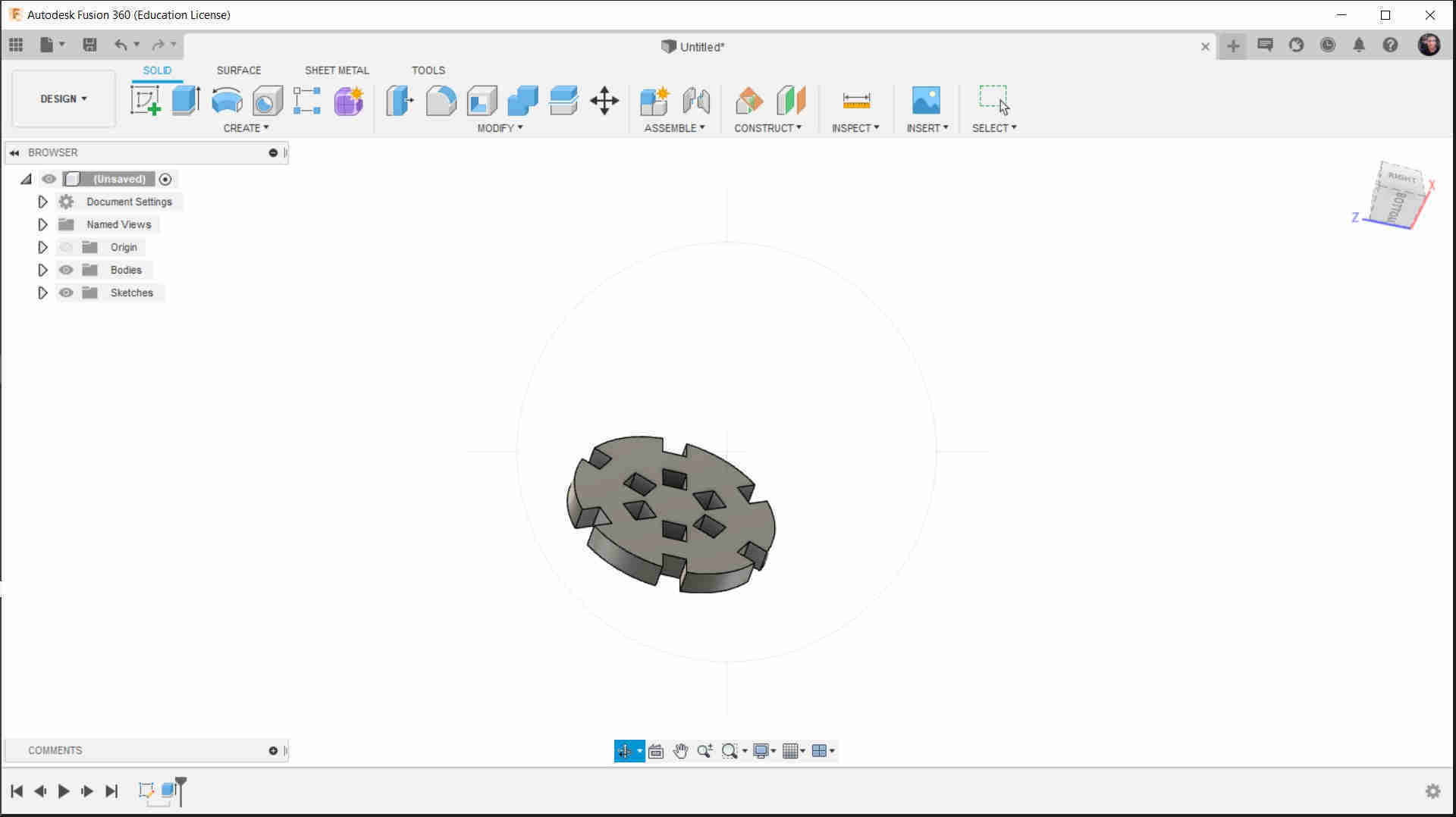
make Extrude and see how look like in the real
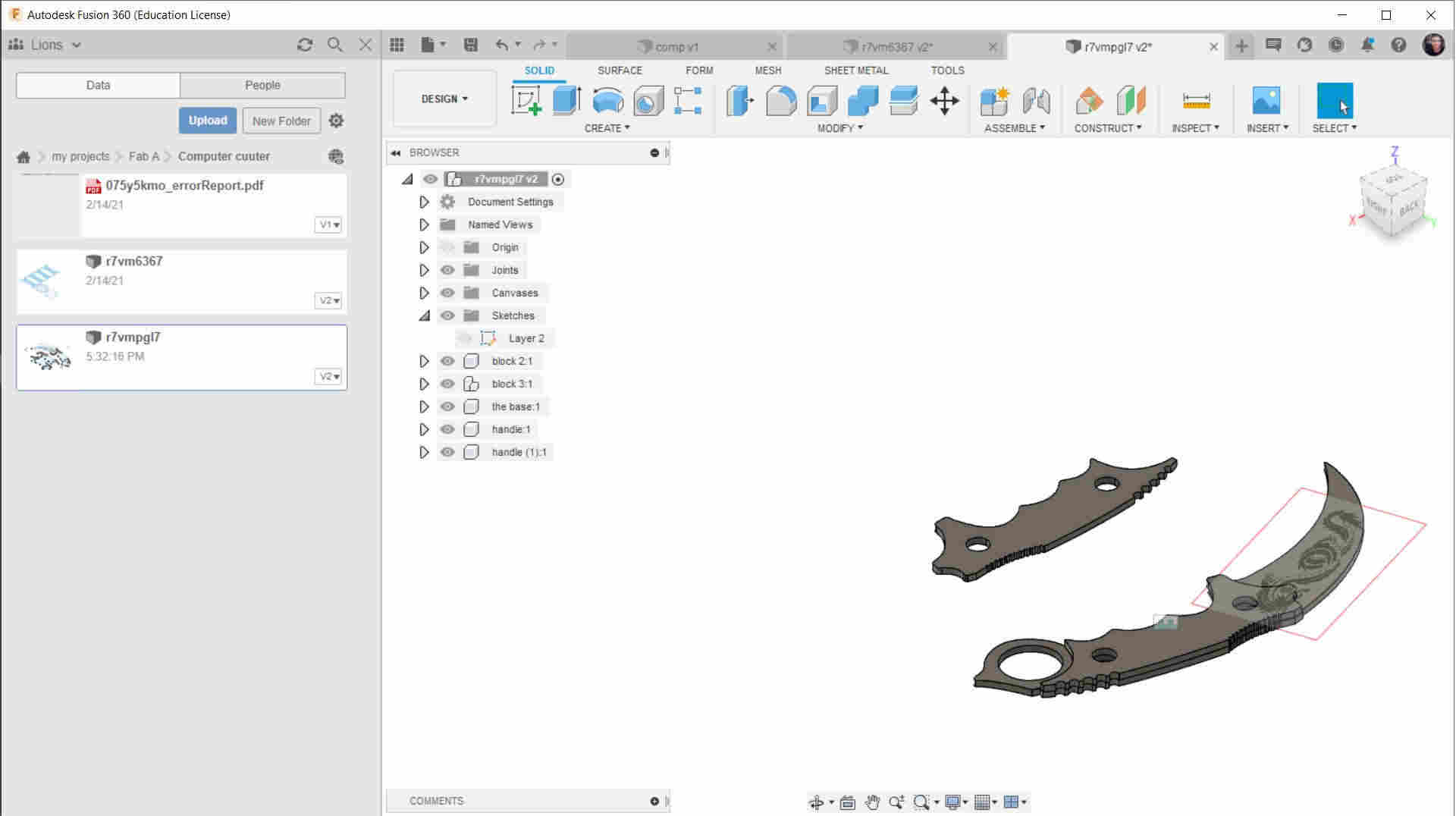
Try to imagine the colors

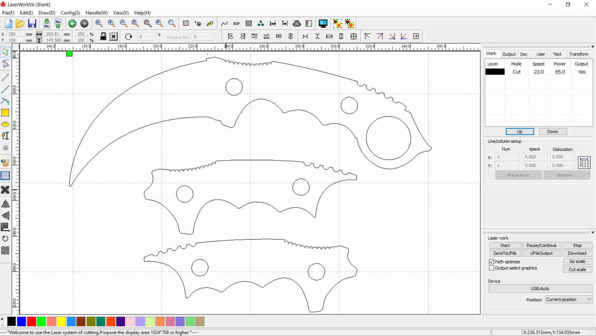
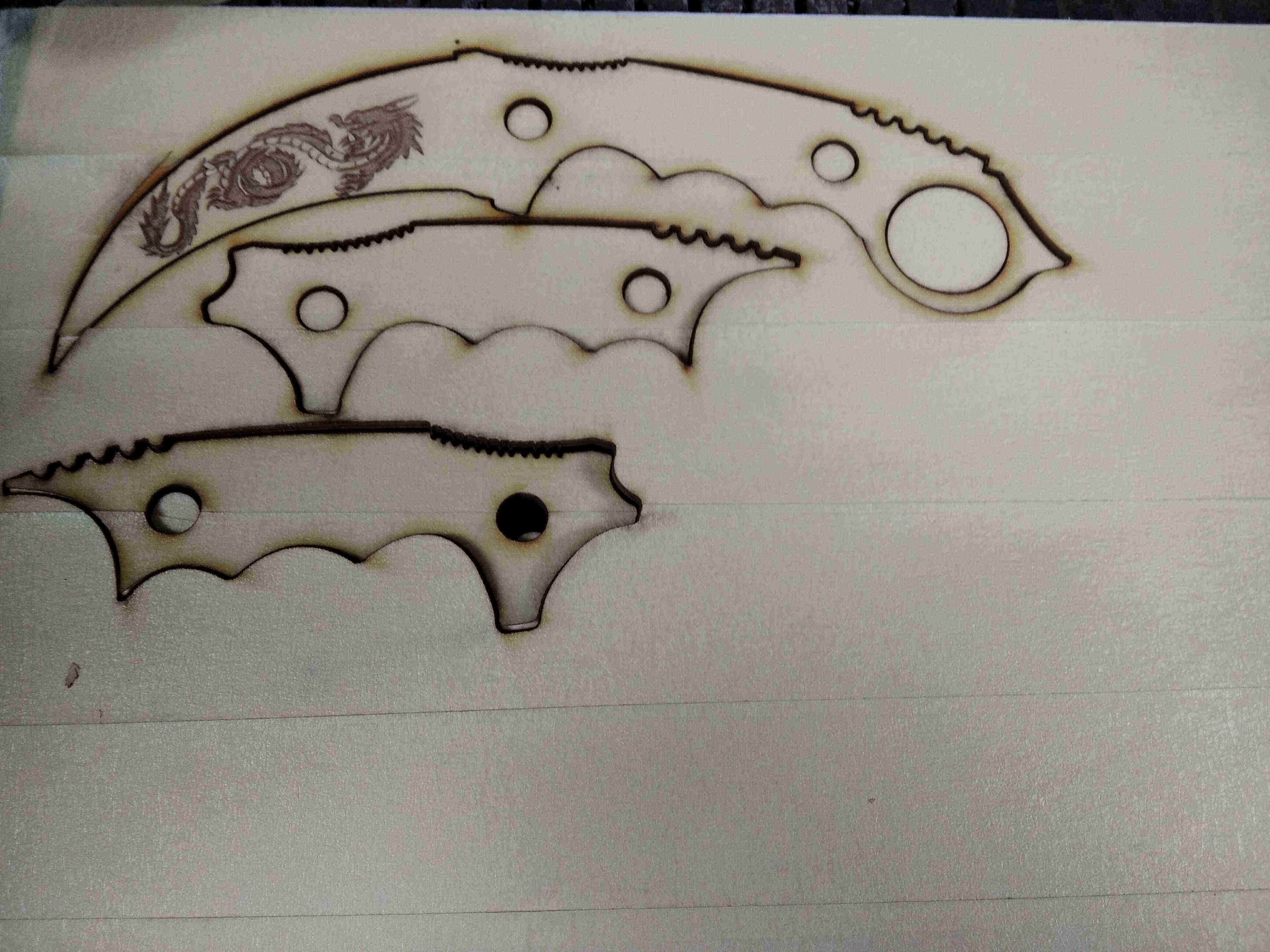
Put the DXF in Laser Works or Corel Draw
don't forget to put the dragon on the blade
and get out the blade from the plywood
Prepare the blade by sand it to make the blade smoother
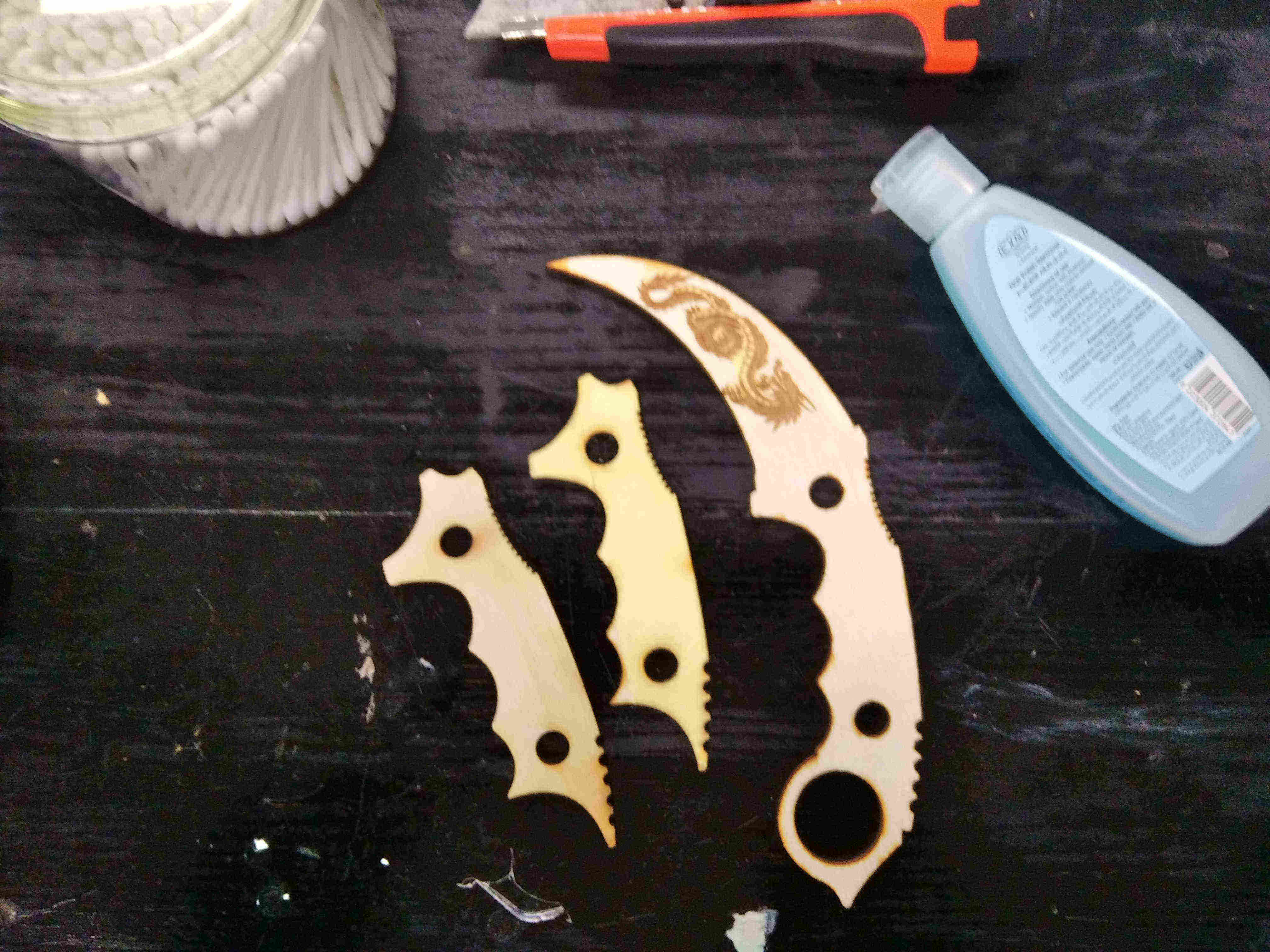
and after you paint it
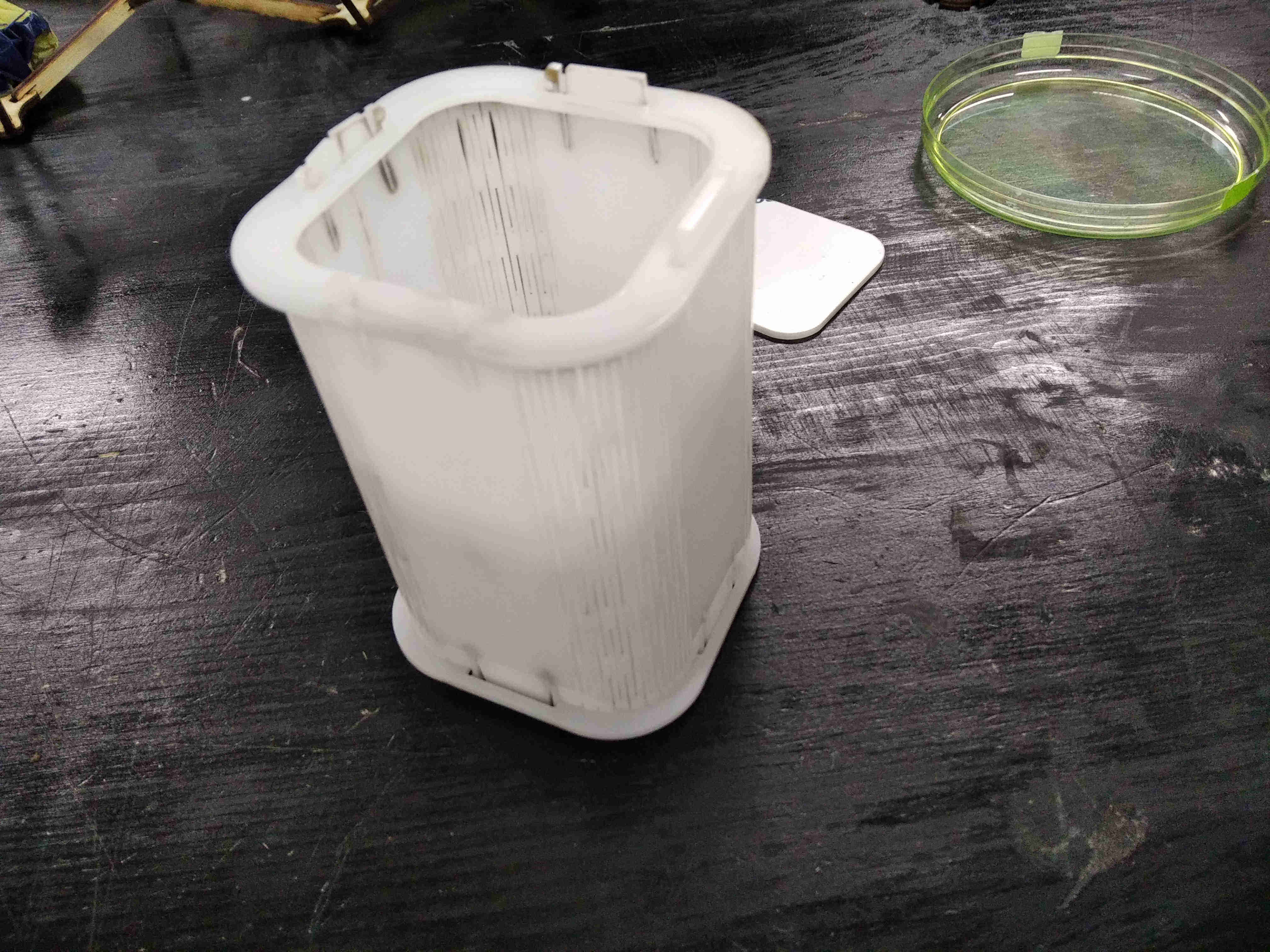
Acrilic
here I will make Box from acrylic to put the Pincels in it
Draw the Acrylic Skectch on Fusion 360
Put the Sketch on the Laser Works
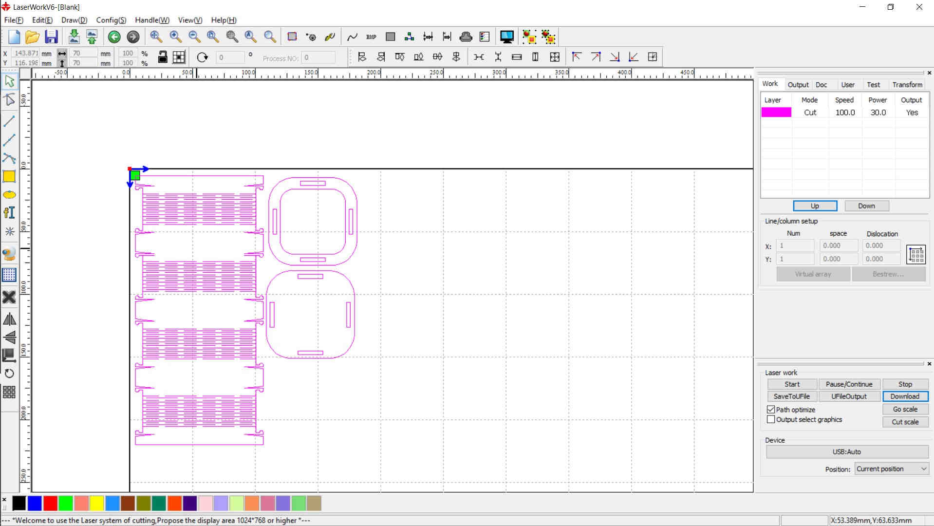
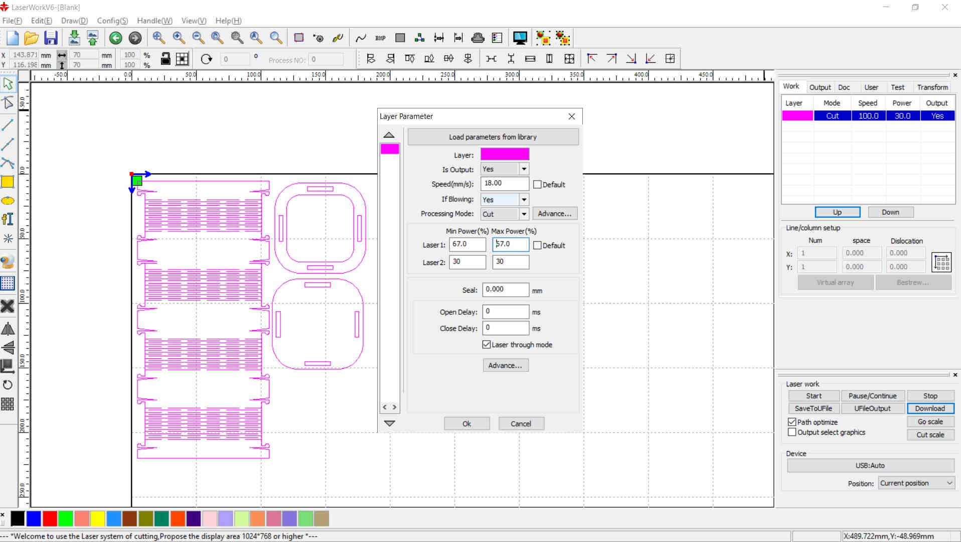
Modify the Speed and the Power of the Machine
Note
For Acrylic 3mm Cutting :
Speed (15mm/s)----Power (Min:65%---Max:65%)
For Acrylic 6mm Cutting :
Speed (8mm/s)----Power (Min:75%---Max:75%)
Cut the Acrylic sketch on the laser

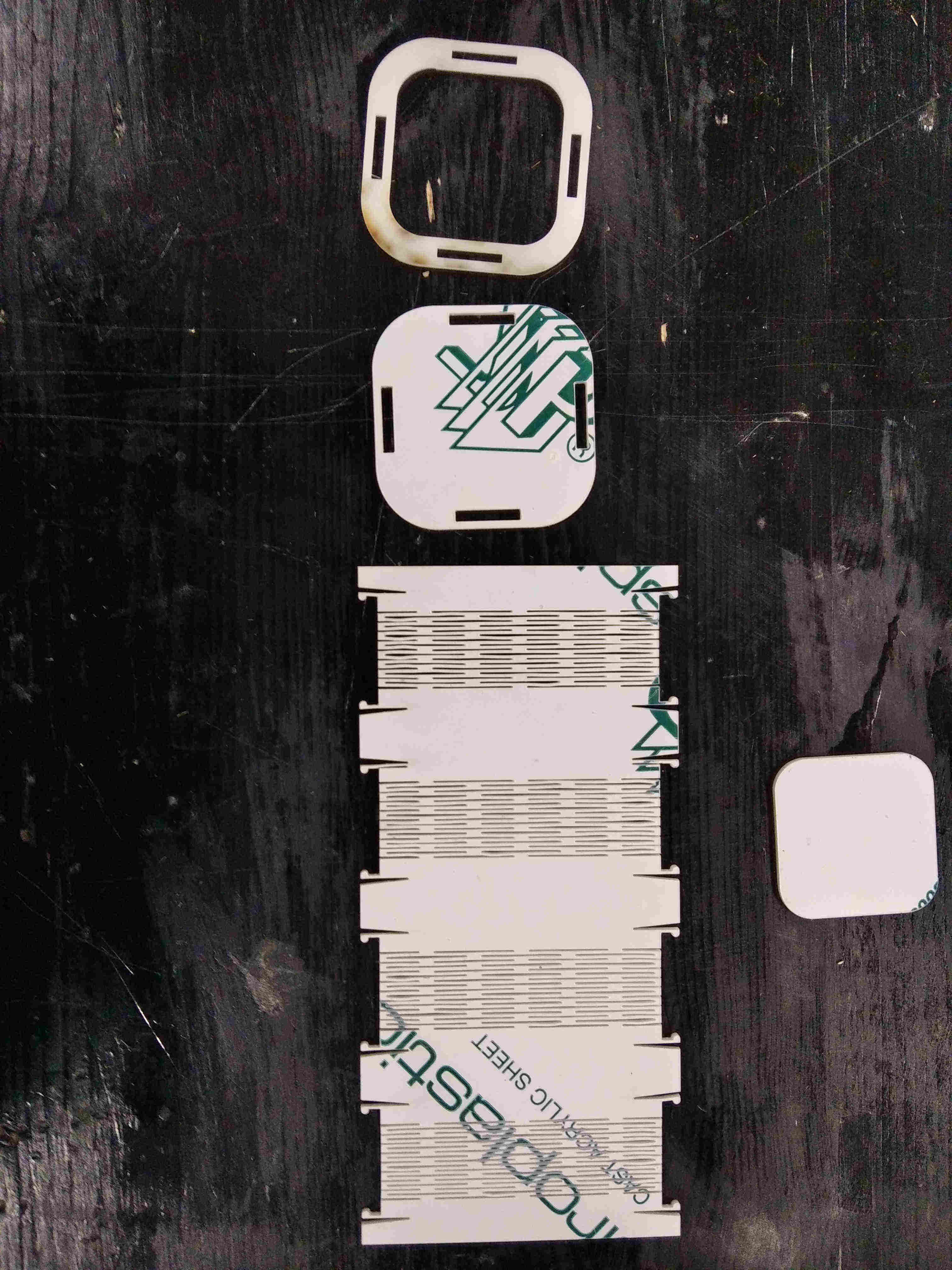
Assemble the Acrylic Box