Inspiration
I'm always atracting to Light Systems and light shows, and always want to make something like thoese light system into my home
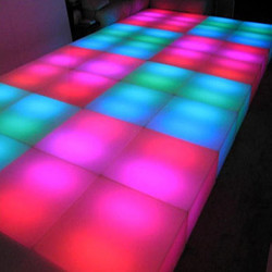
So I start Looking fro something to do realated to what I love, and after Searching I found the Nano-Leaf Light
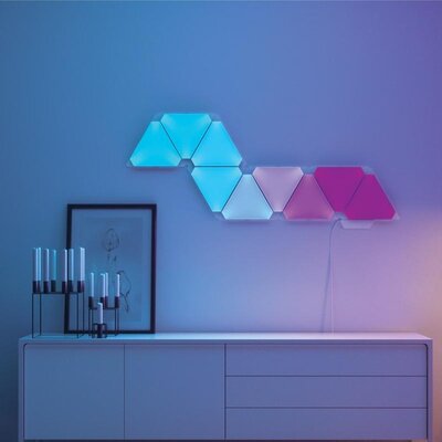
So Idecided to make the Nano-Leaf but in Simple and Cheap way
Proof-of-concept
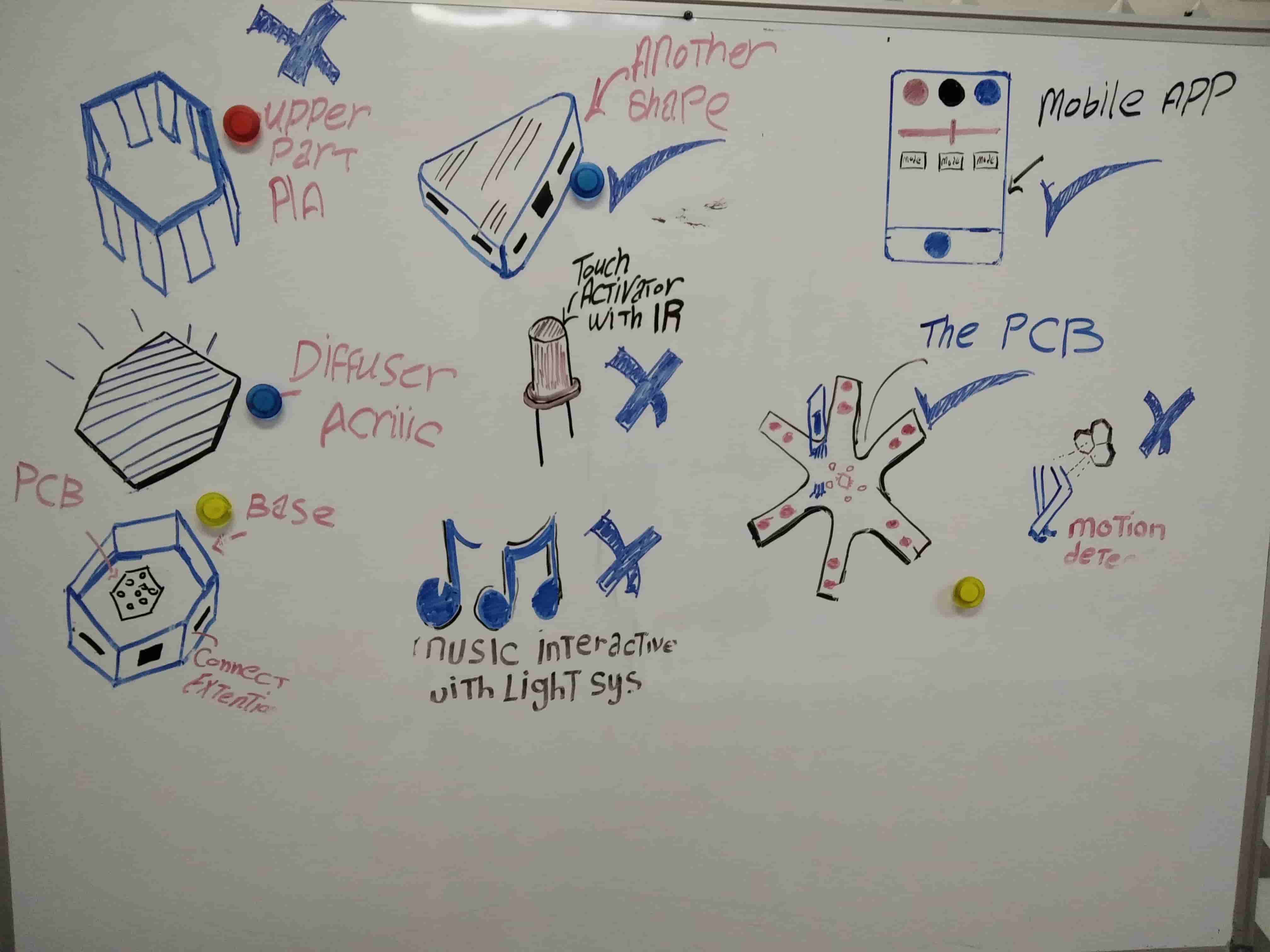
Before I start to make the Project I should orgnize my thoughts and Think how would I like to be my Project
So I start to make brain Storming and Put all the things I want on the board and later we will see which things we want to have and which things we will give away

so I start to make some Tests Begin in week 8 HERE
int Led2 = 10;
int Led1 = 9;
int Led3 = 2;
int Led4 = 8;
int Led5 = 3;
int Pushbutton = 7;
 void setup() {

  pinMode (Led1 , OUTPUT);
  pinMode (Led2 , OUTPUT);
  pinMode (Led3 , OUTPUT);
  pinMode (Led4 , OUTPUT);
  pinMode (Led5 , OUTPUT);
  pinMode (Pushbutton , INPUT);
  digitalWrite(Led1 , LOW);
  digitalWrite(Led2 , LOW);
  digitalWrite(Led3 , LOW);
  digitalWrite(Led4 , LOW);
  digitalWrite(Led5 , LOW);
    digitalWrite(Led5 , LOW);
    digitalWrite(Pushbutton , 1);

}

void loop() {
digitalWrite(Led1 , HIGH);
  delay (300);
  digitalWrite(Led2 , HIGH);
  delay (300);
  digitalWrite(Led3 , HIGH);
  delay (300);
  digitalWrite(Led4 , HIGH);
  delay (300);
  digitalWrite(Led5 , HIGH);
  delay (300);
  digitalWrite(Pushbutton , HIGH);
  delay (300);
  digitalWrite(Led1 , LOW);
  digitalWrite(Led2 , LOW);
  digitalWrite(Led3 , LOW);
  digitalWrite(Led4 , LOW);
  digitalWrite(Led5 , LOW);
  delay (300);
/*  ------------------- */
  digitalWrite(Led1 , HIGH);
  delay (250);
  digitalWrite(Led2 , HIGH);
  delay (250);
  digitalWrite(Led3 , HIGH);
  delay (250);
  digitalWrite(Led4 , HIGH);
  delay (250);
  digitalWrite(Led5 , HIGH);
  delay (250);
  digitalWrite(Pushbutton , HIGH);
  delay (250);
  digitalWrite(Led1 , LOW);
  digitalWrite(Led2 , LOW);
  digitalWrite(Led3 , LOW);
  digitalWrite(Led4 , LOW);
  digitalWrite(Led5 , LOW);
  delay (250);
  /*------------------ */
  digitalWrite(Led1 , HIGH);
  delay (200);
  digitalWrite(Led2 , HIGH);
  delay (200);
  digitalWrite(Led3 , HIGH);
  delay (200);
  digitalWrite(Led4 , HIGH);
  delay (200);
  digitalWrite(Led5 , HIGH);
  delay (200);
  digitalWrite(Pushbutton , HIGH);
  delay (200);
  digitalWrite(Led1 , LOW);
  digitalWrite(Led2 , LOW);
  digitalWrite(Led3 , LOW);
  digitalWrite(Led4 , LOW);
  digitalWrite(Led5 , LOW);
  delay (200);
  /*--------------- */
  digitalWrite(Led1 , HIGH);
  delay (150);
  digitalWrite(Led2 , HIGH);
  delay (150);
  digitalWrite(Led3 , HIGH);
  delay (150);
  digitalWrite(Led4 , HIGH);
  delay (150);
  digitalWrite(Led5 , HIGH);
  delay (150);
  digitalWrite(Pushbutton , HIGH);
  delay (150);
  digitalWrite(Led1 , LOW);
  digitalWrite(Led2 , LOW);
  digitalWrite(Led3 , LOW);
  digitalWrite(Led4 , LOW);
  digitalWrite(Led5 , LOW);
  delay (150);
  /*------------*/
  digitalWrite(Led1 , HIGH);
  delay (100);
  digitalWrite(Led2 , HIGH);
  delay (100);
  digitalWrite(Led3 , HIGH);
  delay (100);
  digitalWrite(Led4 , HIGH);
  delay (100);
  digitalWrite(Led5 , HIGH);
  delay (100);
  digitalWrite(Pushbutton , HIGH);
  delay (100);
  digitalWrite(Led1 , LOW);
  digitalWrite(Led2 , LOW);
  digitalWrite(Led3 , LOW);
  digitalWrite(Led4 , LOW);
  digitalWrite(Led5 , LOW);
  delay (100);
  /* ----------------- */
    digitalWrite(Led1 , HIGH);
  delay (50);
  digitalWrite(Led2 , HIGH);
  delay (50);
  digitalWrite(Led3 , HIGH);
  delay (50);
  digitalWrite(Led4 , HIGH);
  delay (50);
  digitalWrite(Led5 , HIGH);
  delay (50);
  digitalWrite(Pushbutton , HIGH);
  delay (50);
  digitalWrite(Led1 , LOW);
  digitalWrite(Led2 , LOW);
  digitalWrite(Led3 , LOW);
  digitalWrite(Led4 , LOW);
  digitalWrite(Led5 , LOW);
  delay (50);
}
The Logic of the code is too simple , All I made is to make the lamps turn on and turn off every beriod of time
I strte to make a simple version of code to test the pins and the function of the code
so from that I can Begin and make my own custom Circuit, All I want is to add blutooth and other Component and see the Result, So I will made a prototyping Circuit and fabricate it and see what it will End to
PCB Prototyping
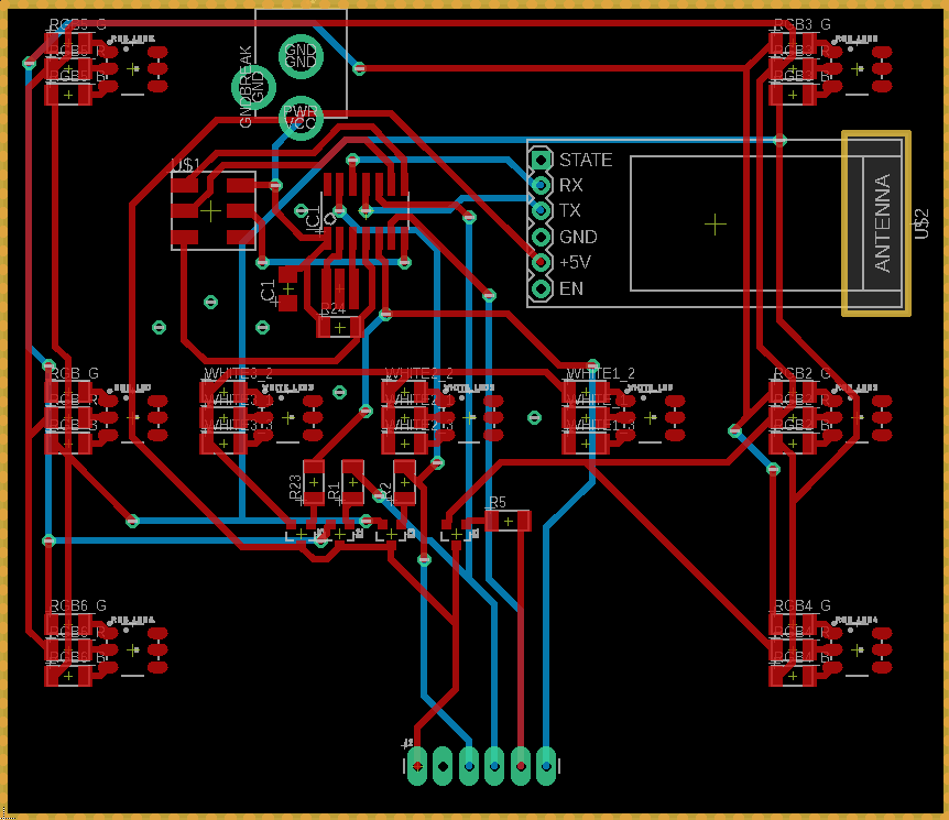
Making the Schematic
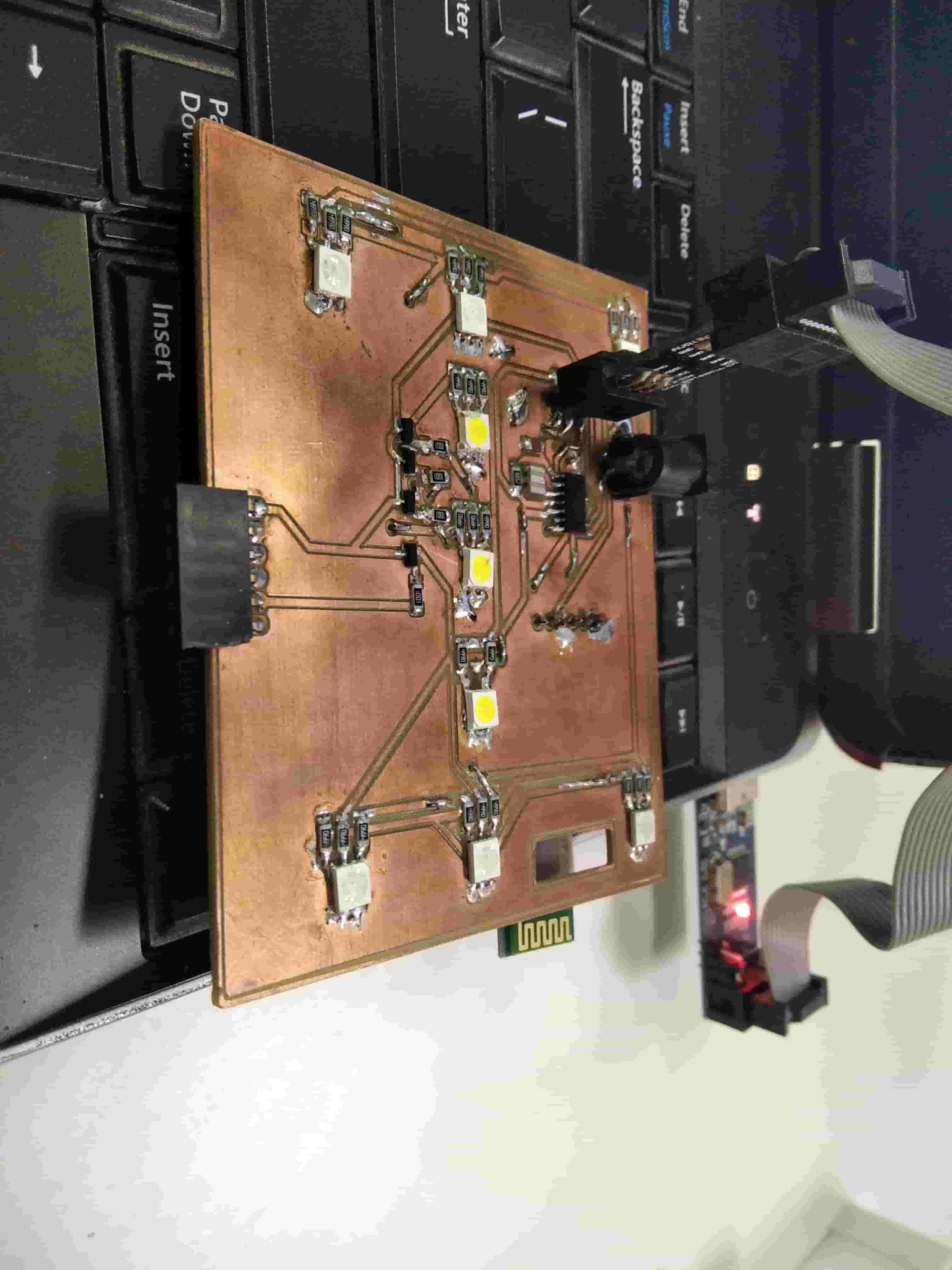
So now I'm making the Prototype Circuit
I used the Circuit that I made in the Week 14
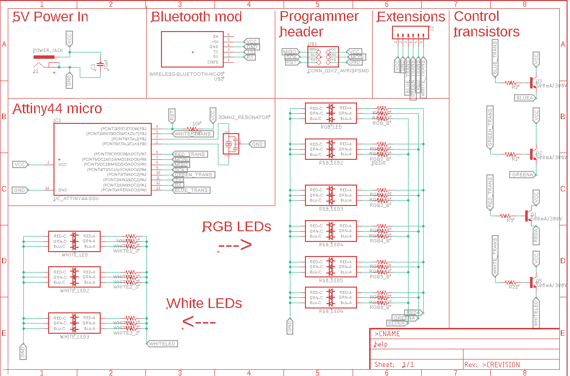
So as you can see I used Bluetooth module and Transistor NPN to manage the Power
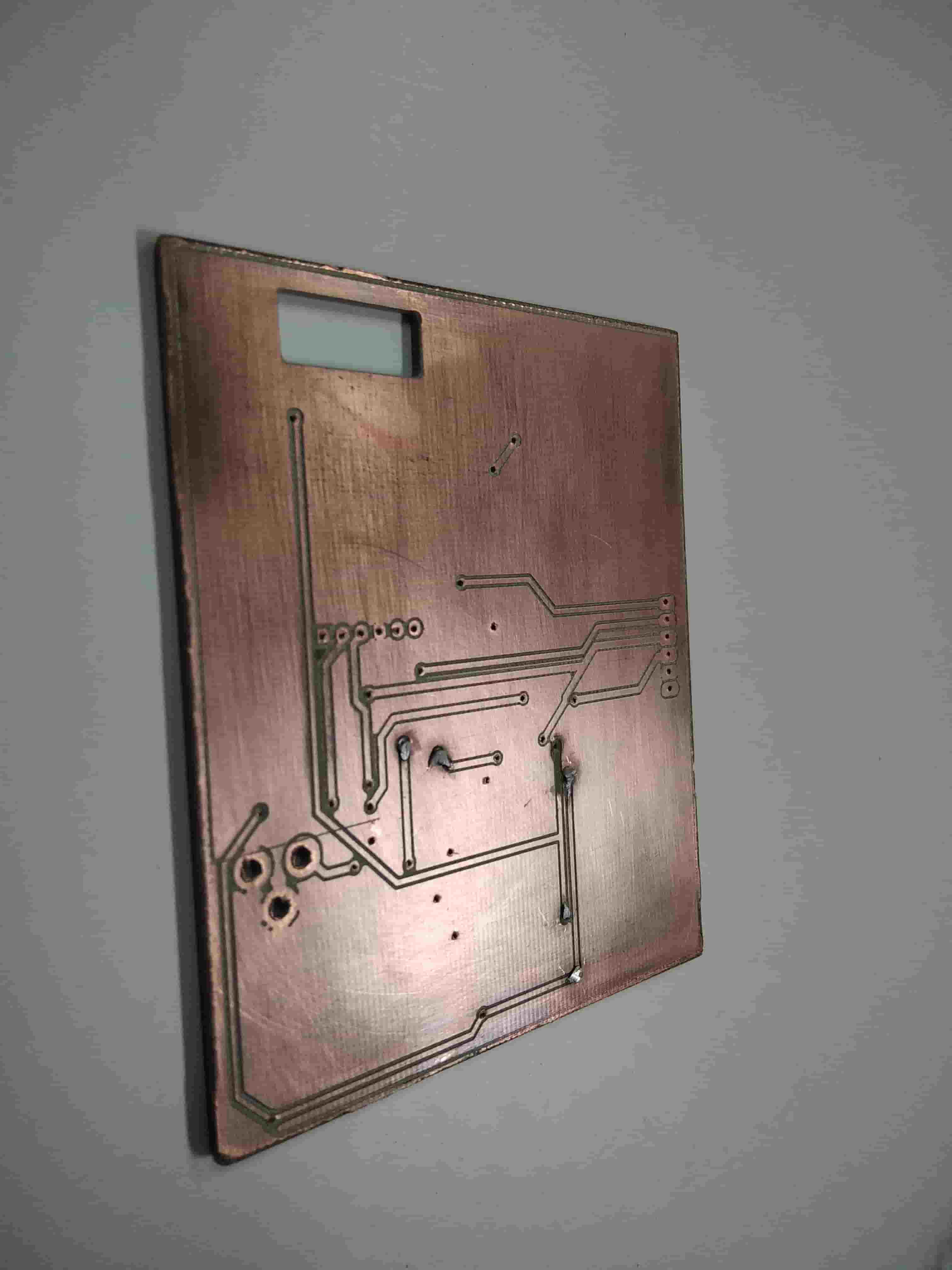
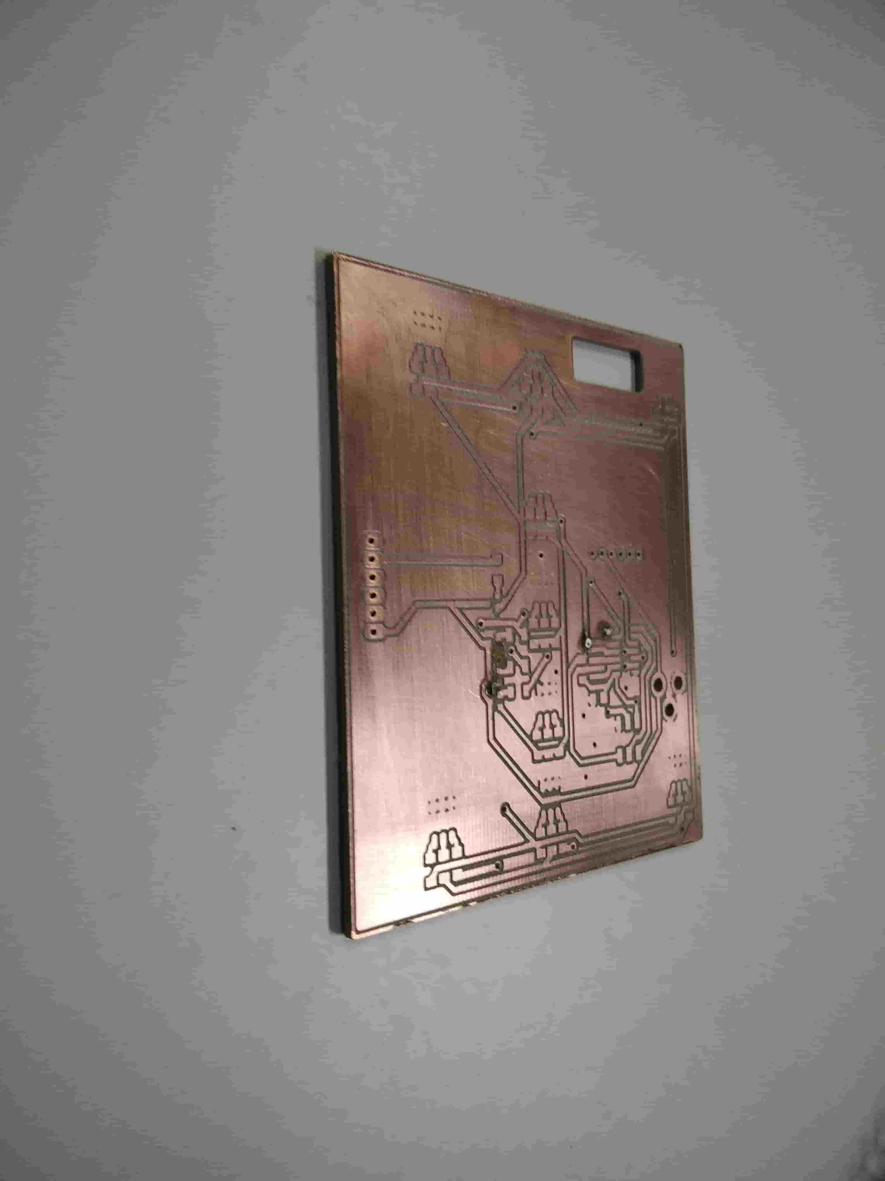
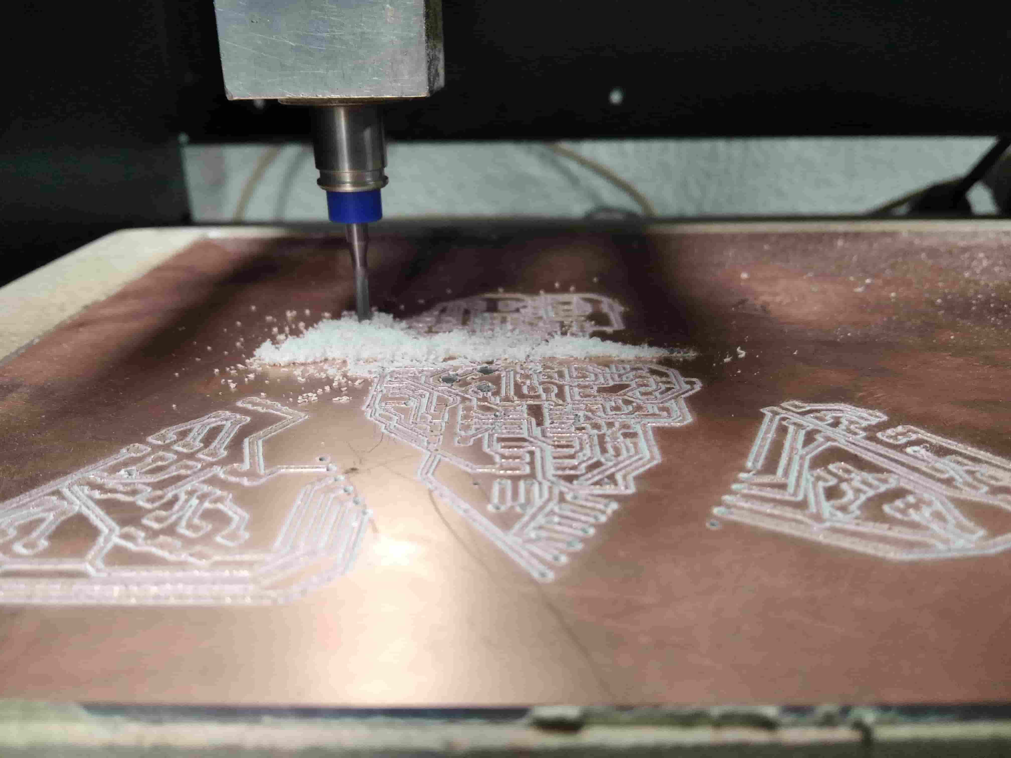
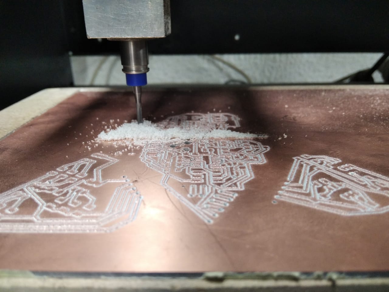
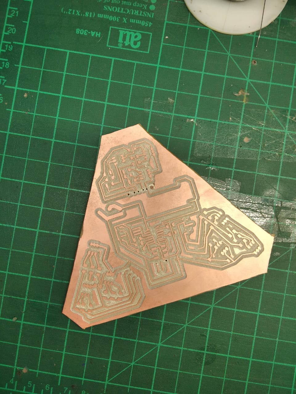
Fabricate & Soldering
So Start fabricate the PCB
and now for the Result
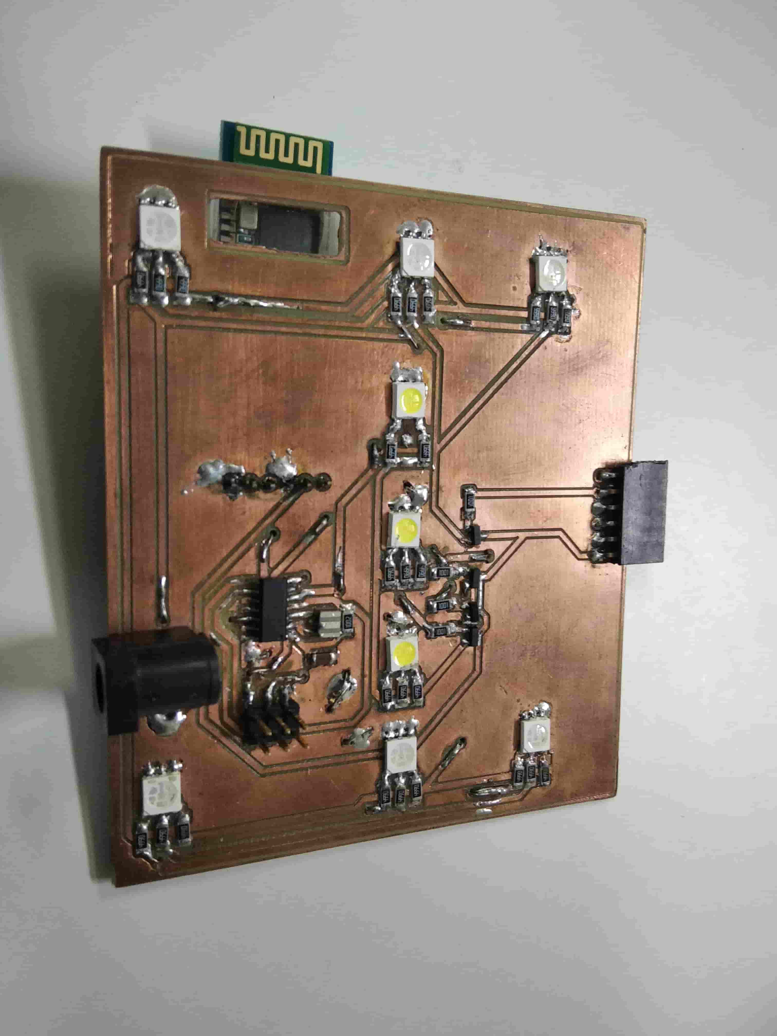
after that I wired the Components
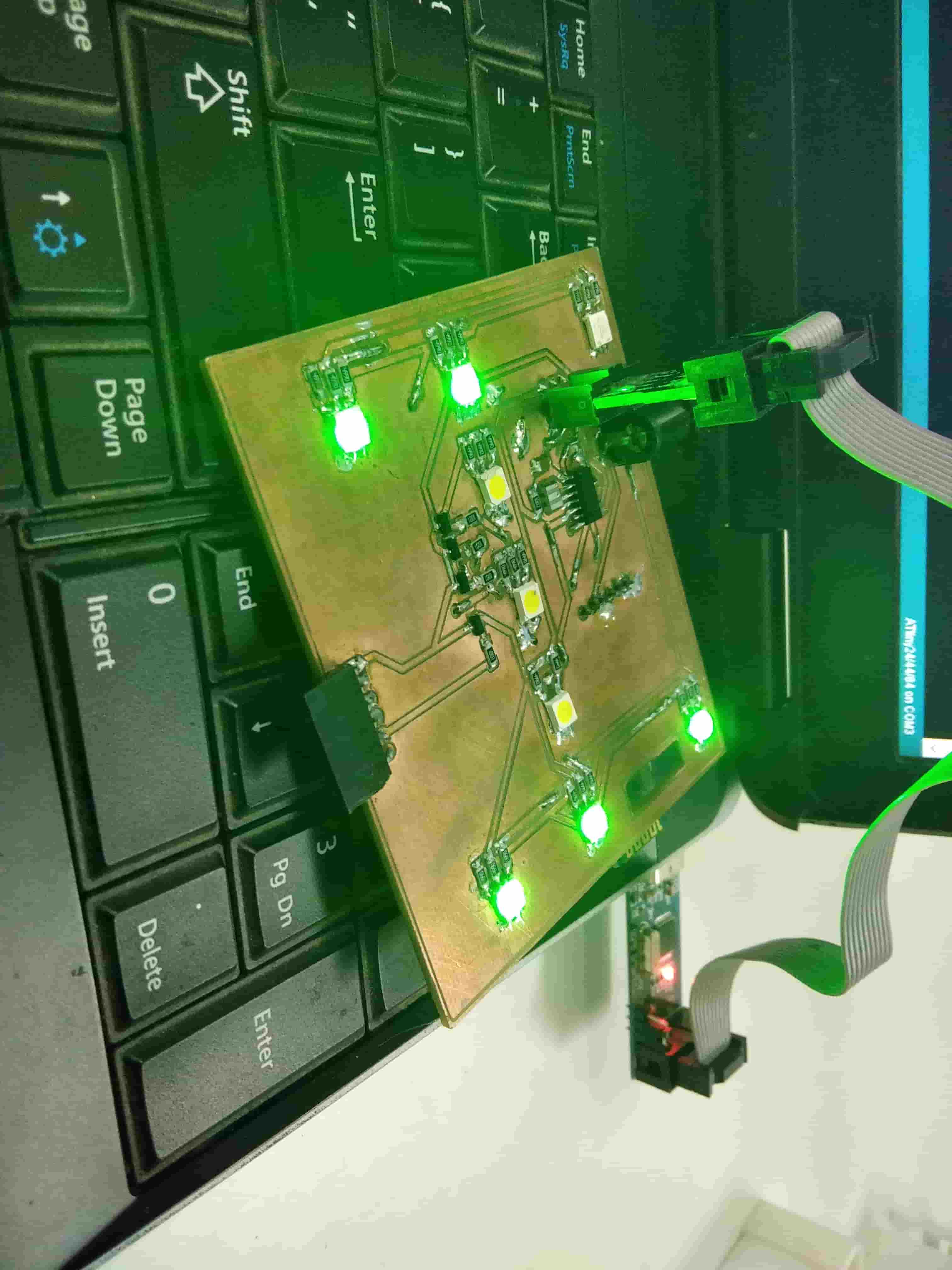
Coding
Uploading Plinking Code
                                       #define white 8
#define red 7
#define green 3
#define blue 9

void setup() {
  pinMode(white, OUTPUT);
  pinMode(red, OUTPUT);
  pinMode(green, OUTPUT);
}

void loop() {

  digitalWrite(red, HIGH);
  delay(500);
  digitalWrite(red, LOW);
  digitalWrite(green, HIGH);
  delay(500);
  digitalWrite(green, LOW);
  delay(500);
  digitalWrite(white, HIGH);
  delay(500);
  digitalWrite(white, LOW);
  delay(1000);

}
And then we added the Bluetooth
#include
SoftwareSerial mySerial(2, 1); // RX, TX

#define white 8
#define red 7
#define green 3
#define blue 0

unsigned int incomingData;
unsigned int incomingData1;
unsigned int incomingDataRAW;
int whiteColorIntensity = 0;
int previousIncomingData;

void setup() {

  mySerial.begin(9600);

  pinMode(white, OUTPUT);
  pinMode(red, OUTPUT);
  pinMode(green, OUTPUT);
  pinMode(blue, OUTPUT);
}

void loop() {
  if (mySerial.available() >= 2 ) // receive number from bluetooth
  {

    incomingData = mySerial.read();
    incomingData1 = mySerial.read();
    incomingDataRAW = (incomingData1 * 256) + incomingData;

    if (incomingDataRAW > 4) {
      whiteColorIntensity = incomingDataRAW;
      incomingDataRAW = previousIncomingData;
    }
  }

  if (incomingDataRAW == 1) {
    previousIncomingData = incomingDataRAW;
    digitalWrite(red, HIGH);
    delay(500);
    digitalWrite(red, LOW);
    digitalWrite(green, HIGH);
    delay(500);
    digitalWrite(green, LOW);
    digitalWrite(blue, HIGH);
    delay(500);
    digitalWrite(blue, LOW);
    digitalWrite(white, HIGH);
    delay(500);
    digitalWrite(white, LOW);
    delay(1000);
  }
  else if (incomingDataRAW == 2) {
    previousIncomingData = incomingDataRAW;
    digitalWrite(red, HIGH);
    delay(100);
    digitalWrite(red, LOW);
    digitalWrite(green, HIGH);
    delay(100);
    digitalWrite(green, LOW);
    digitalWrite(blue, HIGH);
    delay(100);
    digitalWrite(blue, LOW);
    digitalWrite(white, HIGH);
    delay(100);
    digitalWrite(white, LOW);
    delay(10);
  }
  else if (incomingDataRAW == 3) {
    previousIncomingData = incomingDataRAW;
    analogWrite(white, whiteColorIntensity);
  }
  else if (incomingDataRAW == 0) {
    digitalWrite(red, LOW);
    digitalWrite(green, LOW);
    digitalWrite(blue, LOW);
    digitalWrite(white, LOW);
  }
}
And Let's see the Video
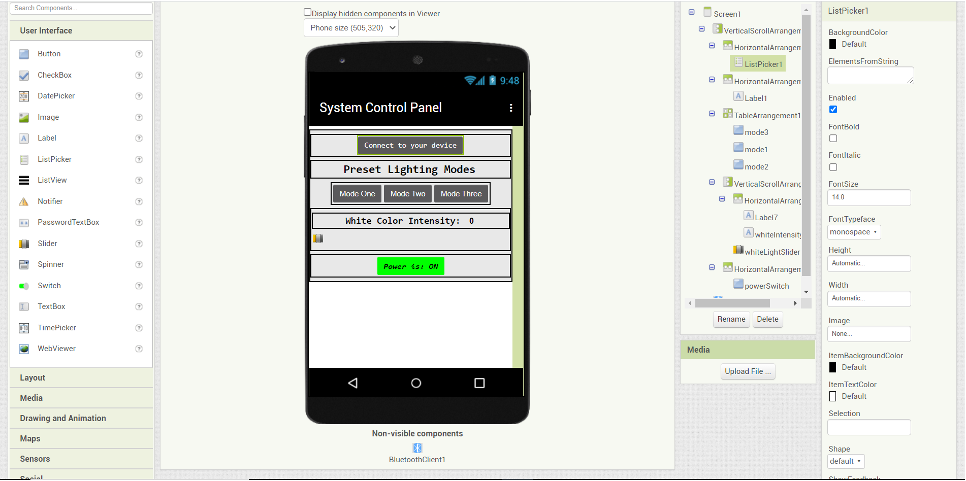
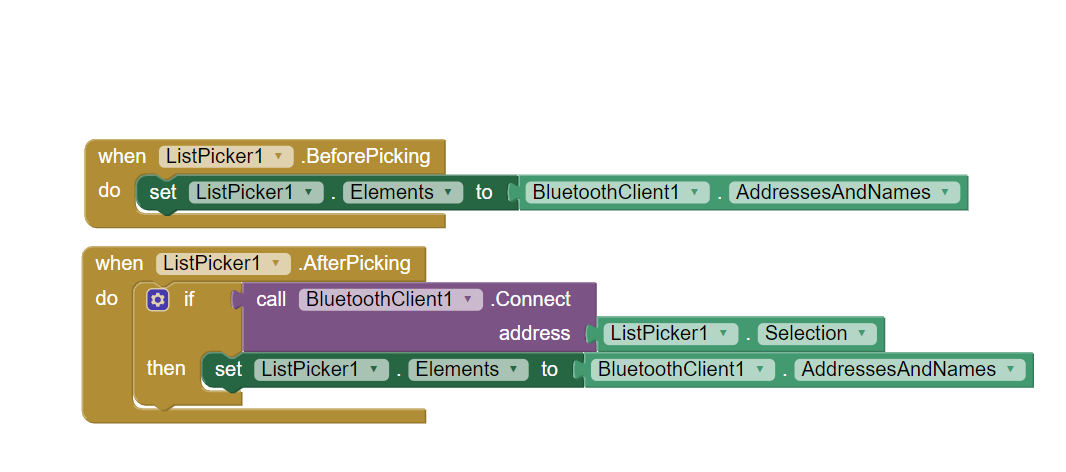
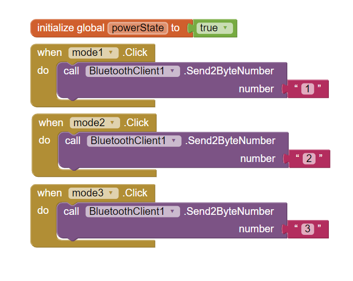
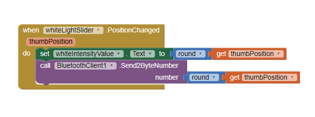
Mobile Application building
I designed my Code on App Inventor
for more information you can Visit Week 8
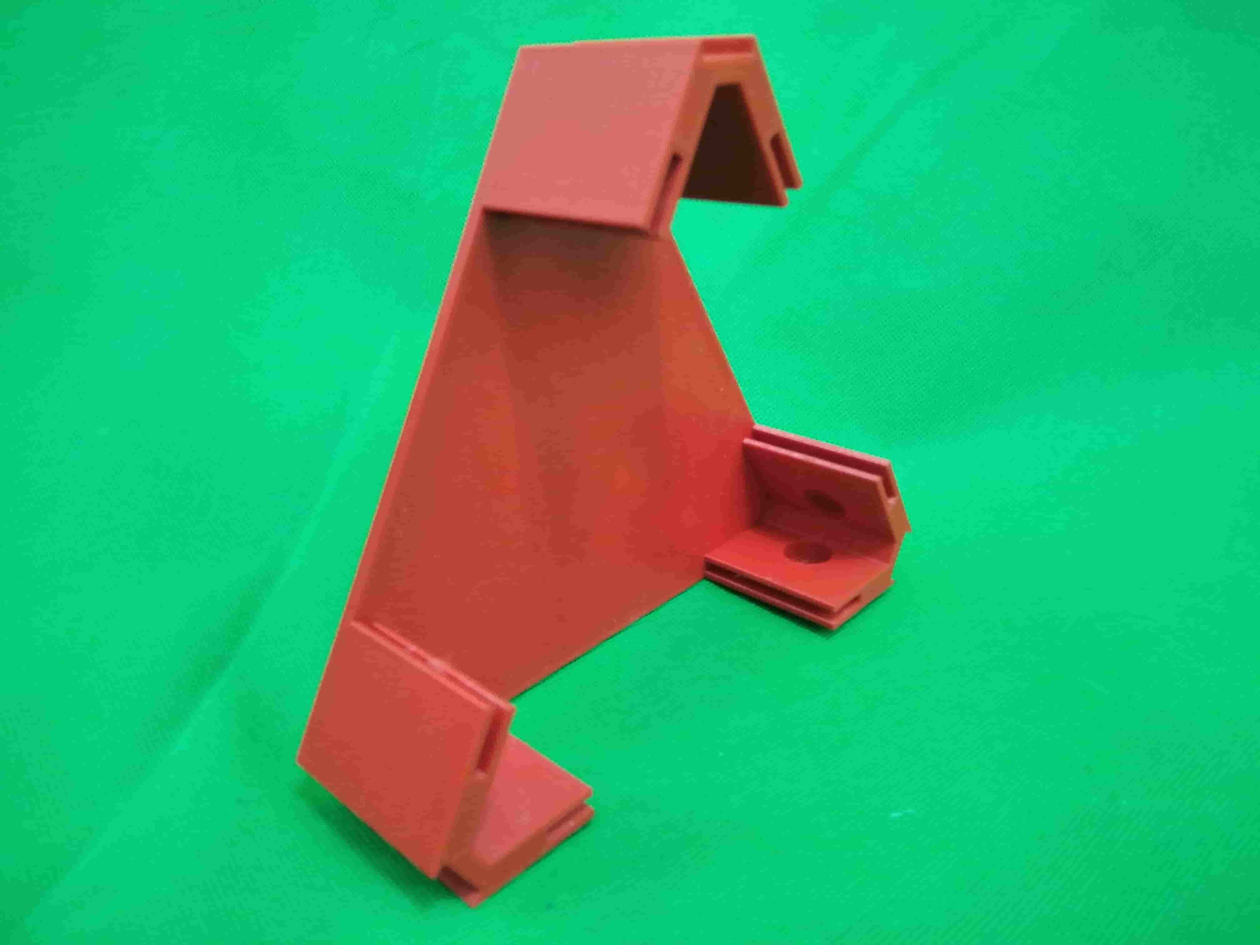
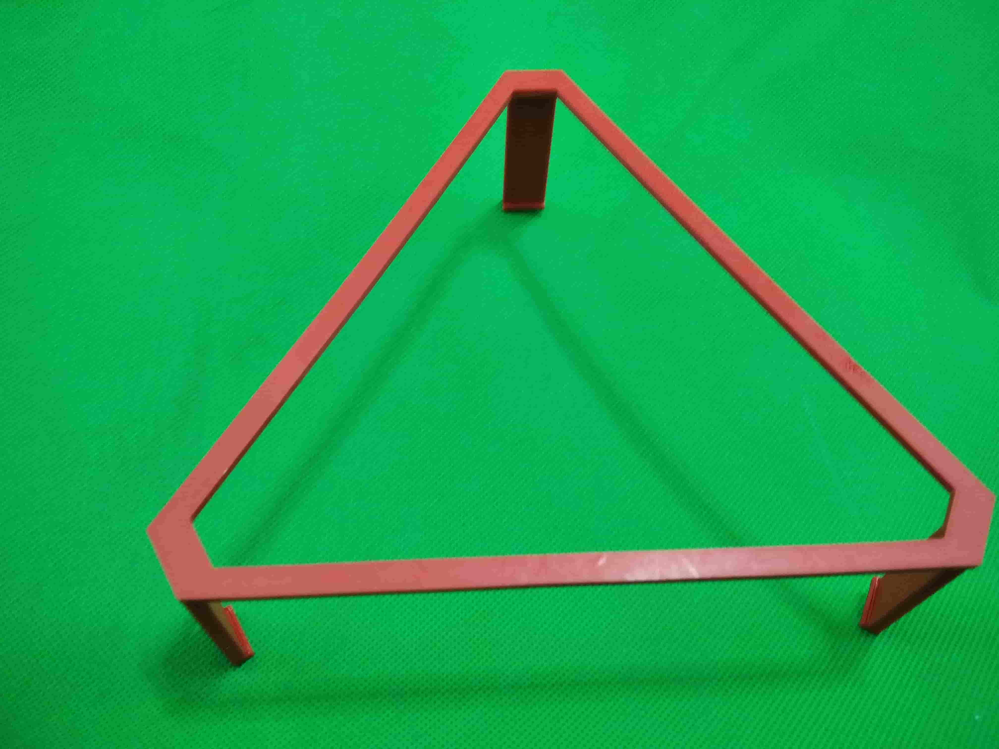
Enclosure Prototyping
In this part I made Alot of Enclosures Prototypees
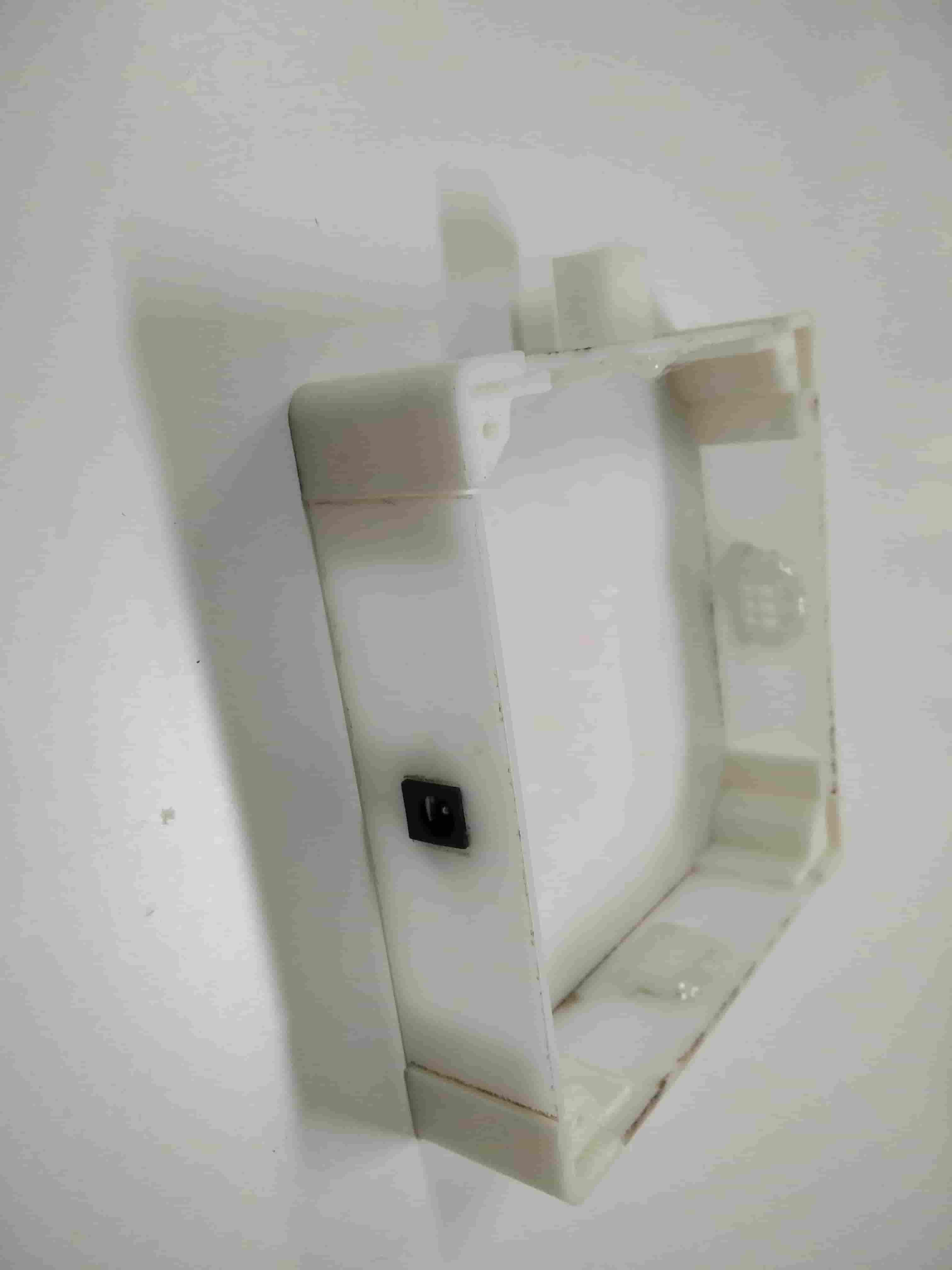
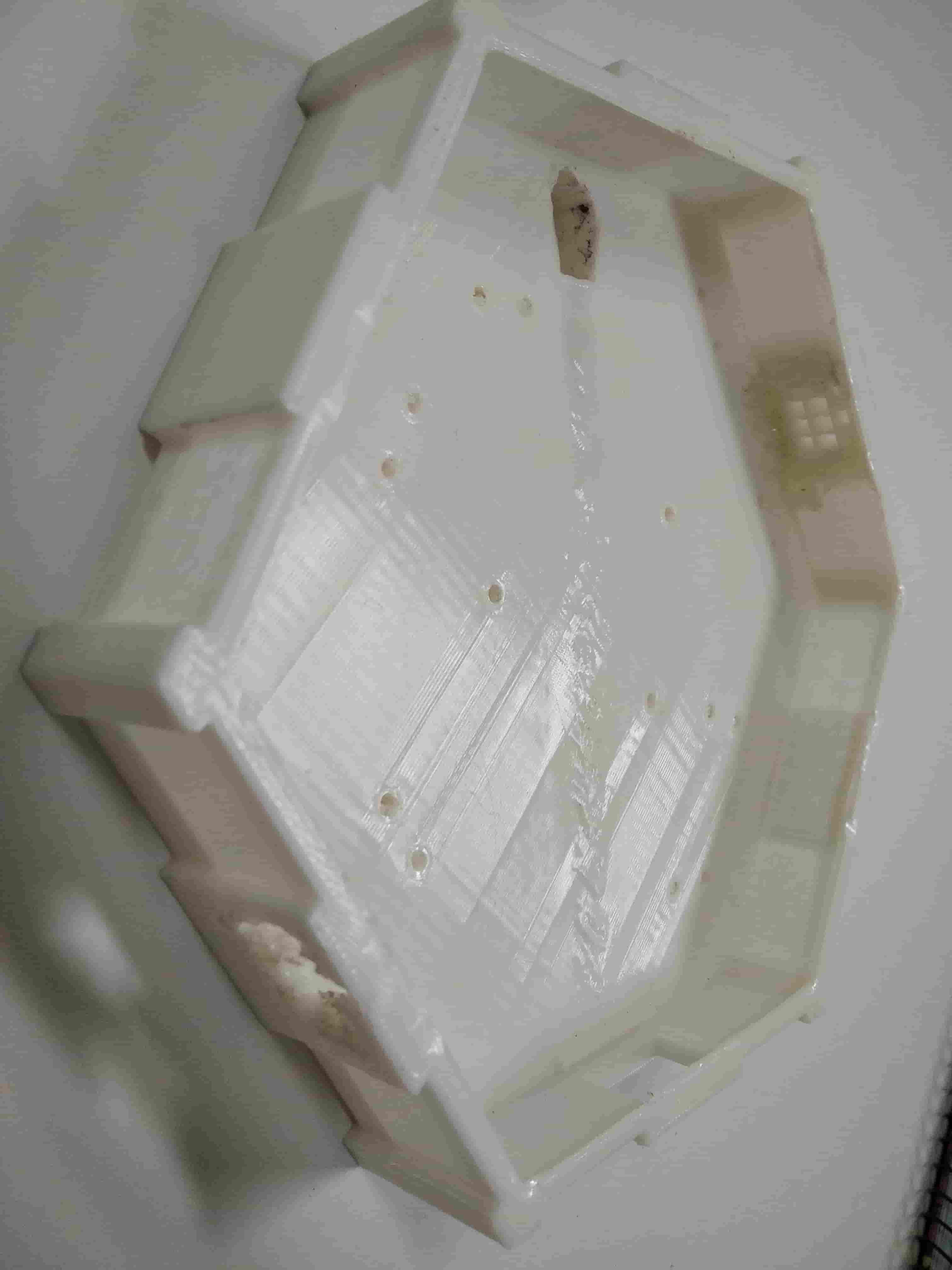
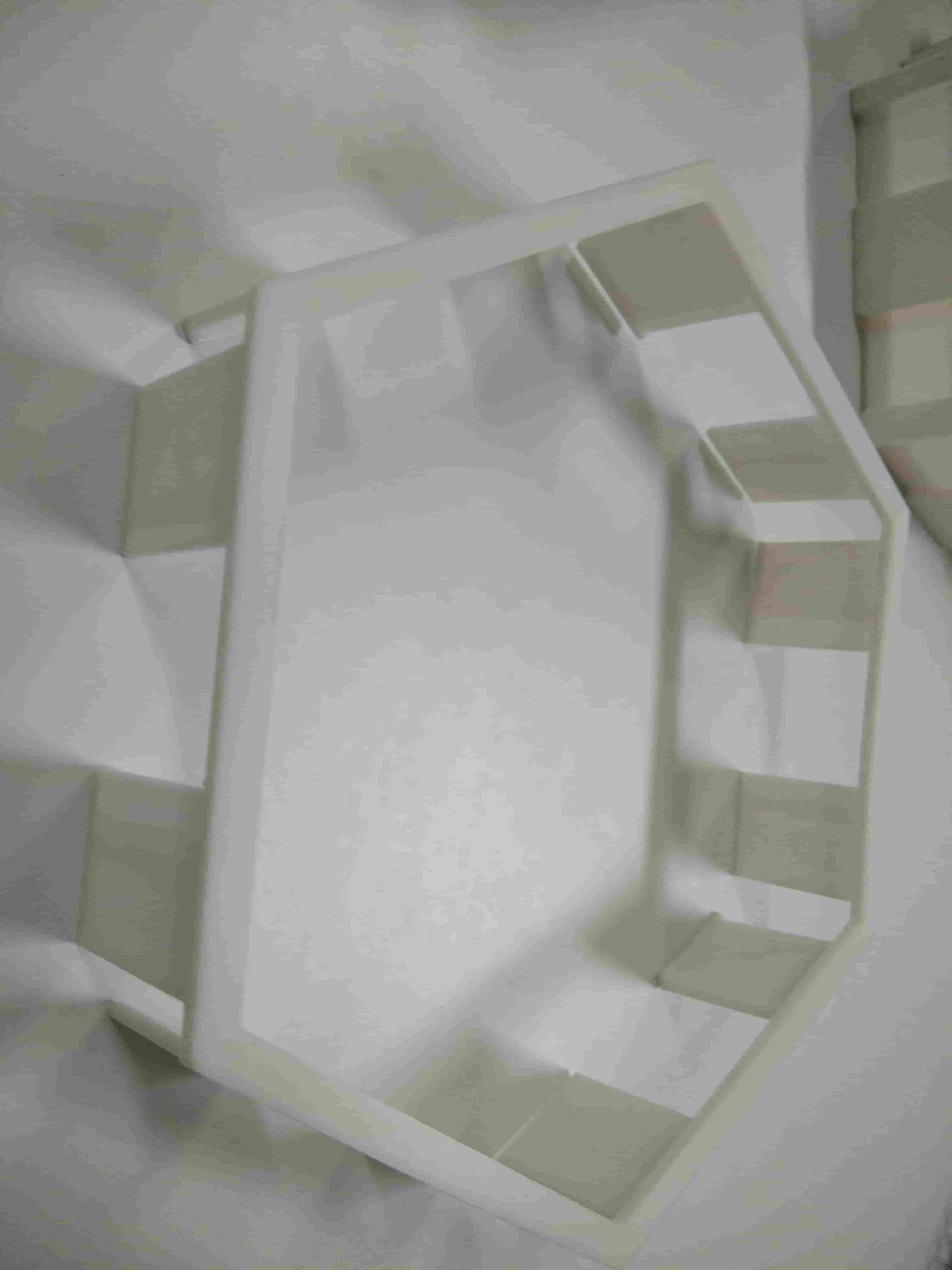
and Decided to Conteniue the Prototyping with the Hexagonal Shape
I wouldn't go in detail how I made It You will see How I made the Final one Later on
I put the Prototyping Board into our Prototyping Enclosure To Se the Result
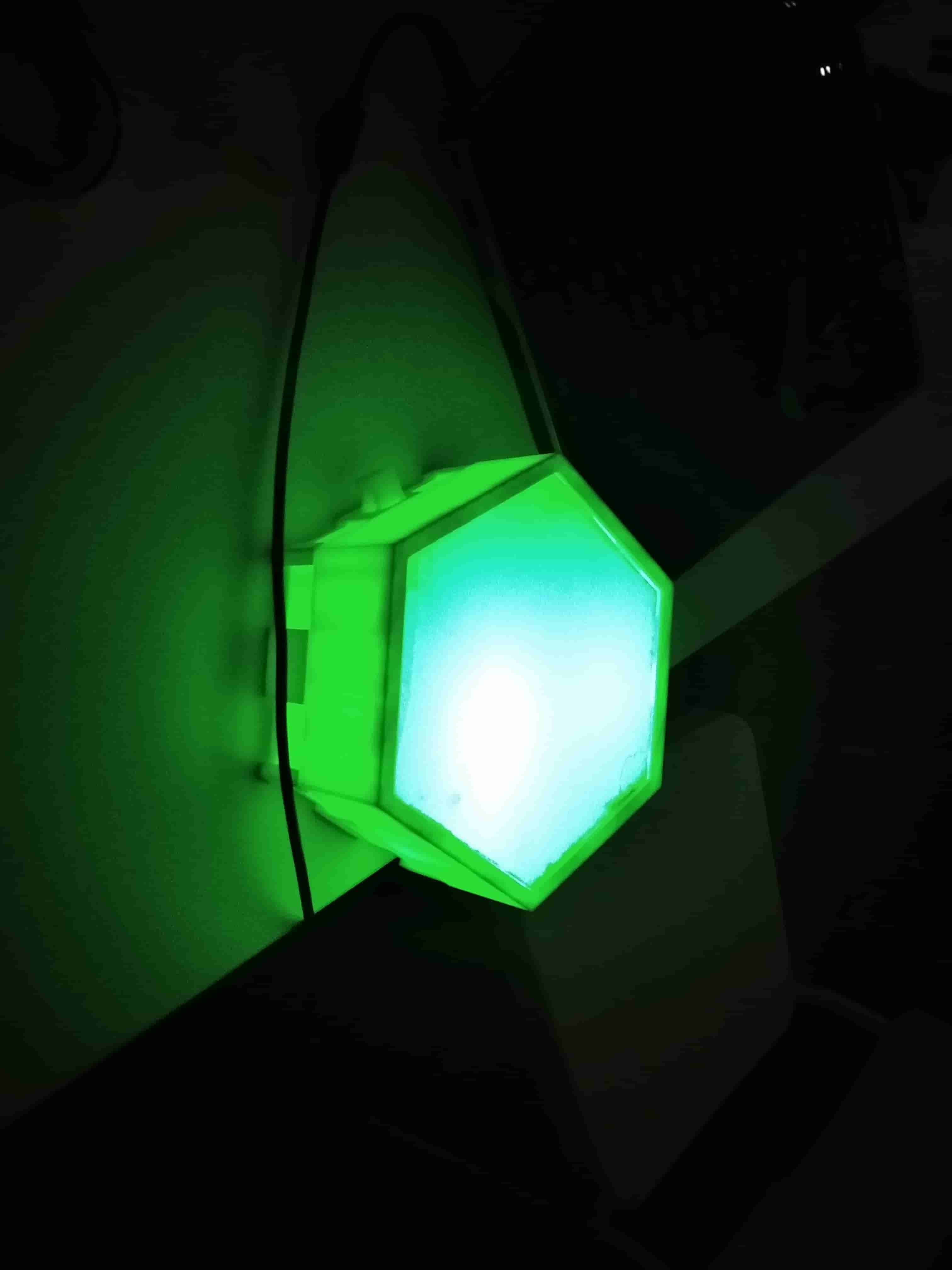
And Let's see the Video
So Finally It Works Every thing Is Ok now, We Shouldn't have Trouble in the next Stage Right ?!
Enclosure Production
after the Phase of Prototyping and Testing, I'm now have a clear Vision of what I should do
Lest's Update our Board shall we
So we will make our Enclosure on the Shape of Rectangle not Hexagonal
our Design will be mainly Saperated intoTwo part the Base and the Top
the Base will holding the PCB and the Components and the Top Will Holding the Acrylic
So I will Begin with Designing
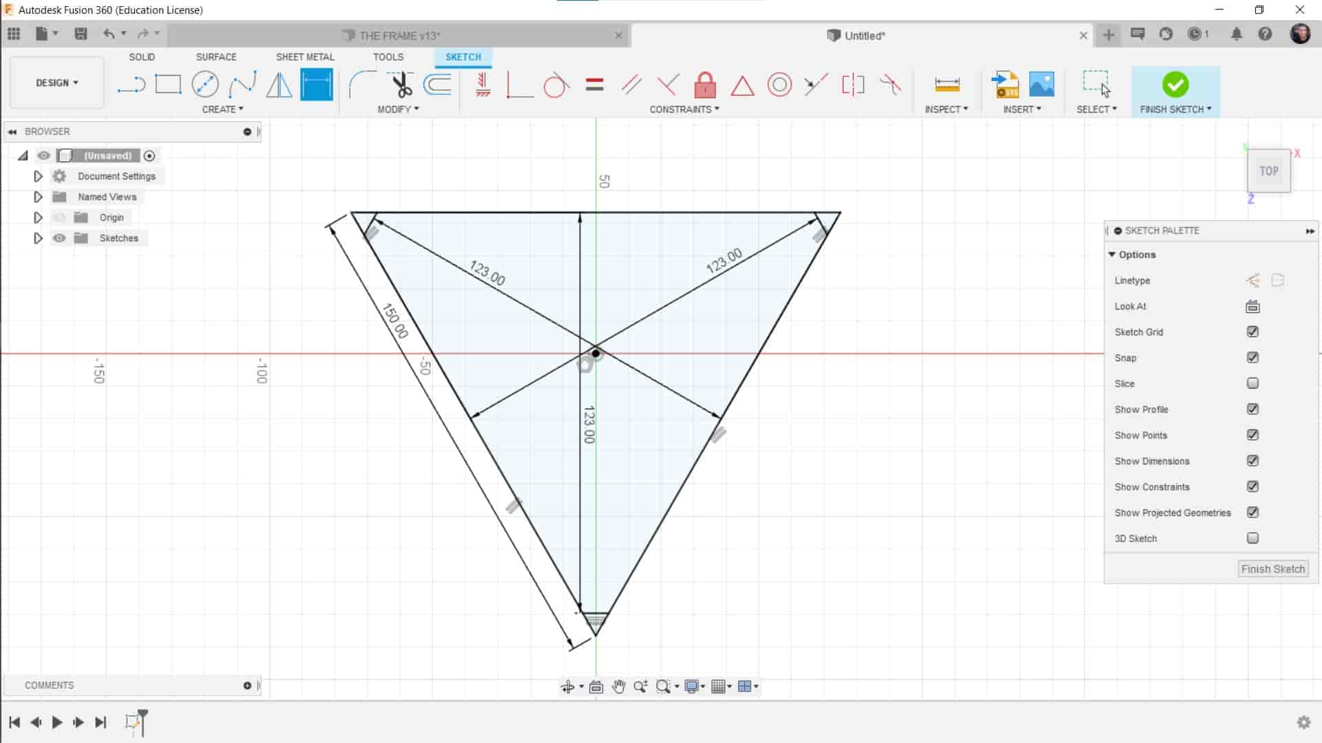
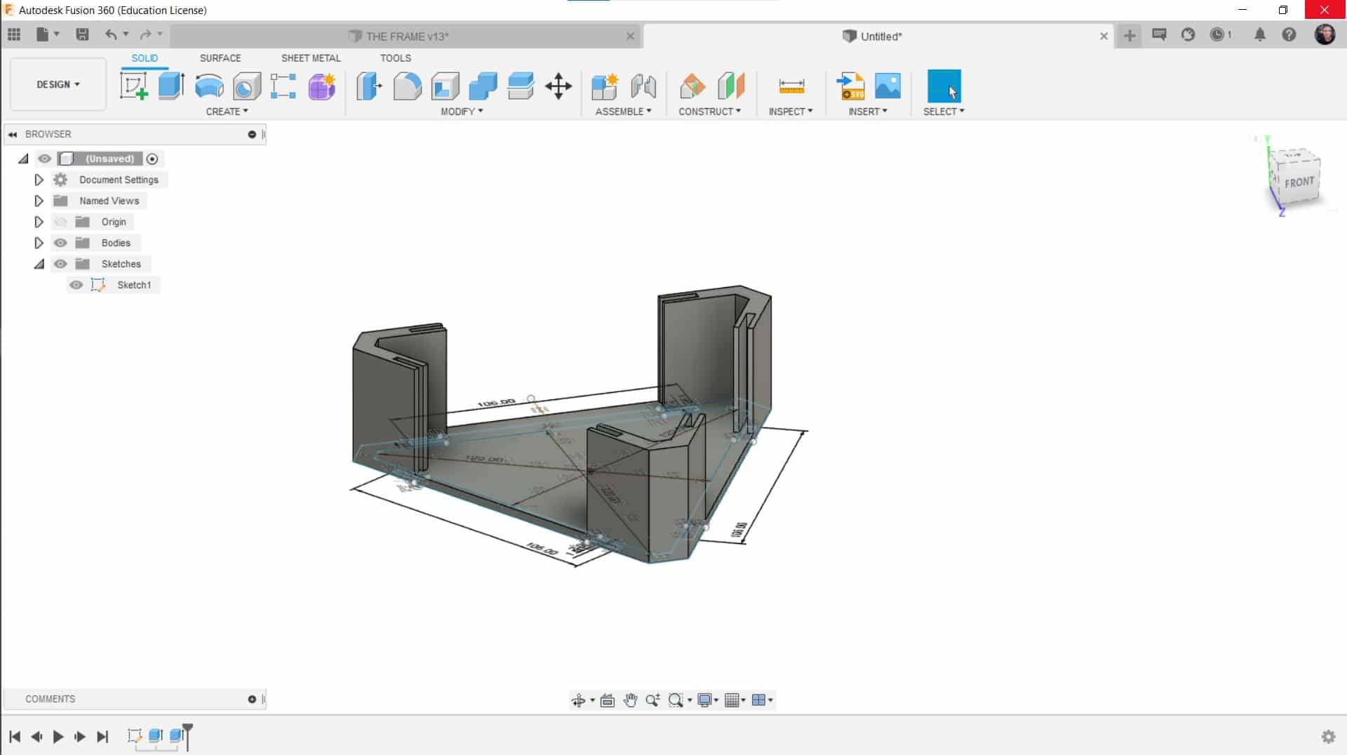
Designinig
Open Fusion 360 and make Sketch and Begin to Draw ( don't Worry I will leave the Files Down Below)
And The Extruding the Base Bart of the Shape
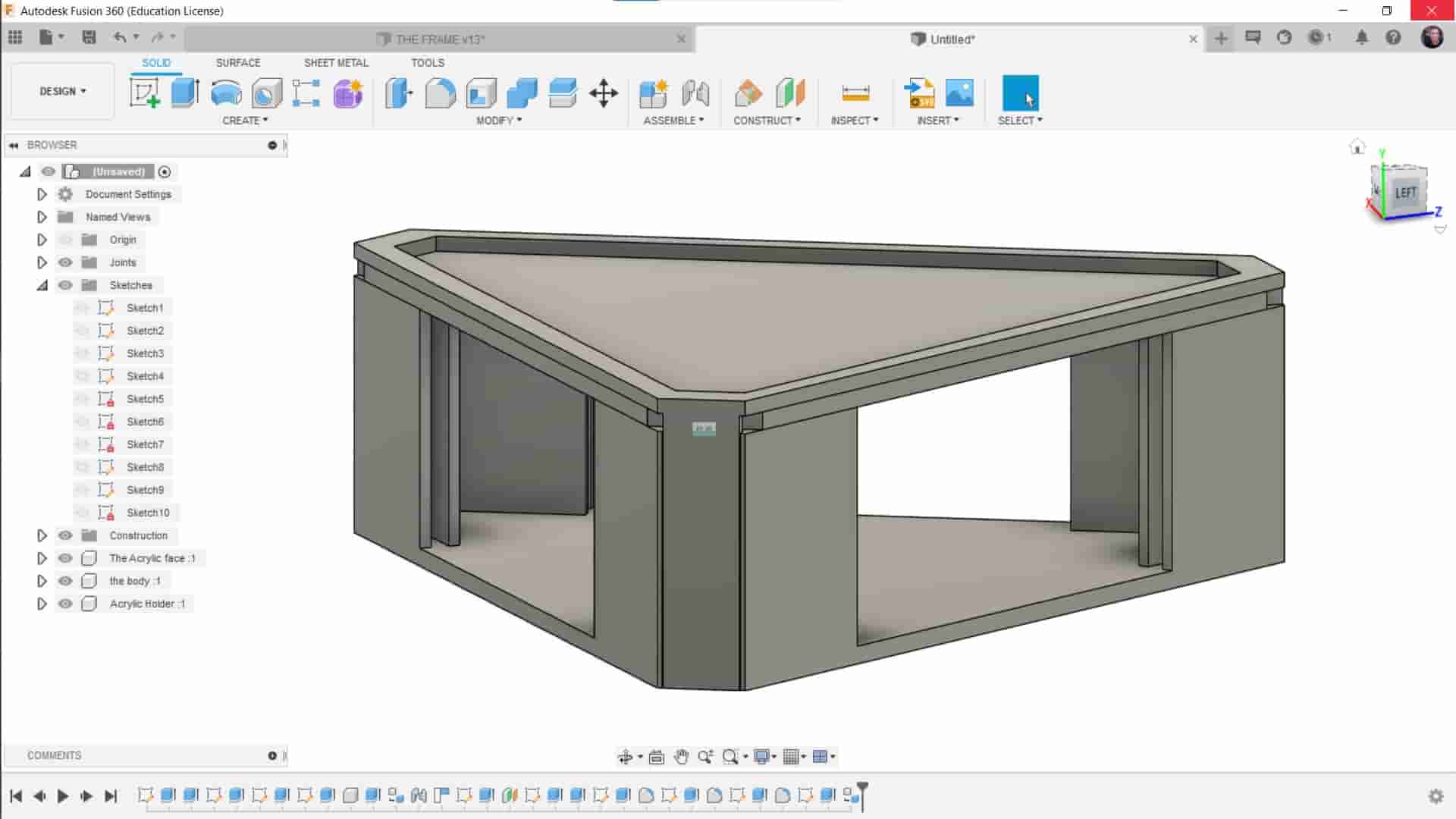
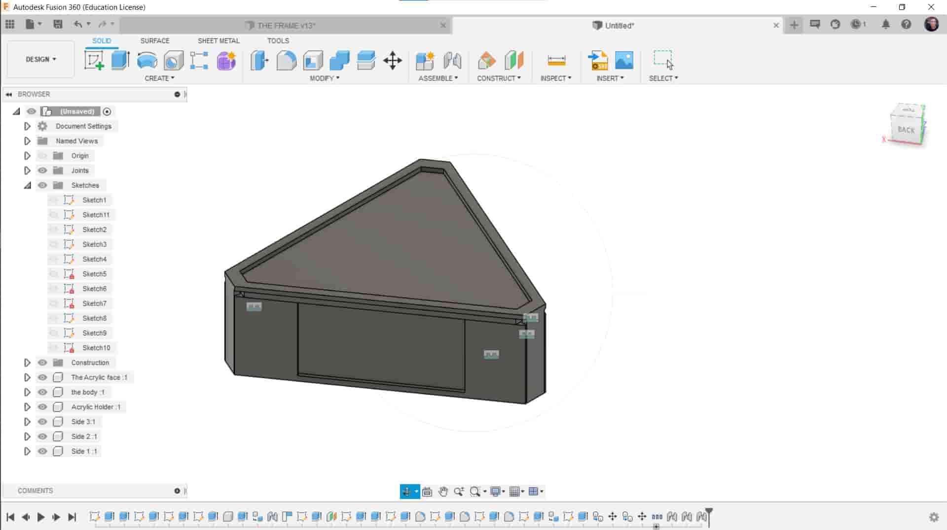
And Then making the top part of our Enclosure and Join it Together
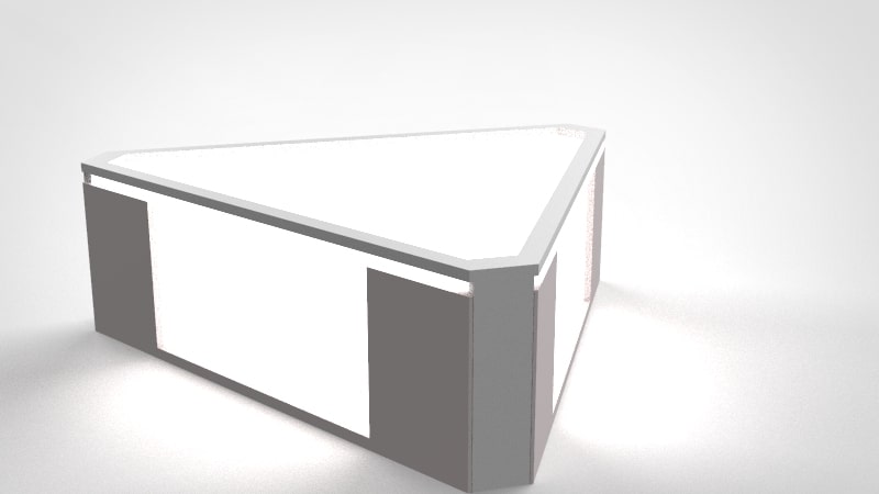
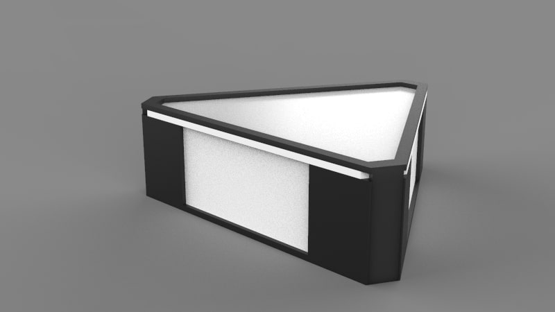
And after Rendering the Project Should Look Like This
Printing And Cutting
After I finished the Design I Sent the Stl File to Prusa Machine To Printed the Enclosure
the Printig Should Look Like This
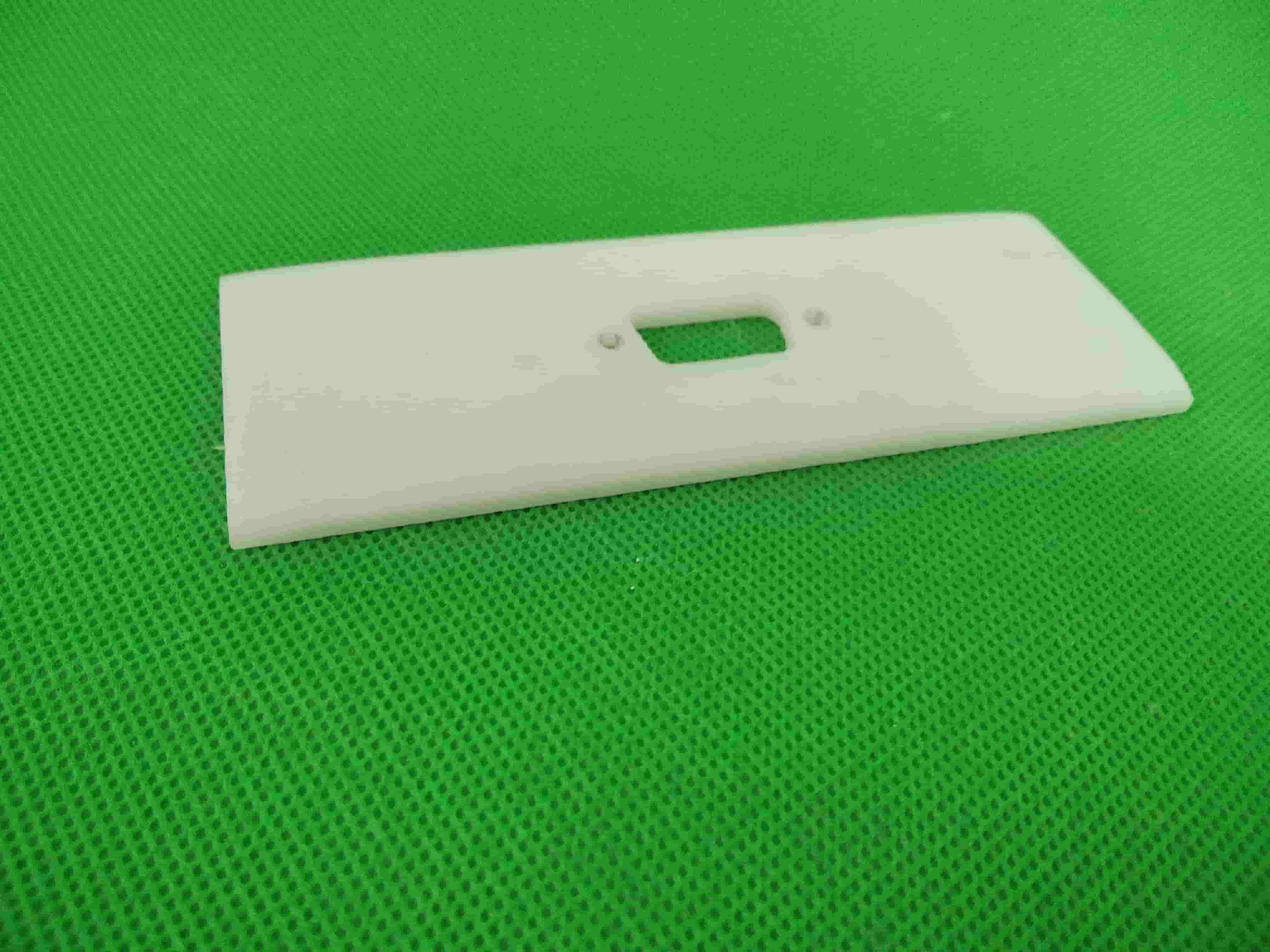
and Now Let's Move to the Acrylic Top and Sides ( as I told You the Liks to all my Designs you will find it Down Below)
I used 3mm White Acrilic To Difuse the Light (If you want to Difuse the Light more Further you can sand it a little )
the Parts are Consists of Top And Side
That's the Top acrylic Difuser

And the Side Part
Outer Box & the Enclosure
After Fabricating all the parts I will Assemble the Design Together
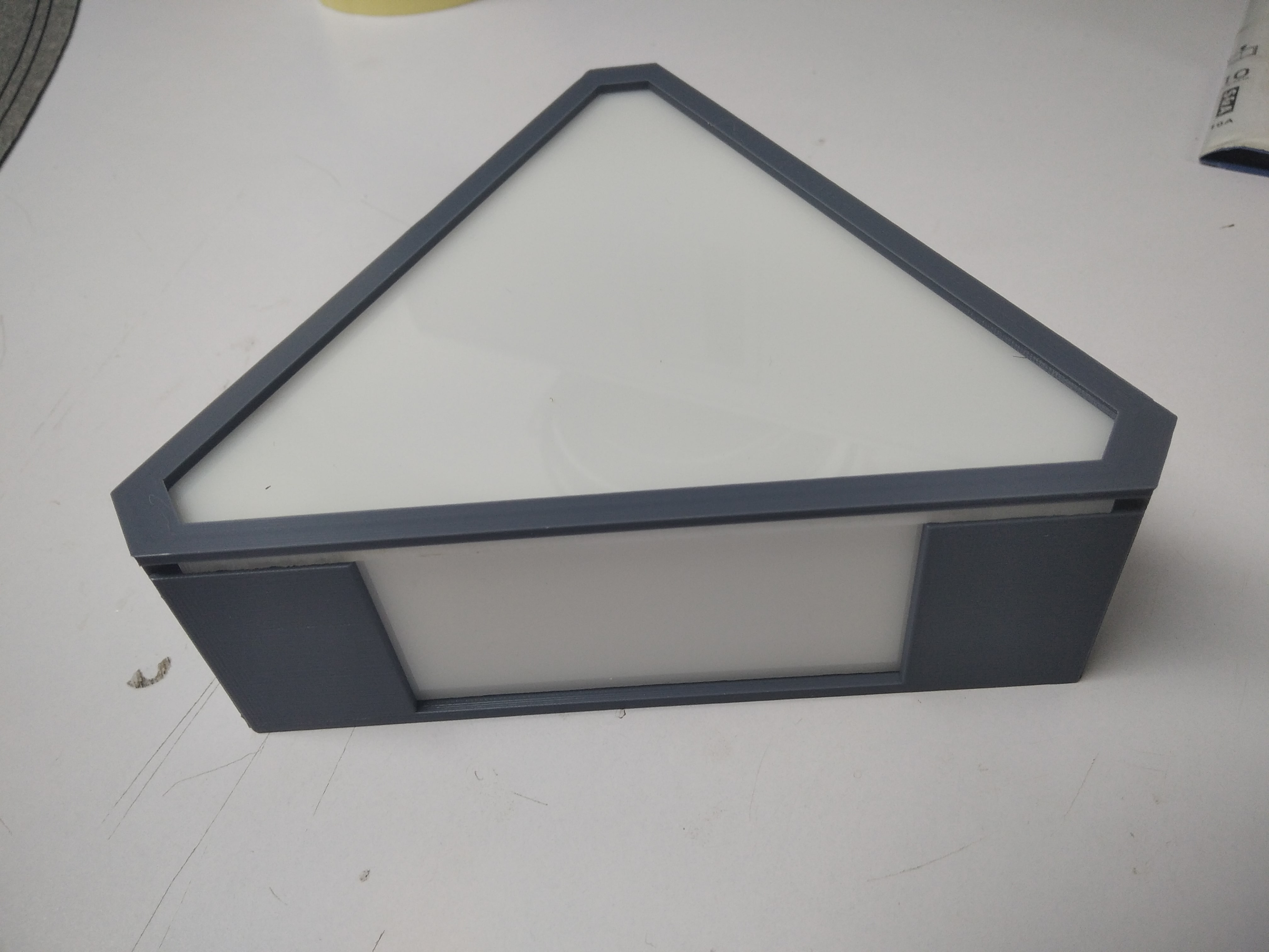
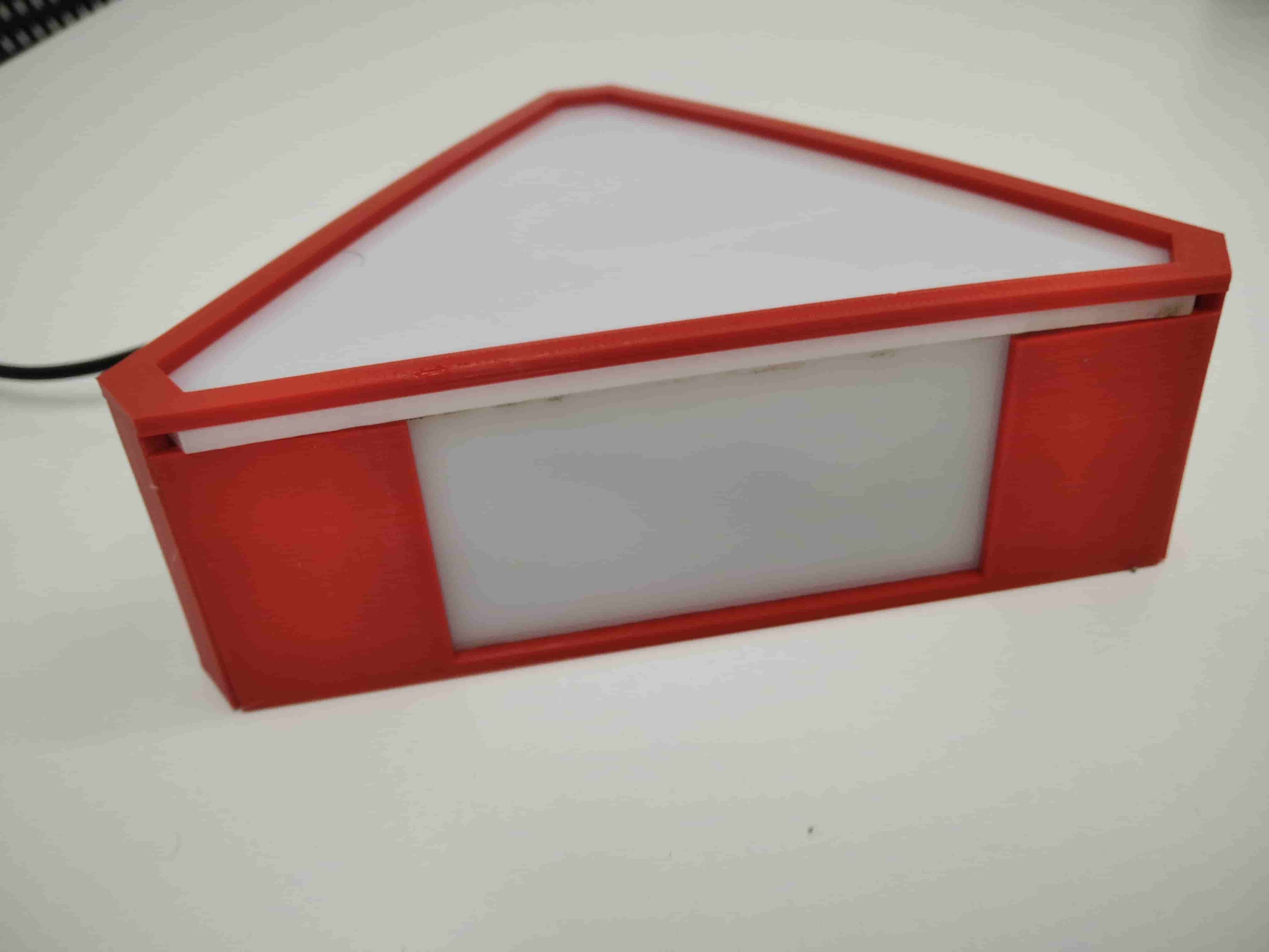
Then I made an Outer Acrylic BOx to Put the Project in it
Don't worry Also I Put the Design of the Box Down Below
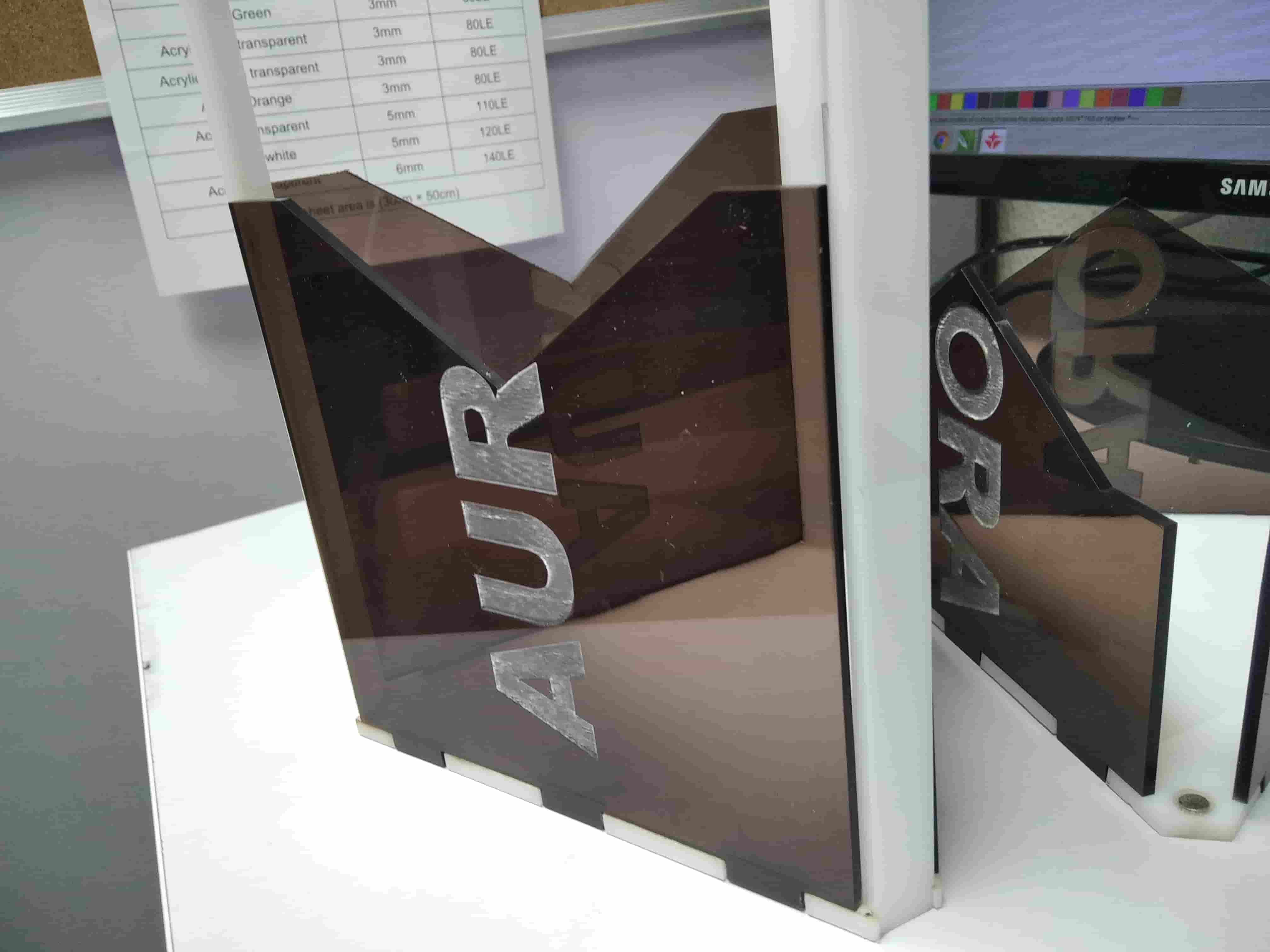
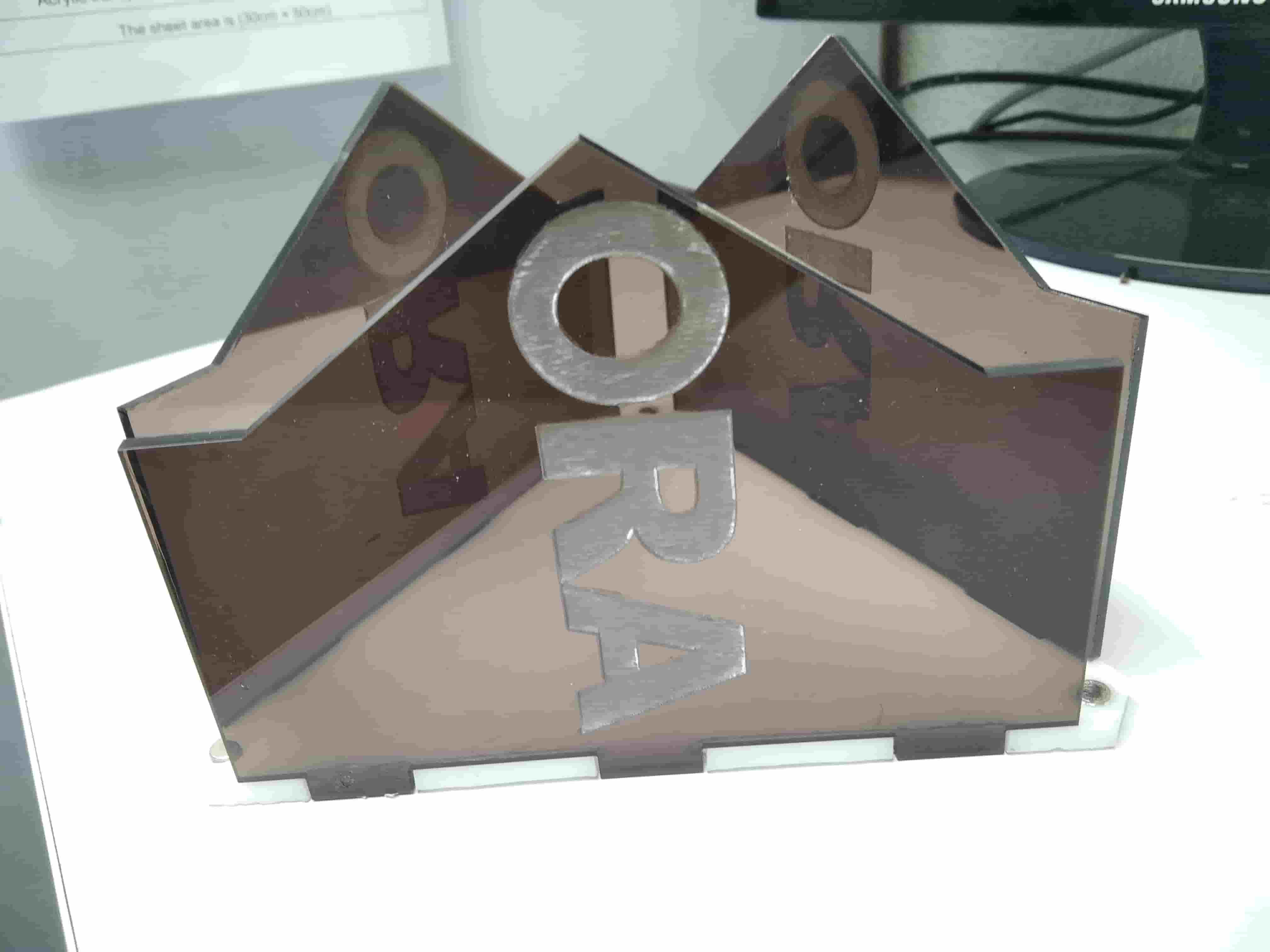
and Let's take a look on the Customer Experience
Electronics Production
Basicly I made Alot of PCB's this Time because There is problems shown in our way so Keep Up With me
PCB V1
What I want From this PCB in this Version is To have A mic in it and also have Separated Parts (Controller & light)
So let's go to the schematic and Mic
So Let's Export As png and fabricate the PCB
Let's Send File To Modela and fabricate the PCB
But Unfortunately This PCB didn't Work For Two Reasons
The First Reason was that the Separte PCB's Was not Quit Effecient
The Second was the the Bluetooth Can't Opearate with out Crystal
So I have to Build Another one
PCB V2
To Prevent More Talking I will Leave the Final Schamatic and board Down
So I made a new Version of my PCB Have Contain Mic And doesn't Contain the Mic
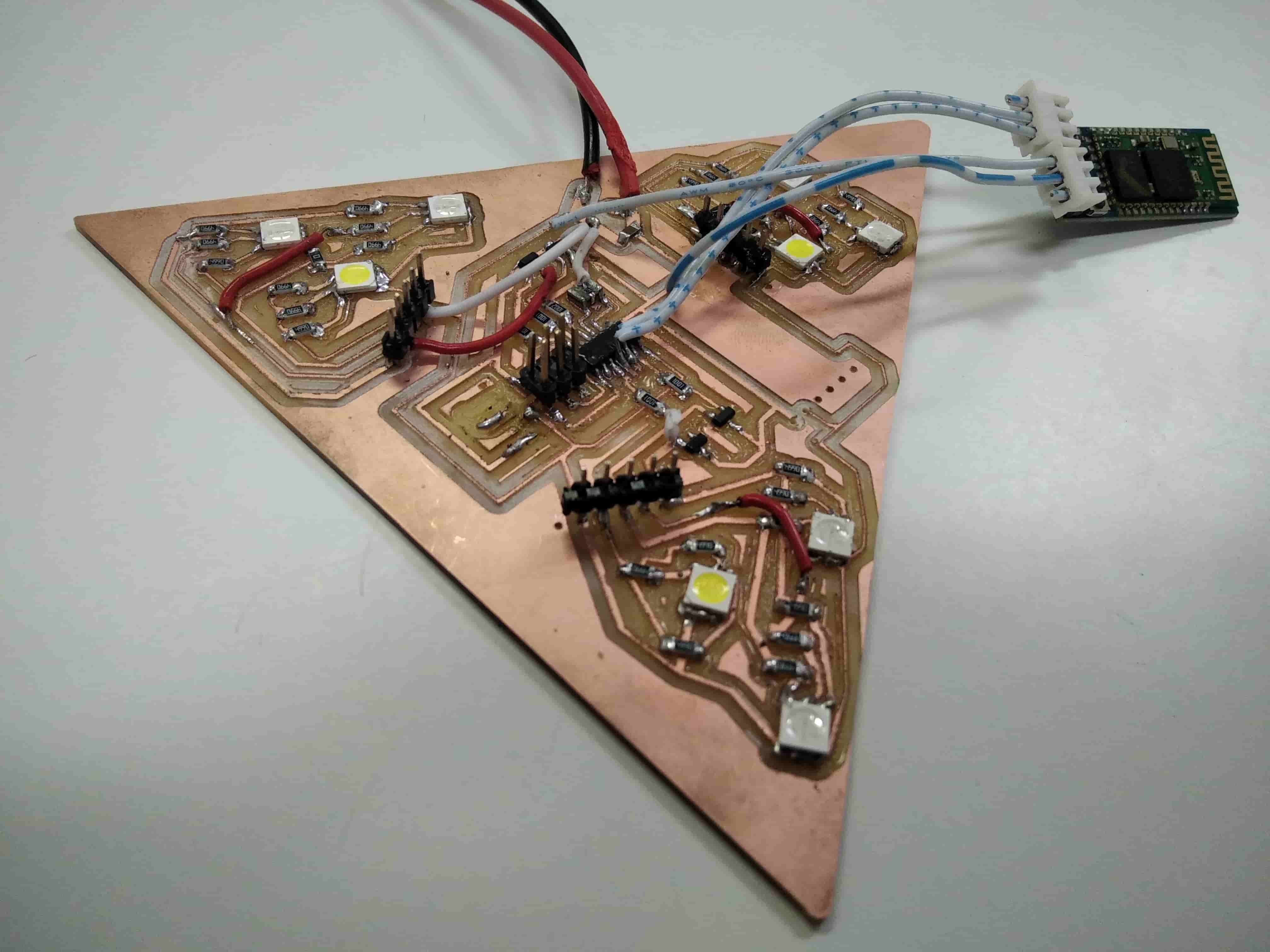
So Let's Solder
Then Let's see the PCB after Soldering
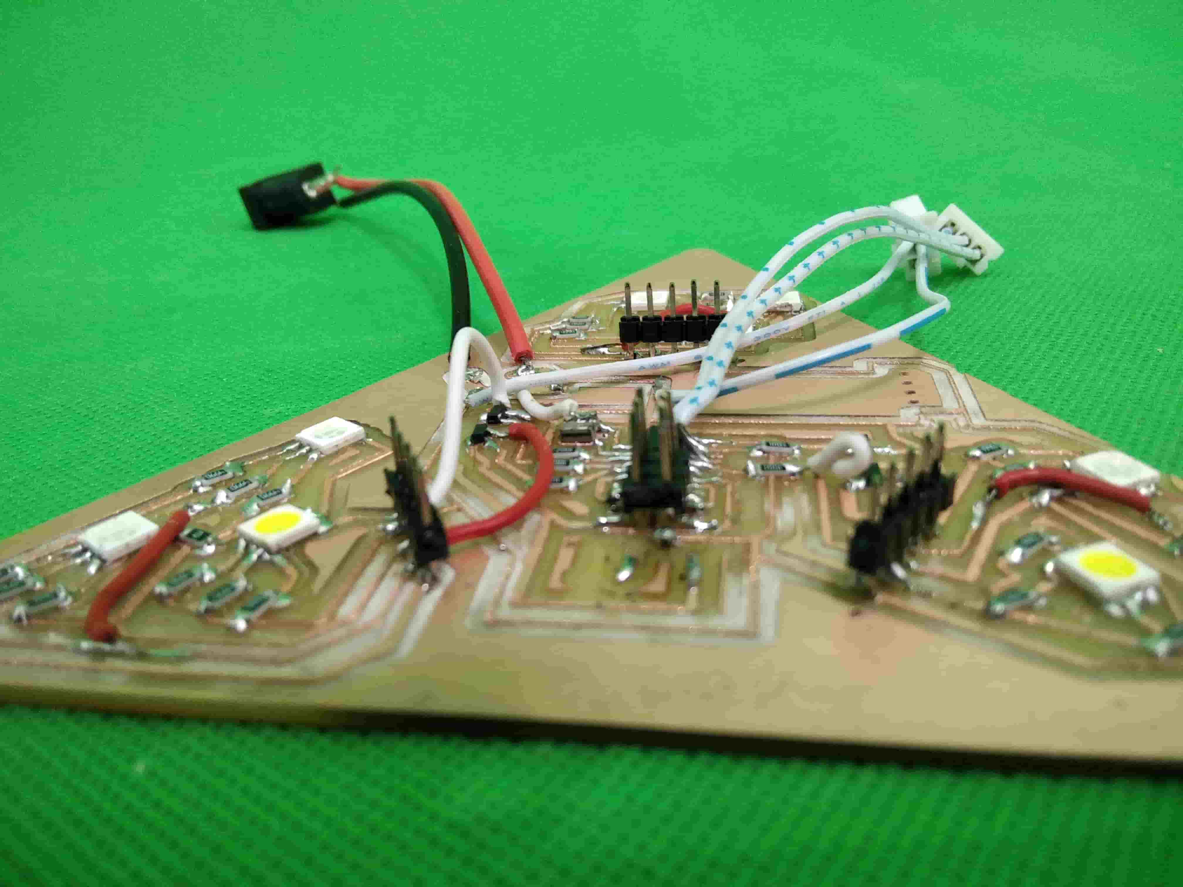
Then Let's Hook the Bluetooth
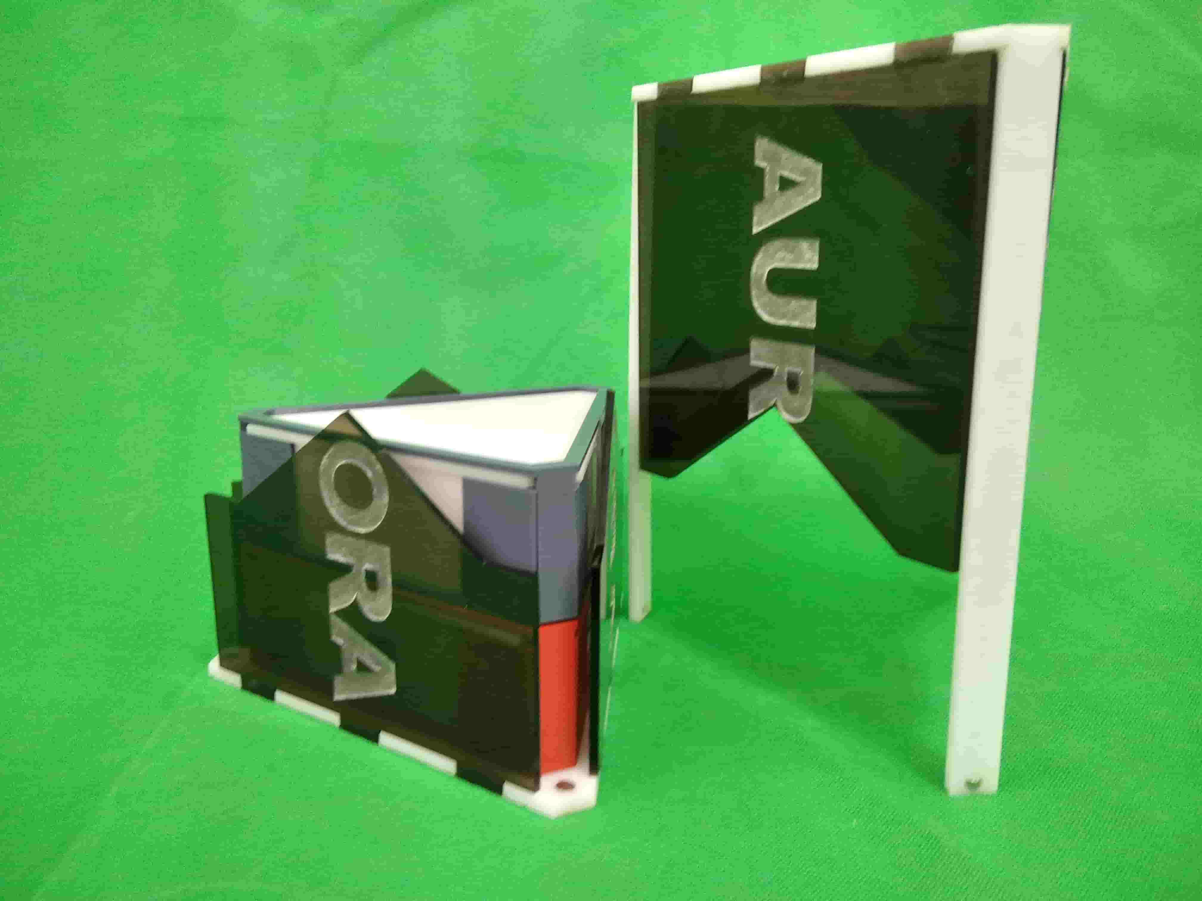
Finalizing
Now Every thing Work just fine, Then Let's See the Result

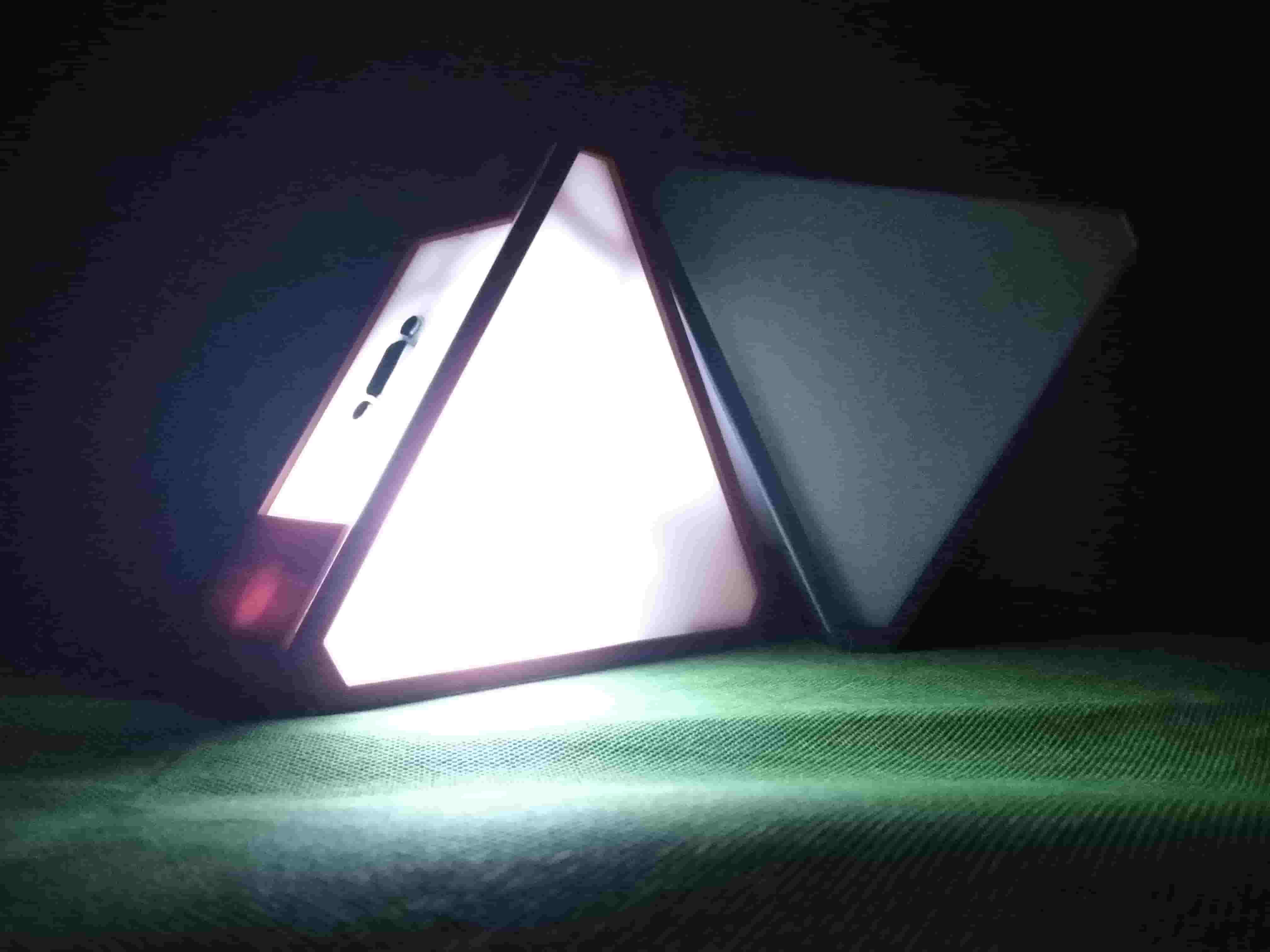
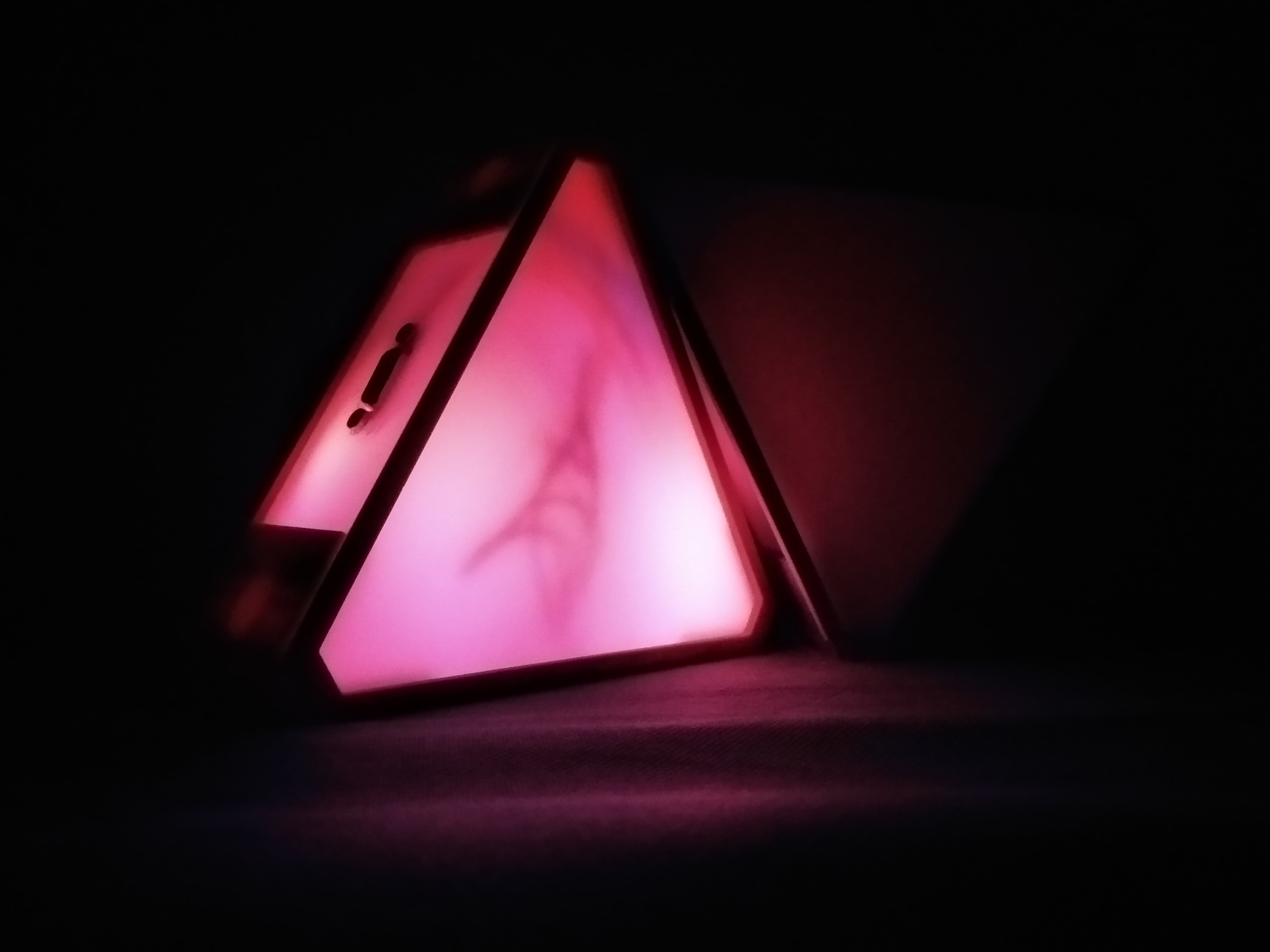
And Here is how the Aurora Work
and Here is the Presentation Video , Cool Isn't it ?!

This work is licensed under a Creative Commons Attribution-NonCommercial-ShareAlike 4.0 International License.
Using the mentioned lisence will make other users able to:
- Copy and redistribute the material in any medium or format
- Remix, transform, and build upon the material
- An appropriate credit must be given to the creator and the lisence
- No commercial use for the material
- Remixed versions must be distributed under the same license as the original
Important Ques?
What's The next step ?
I really enjoyed working on this project and I look forward to:
- Add integration to an existing task management tool
- Add Touch Sensor that's allow to Activiate Aurora BY HAND
- Add Microphone to Interact with Music
- Add More Devices (AURORA Modules)
What Worked what Not ?
Actually as I saied that I want to add A microphone detection with my board So I made the board but Evenually It didn't Work, I think the Problem was in the integration Between boards
How was it Evaluated ?
The Evaluation was According to the Following (The pair minimum Features)
1- Is the PCB Working or Not (Lightning in the Three Diffrents modes) ?
2- The Enclosure Was Finished or Not ?
3- Is the Enclosure used to made it what we learnt in digital fabricaation ?
4- Is it good finish Looking ?
5- Is it meet the pair minimum requirement for a Final Project ?
And the Answer is Yes I passed the Evaluation of the Project and Continue on devolping It.
What are the Impacts of this Project ?
The Importance of this Project are Summarized in three things
1- This Project is Cheapest one in it's Category (The Total project is under 10$)
2- It's the Future of the Light systems
3- The functionalty of the project make it Used in Diffrent setuations Like (Parties-Normal Light's etc.....)
Downloads
Circuit Board
[.sch] Testing_Schematic [.brd] Testing_Board [.sch] AURORA [.brd] AURORAEnclosure
[.stl] Base [.stl] Top_Cover [.dxf] Top_Part_Acrylic [.dxf] Side_Part_AcrylicThe Box
[.dxf] The_Base [.dxf] The_Corner_Stick [.dxf] The_Down_Side [.dxf] The_Top [.dxf] The_Upper_SideCode
[.ino] Blinkin [.ino] Bluetooth_Code [.aia] App_Inventor_Appication