12. Output devices
INTRODUCTION
This week I had to make a board with an output device on it. At first I tried to control the servo motor using an arduino, then I designed a board with an RGB LED on it (using Neil’s board example) and added an input device on it, to control output device with the input device (a potentiometer).
ARDUINO + SERVO + POTENTIOMETER
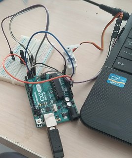
For this stage I just used an arduino UNO, connected it to a servo, and a potentiometer, using a breadboard, here is the setup.
Then I uploaded the code knob from arduino code examples
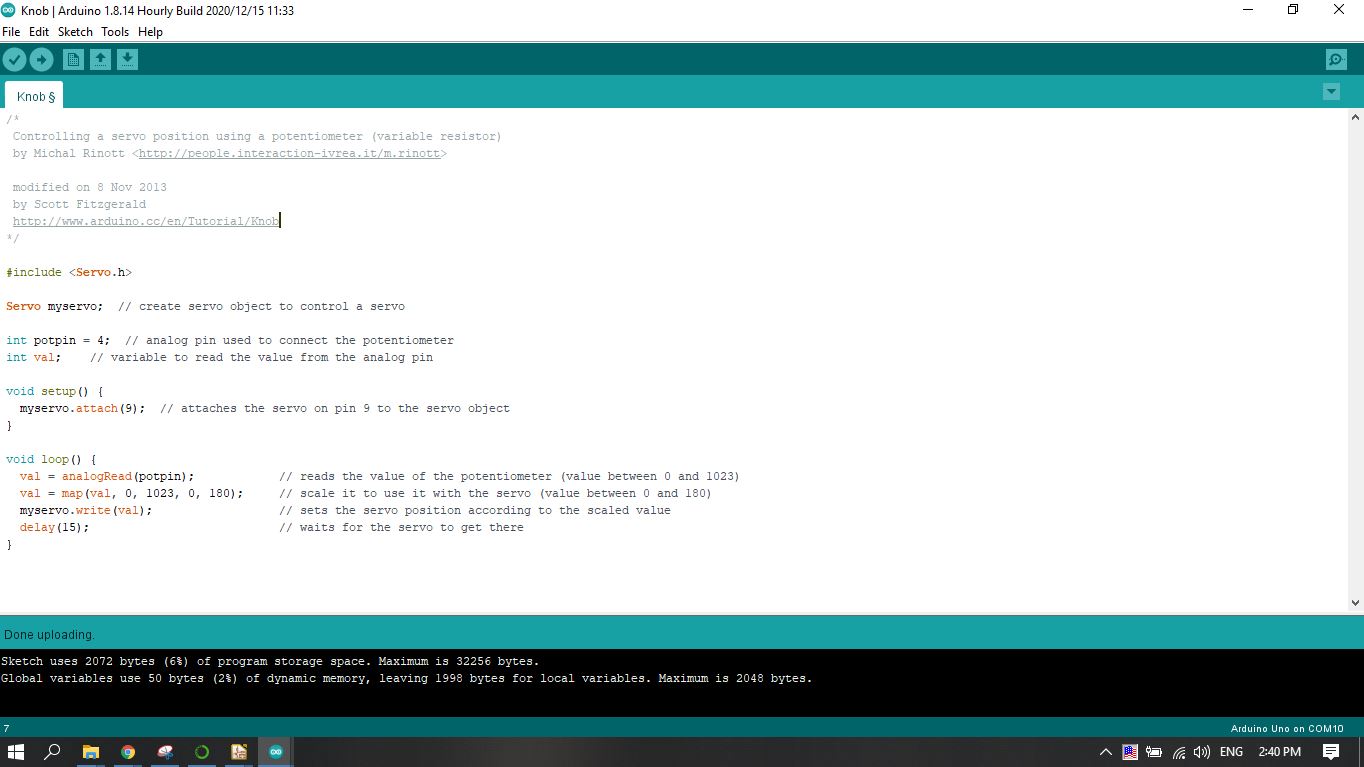
And it worked, as I am rotating the potentiometer, it changes the value of input and it changes the output value, which corresponds to the position of the servo.
DESIGNING BOARD
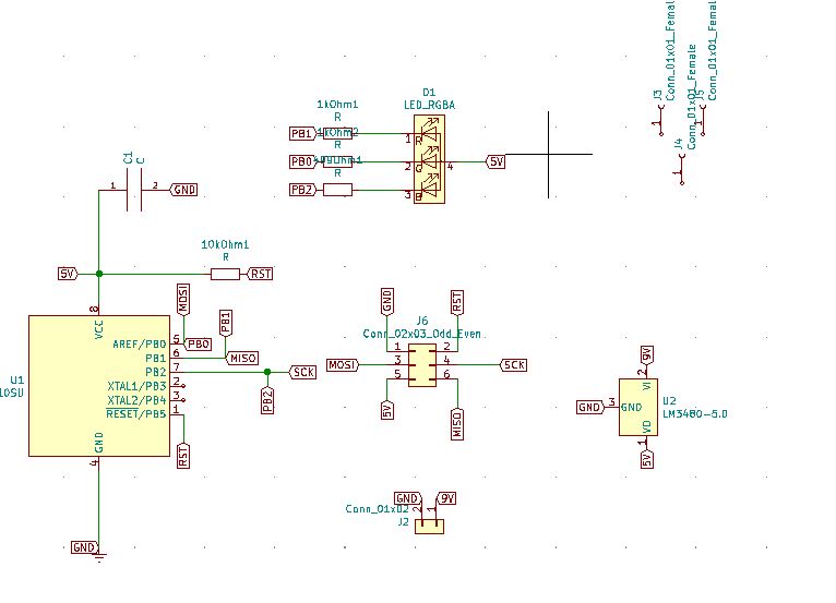
After that I started designing a board with AtTiny45 and RGB LED. For that I used the RGB 45 board. I changed the design in some places, for example there was no reason to use 4 pins pin header for power input, instead of that I used just 2 pins.
Then I added the footprints and made the connections.
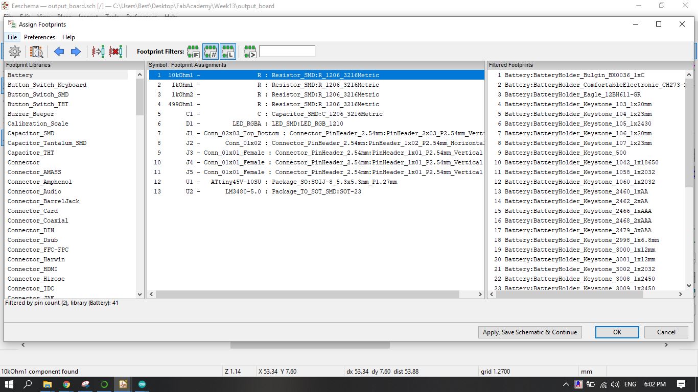
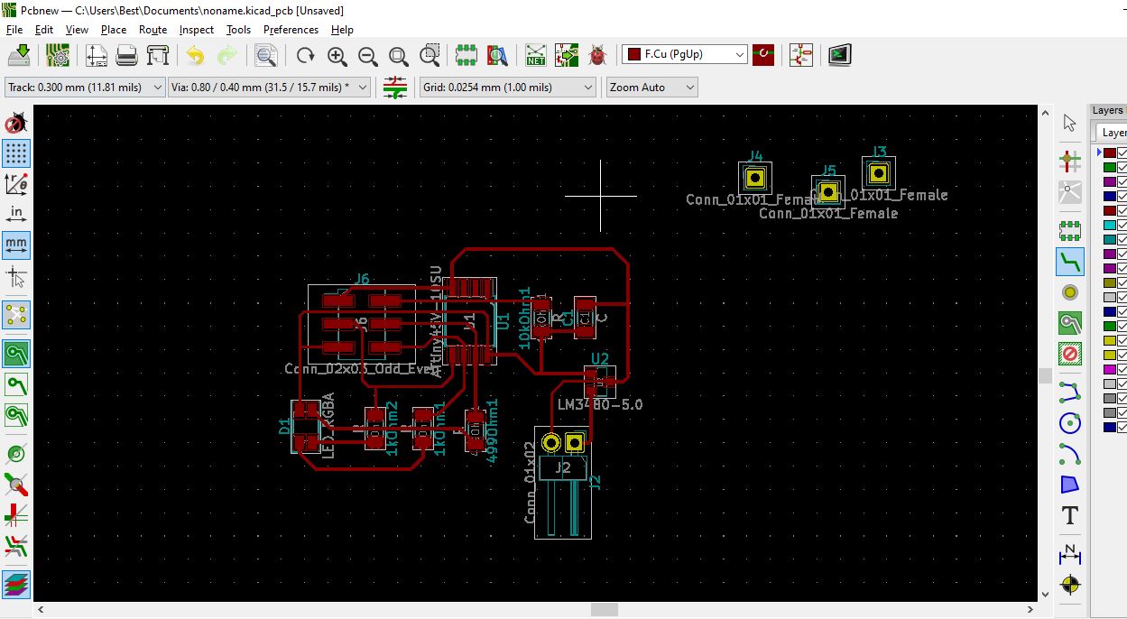
I also added the potentiometer. There was no footint for the potentiometer that I had, so I manually measured the distances and placed the footprints.


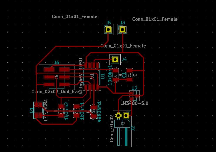
And this is the final design
MILLING
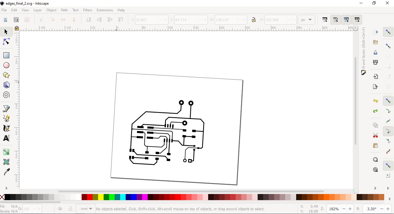
After exporting the file from KiCad as SVG, I opened it with Inkscape, to prepare traces and edges for final steps. Then I saved the final SVGs.
Then I used Fabmodules to generate G code to mill the board with Roland SRM20.
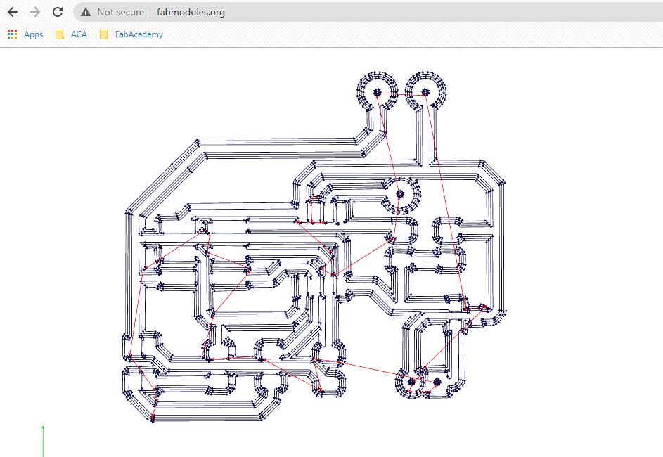
These files are listed in the end. Then I started milling, with 1/64” end mill for traces, and 1/32” end mill for edges and trough holes.

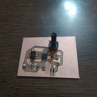
Then as always, comes the soldering part, which is my favorite. And after soldering all the components, here is what my final board looks like.
PROGRAMMING
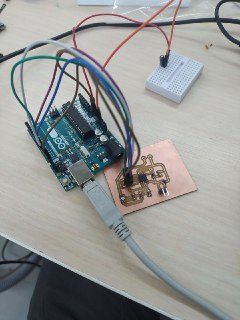
I decided to program my board using an arduino, because it’s much faster for me. Although, there is no difference in this case, because I’m not using any special library from the arduino in the code (as you can see below), and the microcontroller can be programmed with FabISP using exactly the same code. To program the AtTiny45 I followed all the steps from my documentation of embedded programming. Here is the setup.
At first I just uploaded Neil’s code of RGB board, just to check if everything works fine.
Then for the potentiometer, I decided to just change the colors of the RGB LED from red to green to blue with some time delays, where the delay time is the input value of the potentiometer. Here is the code.
int red_light_pin= 1;
int green_light_pin = 0;
int blue_light_pin = 2;

int pot_pin = 3;
int pot_val = 0;

void RGB_color(int red_light_value, int green_light_value, int blue_light_value)
 {
  analogWrite(red_light_pin, red_light_value);
  analogWrite(green_light_pin, green_light_value);
  analogWrite(blue_light_pin, blue_light_value);
}

void setup() {
  pinMode(red_light_pin, OUTPUT);
  pinMode(green_light_pin, OUTPUT);
  pinMode(blue_light_pin, OUTPUT);
}

void loop() {
  pot_val = analogRead(pot_pin);
  RGB_color(255, 0, 0); // red
  delay(pot_val);
  RGB_color(255, 0, 255); // green
  delay(pot_val);
  RGB_color(0, 0, 255); // blue
  delay(pot_val);
}
And after uploading, it worked just as needed.