5. Electronics production
INTRODUCTION
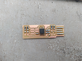
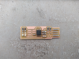
This week I had to make this in-circuit programmer by milling and stuffing the PCB.
MILLING
To cut the PCB I used Roland mono-fab SRM-20, and here is it’s manual.
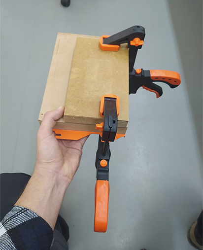
At first I took the table (which is a piece of wood, meant to be placed under the board, and so the mill bit will cut the table, and don’t ruin the mill bit) out from the machine by unscrewing 4 screws around the table. Then I attached the board to the table using double sided tape. After that I used clamps, to fix the board in place, and let it under pressure for about 15 minutes.
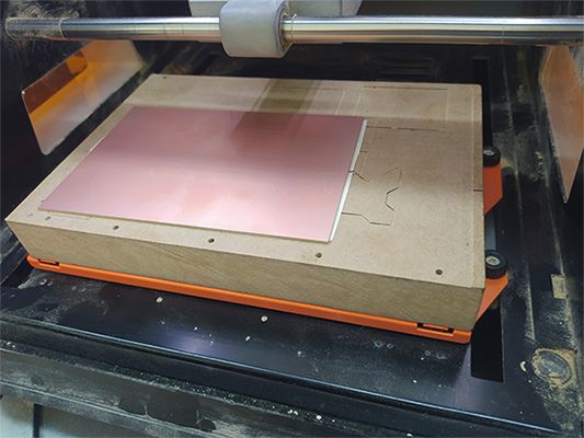
After that, when the board was securely attached to the table, I installed the table back in the machine, and tightened the screws.
Then I had to install the mill bit. At first I will cut the traces of PCB, then the outline.
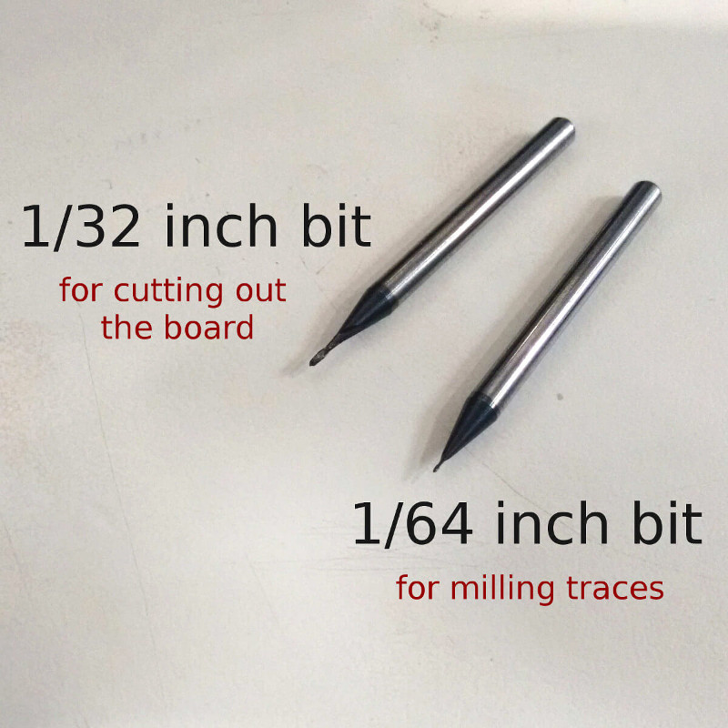
As for cutting the traces we are using 1/64” mill bit, I installed it in the machine as shown in the 86th page of the manual.
For milling the traces we are using smaller end mill than for cutting the edges, beacause for traces are thin, and we need as much precision as we can have. On the other hand, when cutting the edges, endmill has to take more preasure, and we don’t need as much precision as with the traces, so we are using 1/32” end mill.
After installing the mill bit, I had to the G-Code corresponding to the traces of the PCB. To generate G-code, I used fabmodules. Just uploaded the .png file and set the settings as shown below
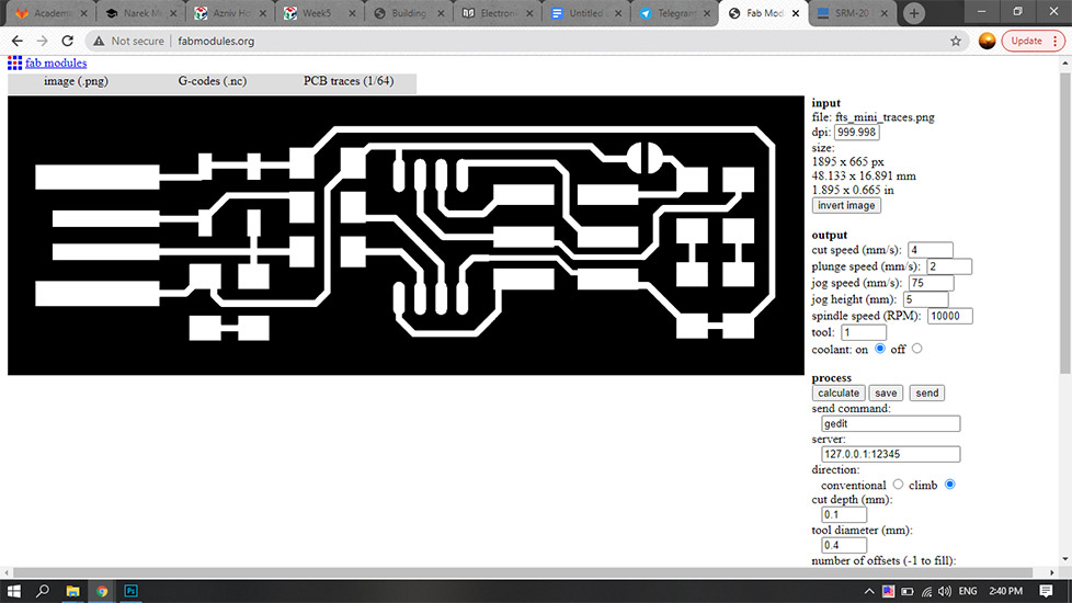
Then click calculate, and download. Now it’s time to turn on the machine and open the software.
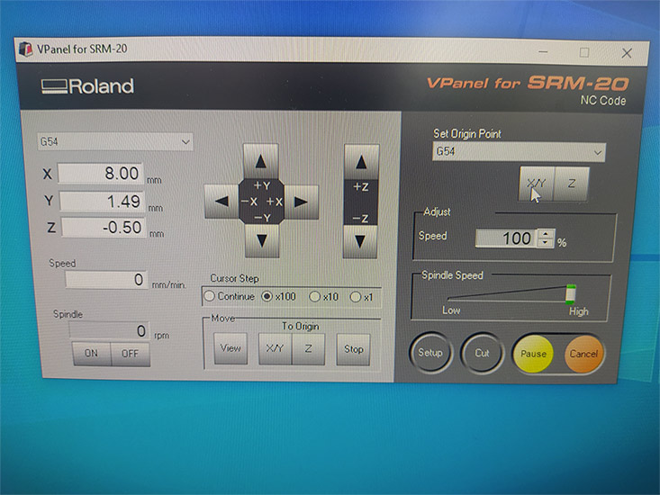
In the G-Code generated by Fab Modules, there is a line in which you can find G54. That line corresponds to the coordinate system that machine is going to use. In the picture above you can see that in the software it is set to G54. In most of the cases, G54 is the default coordinate system, but if you want to use another one, or use 2 or more different systems, you can easily change it both in the software and in the G-Code. Then I moved the mill bit to the corner of the board, and set the origin of XY there using the “X/Y” bottom on the right. After that I decreased the Z coordinate, until about 1sm above the board, then I released the mill bit while supporting it with a finger, after it touched the board, I retightented it. Then I set that point as origin using the “Z” bottom on the right. This whole process is shown in the 91th page of the manual (in this step I had to be careful more than usual, because 1/64’’ is very small and easy to break). Then I imported the G-Code file into the software and started milling.
Then I changed 1/64 to 1/32, repeated this whole process to cut the outline, using this .png file.
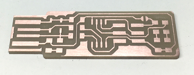
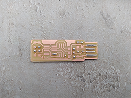
Here is what I got
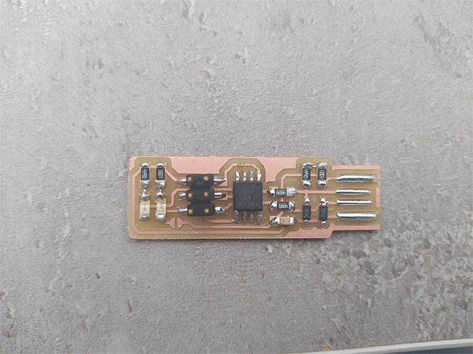
SOLDERING
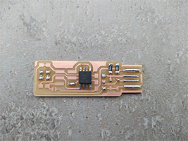
I had some experience of soldering, so after I got the board, I started soldering right on. Here are all the components that are used on the FabISP 1x ATtiny45 2x 1 kOm resistors 2x 499 Ohm resistors 2x 49 Om resistors 2x 3.3V diodes 2x LED 1x 100 nF capacitor 1x 2x3 pin header
Programming
I had a problem at this stage, I couldn’t program my board, and I had very limited time. I headed back to my city, next week I will figure out what was the problem, and maybe make a new board and program it.
UPDATE
I had to make a new FabISP, beacuse I figured out that lat time I put both LEDs in wrong direction, and instead of fixing them, I made a short in the circuit and porbably burned the AtTiny45. So I repeted all the process above.
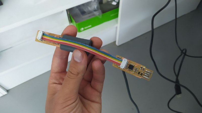
My computer works on Windows OS, so I decided to continue and do the programming part in the lab using linux, because on linux it’s easier to use AVR programmer. I did all the process following brians documantation, which is very usefull and nicely written. The computer in lab already had the software installed, so I just needed to download the code and makefile, and run them after connecting programmer to the computer. To programm my FabISP I used Babken’s FabISP. Here are the connections for programming steup, just connect FabISPs to each other, and connect each of them to the computer.
As I was using a programmer from usbtiny family, I didn’t have to change anything in makefile. If you are using other programmer, you have to change the name in makefile accordingly (for example Maro used AVRISP2 programmer, you can find detailes in her documentation). Than run make flash. This will erase the target chip, and program its flash memory with the contents of the .hex file you built before. You should see several progress bars while avrdude erases, programs, and verifies the chip. Than run the make fuses command. This will set up all of the fuses except the one that disables the reset pin. Again, you should see several progress bars from avrdude. After this steps, you have to make sure, that your FabISP works, by programming other board (your friend’s FabISP). I programmed a board, that was in Dilijan FAB lab and needed to be programmed for a project. After making sure, that everything works as needed, you can lock the code inside the AtTiny45 bay running command make rstdisbl. From that point on, you can’t change the code inside that AtTiny. So now you have your own ISP.