11. Input devices
INTRODUCTION
This week I had to design and make a board with an input device on it. I decided to go with an ultrasonic sensor. I designed and programmed a board that measures the distance and alarms you when you are too close to something. This is like a parktronic system.
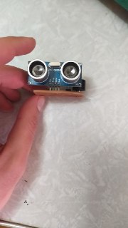
ULTRASONIC SENSOR
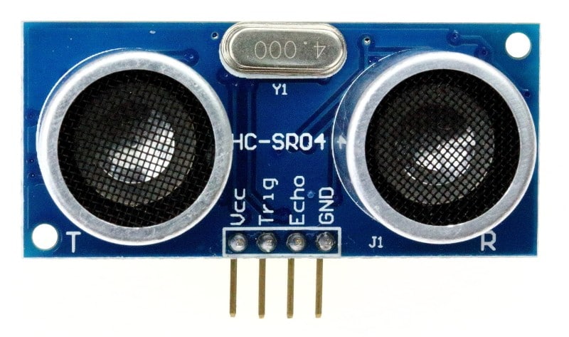
Ultrasonic sensors emit a very high frequency sound, so people can’t hear that. After sound is being reflected from an object it comes back and sensor receives the sound wave, after that we program a microcontroller to measure the distance using time between emitting and receiving the sound. Here is how the code looks like
#define echoPin 2 // attach pin 2 to pin Echo of HC-SR04
#define trigPin 3 //attach pin 3 to pin Trig of HC-SR04
long duration; // variable for the duration of sound wave travel
int distance; // variable for the distance measurement
void setup() {
 pinMode(trigPin, OUTPUT); // Sets the trigPin as an OUTPUT
 pinMode(echoPin, INPUT); // Sets the echoPin as an INPUT
 Serial.begin(9600);
}
void loop() {
 digitalWrite(trigPin, LOW); // Clears the trigPin condition
 delayMicroseconds(2);

 digitalWrite(trigPin, HIGH);// Sets the trigPin HIGH (ACTIVE) for 10 mcs
 delayMicroseconds(10);
 digitalWrite(trigPin, LOW);

 duration = pulseIn(echoPin, HIGH);  // Reads the echoPin, returns the sound wave travel time in microseconds

 distance = duration * 0.034 / 2; // Calculating the distance

 Serial.print(distance);
 Serial.println(" cm");
}
pulseIn() function works on AtTiny microcontrollers as well as on Arduino, so I had no problem using it on AtTiny45.
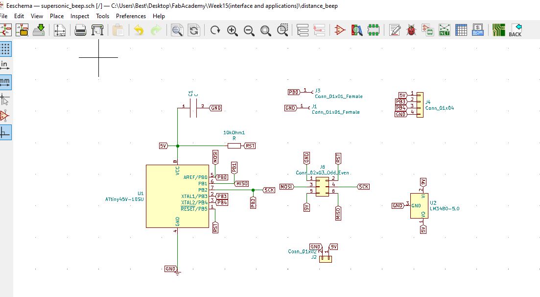
DESIGNING THE BOARD
My Idea was to use an ultrasonic sensor and buzzer on the board and connect it to the battery. So I had to use a voltage regulator which converts 9V DC to 5V DC, because AtTiny45 works with 5V DC. After choosing all the components that I need and connecting them, here is my schematics.
After this I started placing the components with their footprints on the plane.
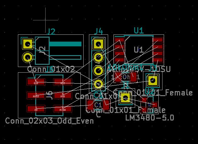
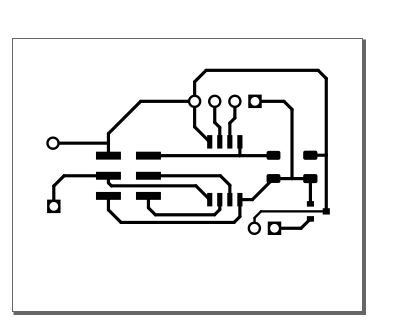
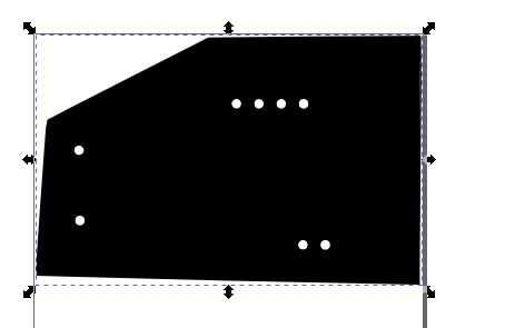
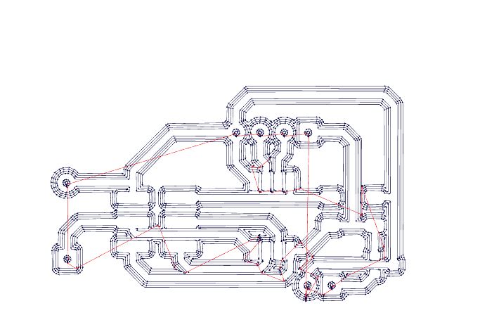
I couldn’t find the footprints for the buzzer, so I had to place 2 holes manually. I placed the ultrasonic sensor so it faces outside of the board. For power input I just used 2 pins with through holes. After connecting all the traces and drawing the outline of the board, here is what I ended up with.
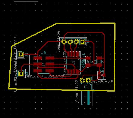
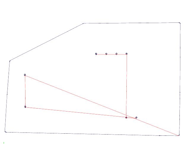
After exporting and post processing in inkscape, here are the traces and outlines of the board.
MILLING AND SOLDERING
After having this SVG files, I used fabmodules to generate the toolpath for Roland SRM20 milling machine.
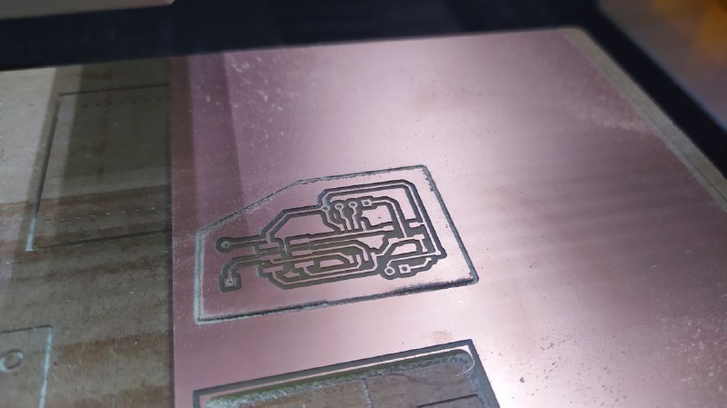
So I first used 1/64 end mill and milled the traces of the board, then I changed the end mill, put 1/32 and cutted holes and outlines of the board. Here is the board after milling.
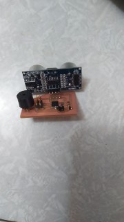
After soldering I had the final version of the board with components.
PROGRAMMING
I decided to have 5 different modes for my parktronic. If the nearest object is further than 2 meters then it doesn’t beep. If the distance is between 1 meter and 2 meters, then it beeps slowly. If the distance is between 50sm and 1 meter, it starts beeping faster. If the distance is between 30sm and 50sm, it beeps even faster. And finally if the distance is less than 30sm it beeps very fast.
I wrote code using Arduino and uploaded on my AtTiny45. You can find the code in the end of the page.
And this is the final board in action.