3. Computer Aided design
INTRODUCTION
This week I had to play with some modeling softwares, find which of them work for me the best. I tried Adobe Photoshop and GIMB for working with raster files, Adobe illustrator and Inkscape for working with vectors. And for 3D modeling I tried Free Cad, as it’s a powerful open source software. But later on, when I have a licence, I will try and learn Fusion 360 as well.
Vector and Raster
I had a rough idea what Vector and Raster are, but I did some research to understand them deeper. So the main difference is that you can zoom in Vector files as much as you want without losing quality, but if you zoom in Raster file, you will lose quality of your image. The reason is that Vector files are made out of points and mathematical functions to join that points, so zooming in and out has no effect on quality. On the other hand, Raster files are made out of pixels (pixel is a tiny square which has some color), and if you zoom in too much, you will start noticing each individual pixel. Advantage of a Raster file is that it’s more detailed.
If you want a Raster file, you have to work with .jpg, .png, .psd, .gif formats. If you want a Vector file, you have to work with .ai, .pdf, .svg formats.
Here is a good video on this topic.
Vector
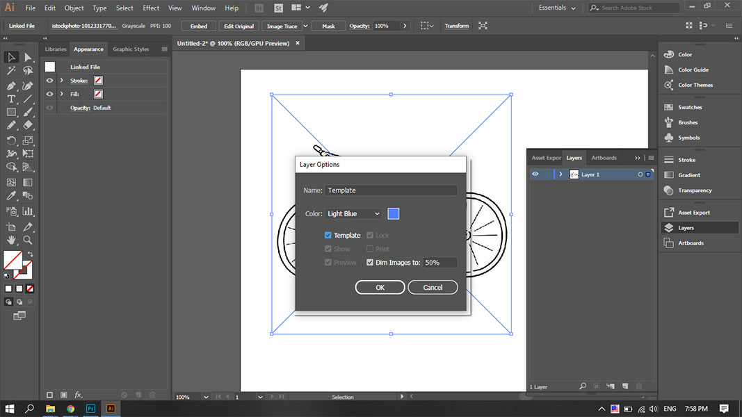
I decided to try out Adobe Illustrator and Inkscape to work with vector files. At first I went for Illustrator. I downloaded a photo of a bike from the internet, made it a template in Illustrator as shown below.
Then I started drawing a vector image of that bike using the Pen Tool, after that I colored some areas. To mark those areas, Shaper tool is a very good tool. And here is what I got.
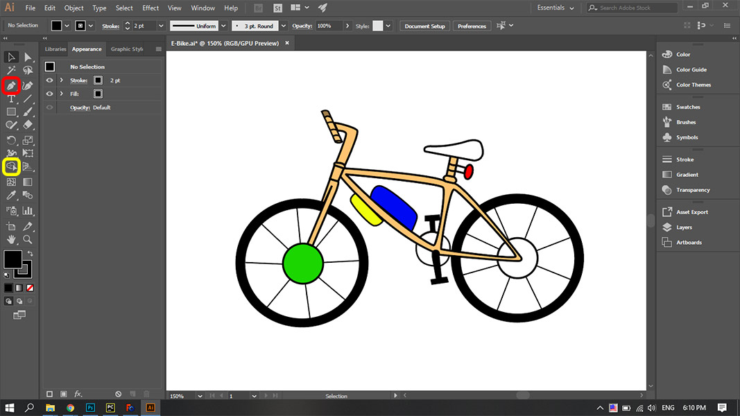
Downloadable file of this vector Vector Bike in Illustrator
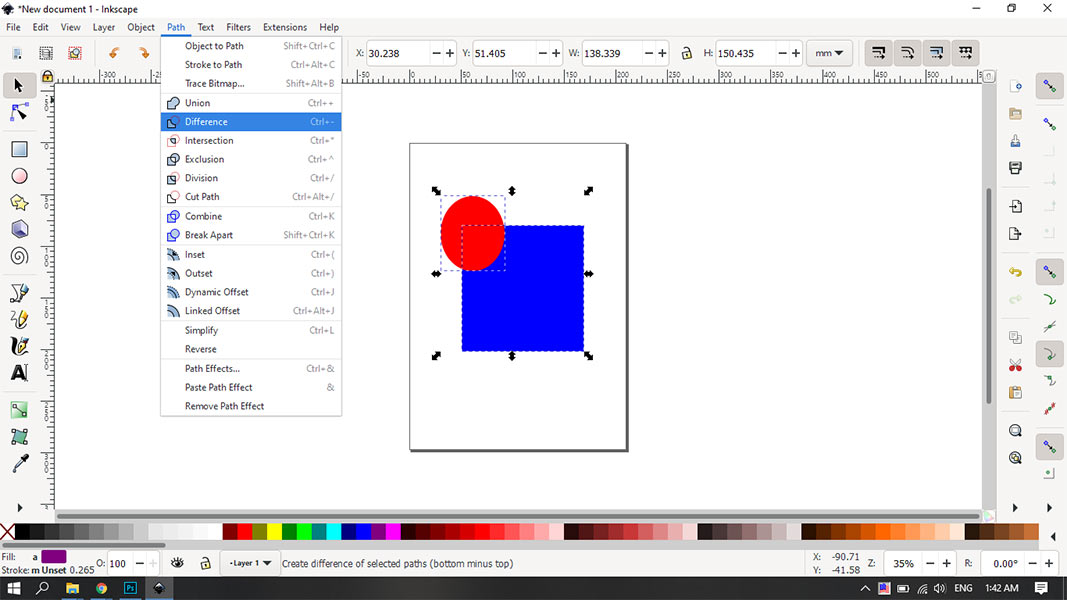
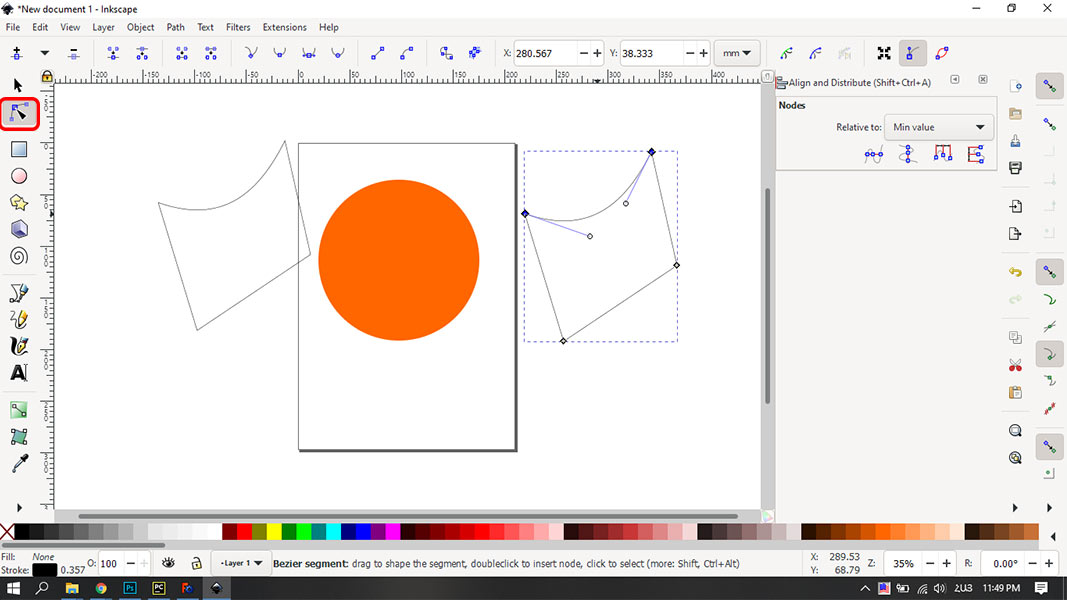
Then I downloaded Inkscape and started playing with it. I tried subtracting two objects from each other. It’s a straightforward operation and a very useful tool. It’s shown below.
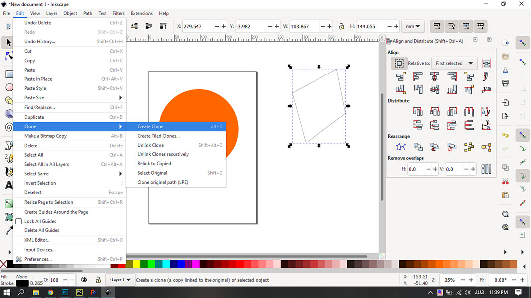
Then I used the pen tool and drew a random quadrilateral, then made a clone of it. The cool part of cloning is that when you change your object parameters, the clone changes as automatically and always has the same parameters as the original shape.
Path editor by nodes (shown below at the left) is a very comfortable and easy to use tool for editing curves drawn earlier.
3D modeling
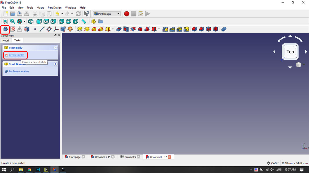
At first I downloaded Free Cad. I found a very good tutorial and followed step by step to make something and get used to tools. I opened the software, chose the Part Design option from the top bar and created a new file. Then I created a new body and a new sketch as shown below.
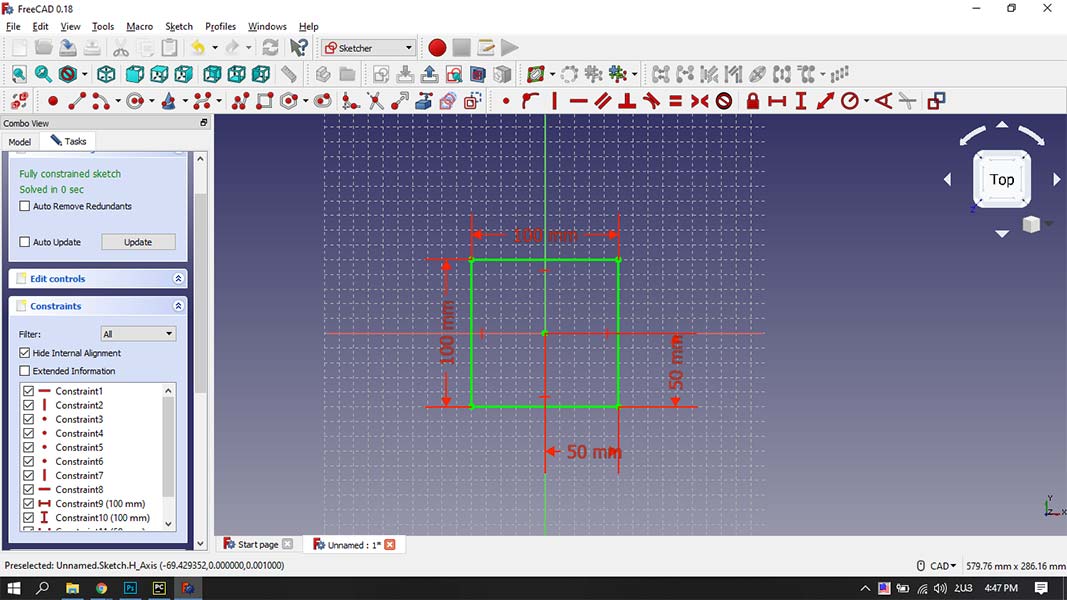
Then I chose XY plane to make a sketch on it. Here I made a square using the line tool and some constraints. As you can see I fixed the horizontal distance between vertices, vertical distance between vertices and distance between vertices and origin point as well. From now on my sketch is fixed on the XY plane.
Then I started to make a 3D shape using that sketch. Padding tool is the easiest way to do that. So I made a cube out of that square, then on one side of that square I made a sketch of a circle, and pad it as well.
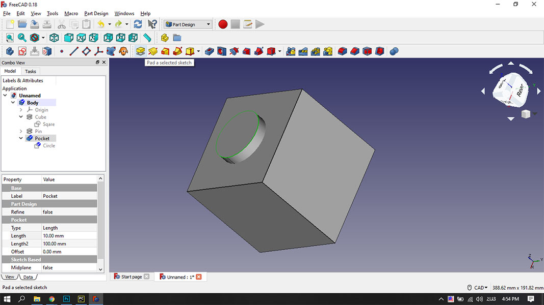
And I made a sketch of a circle on the opposite side or the cube as well, but this time I made a pocket from that circle inside the cube.
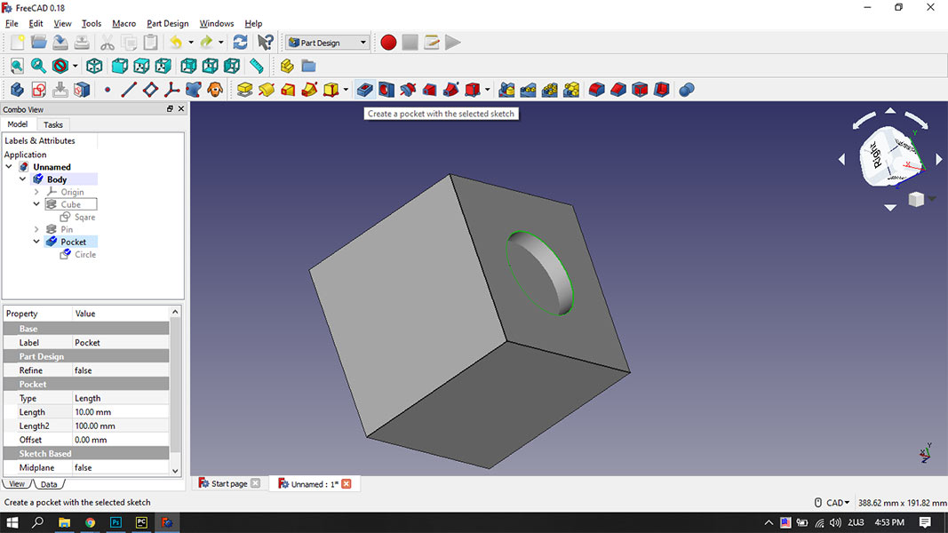
Then I rounded the edges of the cube with the Fillet tool. Now I have a cube with a circle pad on one side and with a circle pocket on the opposite side with the same sizes. So for example if I 3D print a few of this body, I can join them together and get a long something.
Parametric
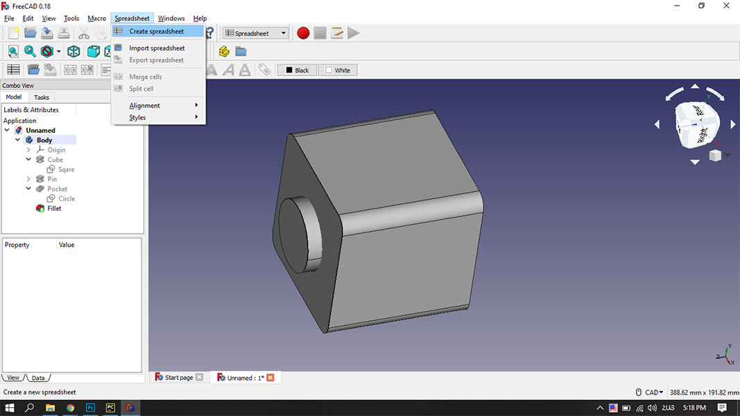
But what if I want to change the size of this whole thing? I have to go through each sketch and change the parameters of each part individually. To avoid that, I found out that most 3D modeling softwares have an option to make the model parametric. What does that mean? Basically, making a parametric model means that you can write down the parameters of the model in some sheet, and then when you want to change some parameter of the model, you just change the corresponding number in that sheet, and your model changes accordingly. To make a sheet like that, you had to choose the spreadsheet option from the top bar and click “Create new spreadsheet”.
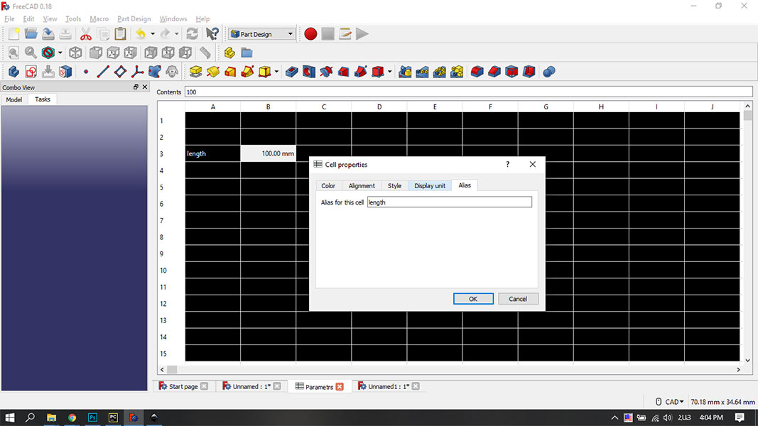
Then you have to type the parameters you want, right click on the cell, give it a name and unit. In this case I named it length and gave it value 100mm.
Then when you go to your sketch you can change any parameter you want and give it a value from your spreadsheet like so. (In this case I named my spreadsheet “Parameters” and the value “length”, so I will type Parameters.length)
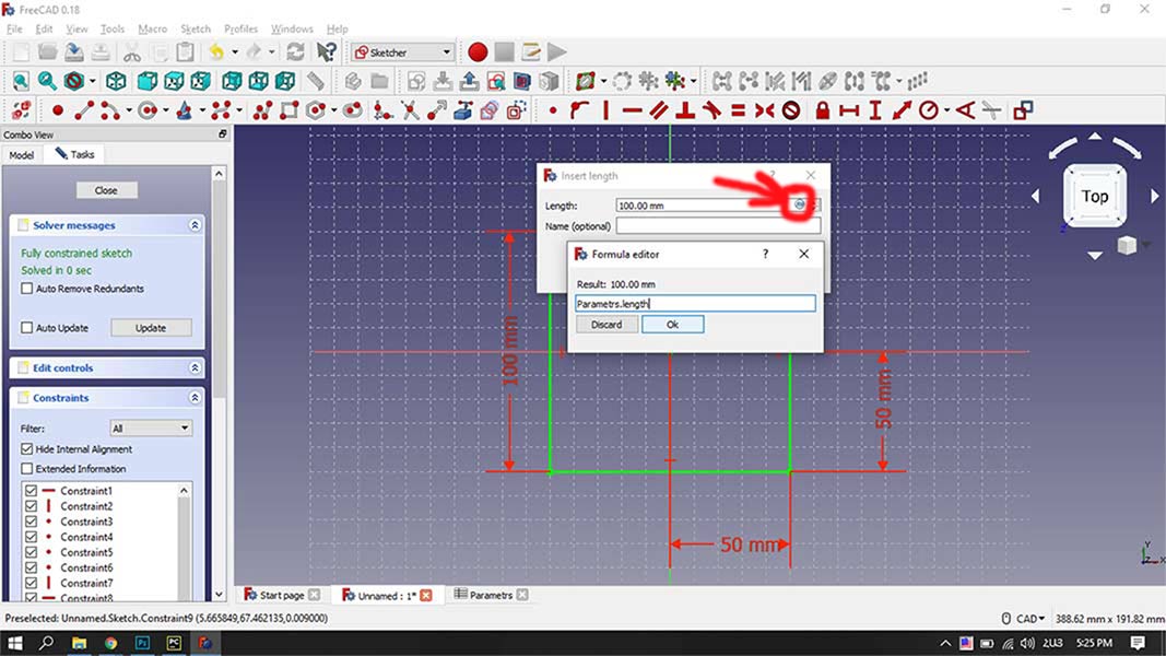
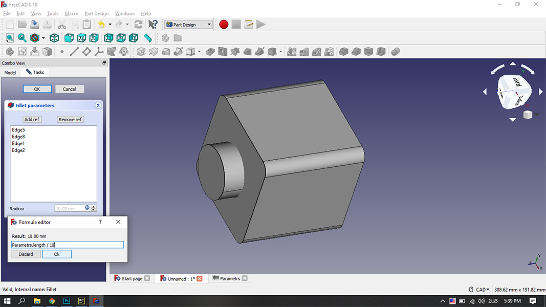
You can change parameters of the paddings, pockets and fillets by double clicking on then as shown below. In the Formula Editor tab you type some arithmetical formulas as well. In this case I wanted the Fillet diameter to be 1/10th of length of the side of the cube.
So all the parameters of the model are represented by the length. Now if I want to change the sizes of the model, I just have to go to the Parameters spreadsheet and change the value of length.
Downloadable file of this model Cube in FreeCad
Conclusion
For working with vectors both Illustrator and Inkscape are comfortable softwares, but Inkscape is open source, which is a huge advantage. Besides that, Inkscape has a much more beginner friendly interface. So I will continue using Inkscape. For 3D modeling I tried only FreeCad, and I really liked it. I will continue using it, as well as I will learn Fusion 360 in the near future. Parametric modeling is a very important thing, it makes life so much easier, when you work on a big project.