Final Project
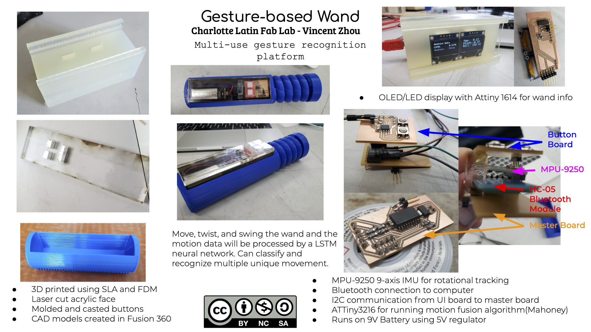
For my final project, I took insipiration from an idea that my teacher, Mr. Dubick, pitched. He pitched the idea of creating a wand that tracks movements and acts as a controller.
Slide and Video
Licensing
In week 14, I have decided to use the Creative Commons License-NonCommercial-ShareAlike license.
This work is licensed under CC BY-NC-SA 4.0. To view a copy of this license, visit https://creativecommons.org/licenses/by-nc-sa/4.0
Bill of Materials
| Component | # | Cost/Unit | Total |
|---|---|---|---|
| ATTiny412 | 1 | $0.46 | $0.46 |
| ATTiny1614 | 1 | $0.71 | $0.71 |
| ATTiny3216 | 1 | $1.00 | $1.00 |
| 1uF capacitor | 3 | $0.11 | $0.33 |
| 10k resistor | 4 | $0.10 | $0.40 |
| SSD1306 OLED | 2 | $4.80 | $9.60 |
| MPU-9250 | 1 | $8.99 | $8.99 |
| HC-05 | 1 | $9.49 | $9.49 |
| Single Sided FR-1 | 1 | $0.96 | $0.96 |
Total = $31.94
Bluetooth
The fab lab had quite a few assorted bluetooth modules labeled HM-10. I tried to configure the module with instuctions pertaining to the HM-10 bluetooth module. However, I released that my phone picked up a bluetooth module with the name HC-05. I searched up HC-05 and I found completely different instructions for setting up the HC-05. In order enter into AT mode, the key pin must be connected to 5V. In addition, the baudrate for the AT commands is 38400 but the baudrate for UART is 9600. The LED flashes slowly for UART and rapidly for AT mode.
UART Mode
AT Mode
After configuring the module in AT Mode, I attempted to connect to the module using the “nRF connect” app and send some serial data. However, the app kept throwing the GATT error.
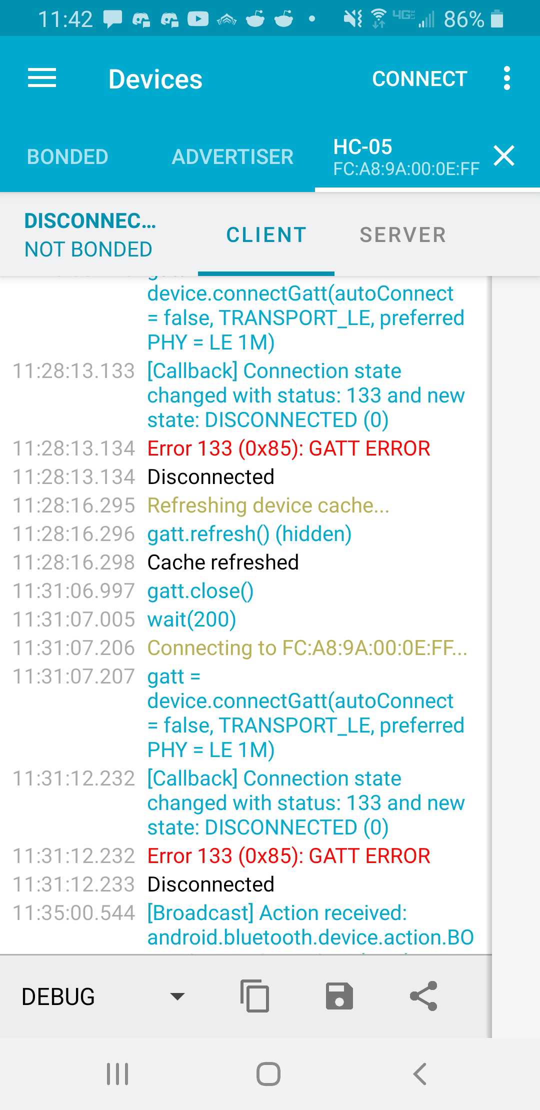
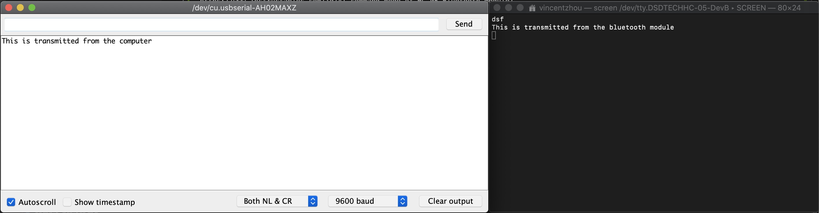
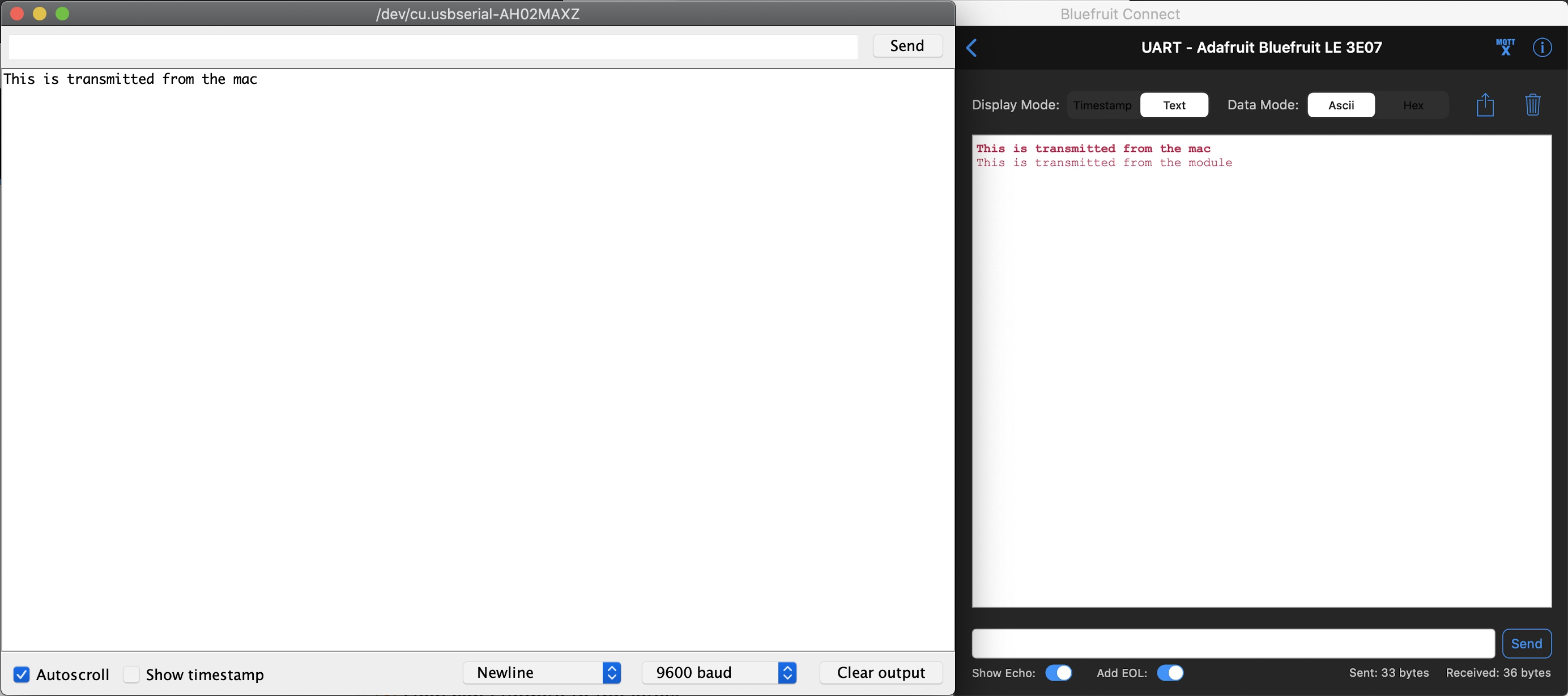
Multiple searches reavealed that the error was due Android’s incompatibility with certain bluetooth devices. So, I used my MacBook to perform serial communication with the module using this guide. I could successfully transmit serial data wirelessly!
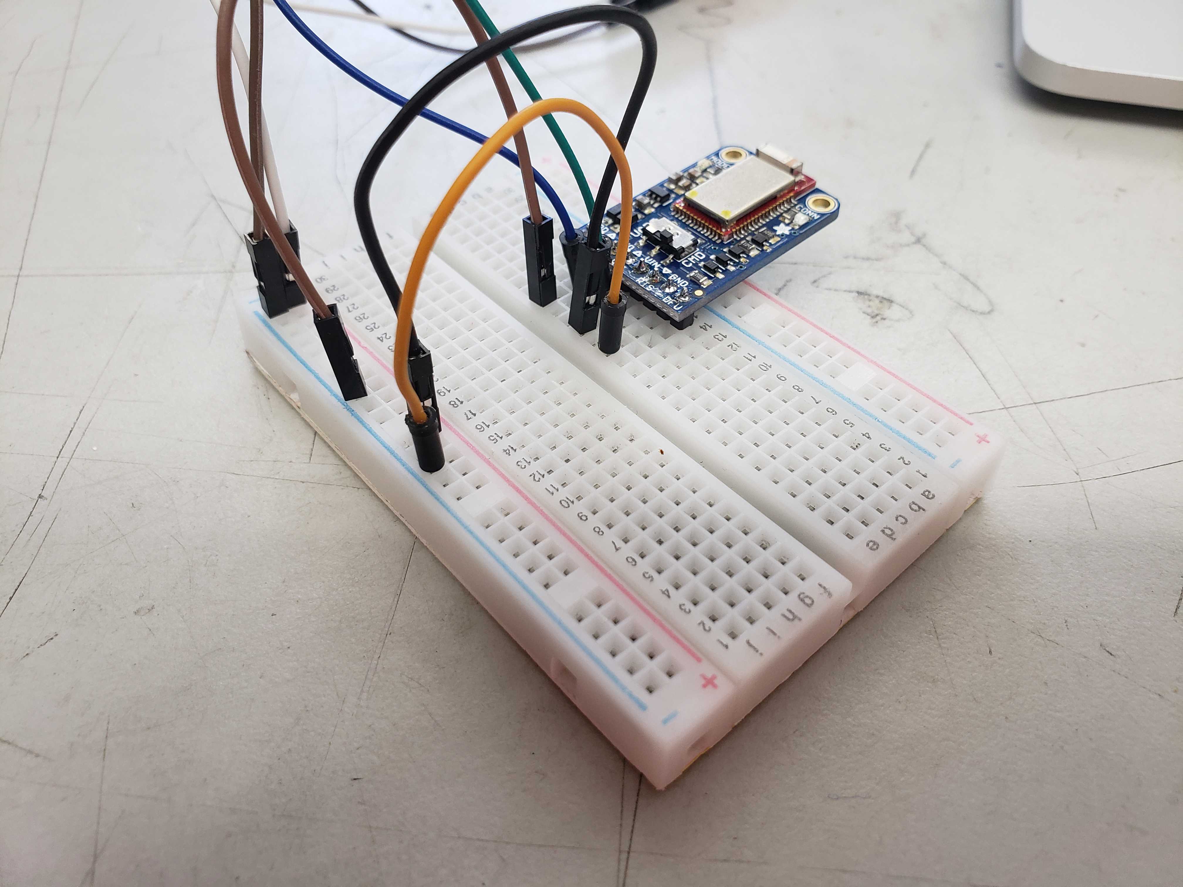
I also successfully used the Adafruit Bluefruit LE UART Friend to transmit serial data. I referenced the instruction guide for the operation of the module. The Adafruit module operates in almost the same way except that switching to AT mode is done by toggle a physical switch and that the CTS pin must be connected to GND. In addition, the module doesn’t show up in my Macbook’s bluetooth menu and can only connect via the Adafruit Bluefruit application. This caveat made me decide to the use the HC-05 as my bluetooth module.
MPU-6050 IMU
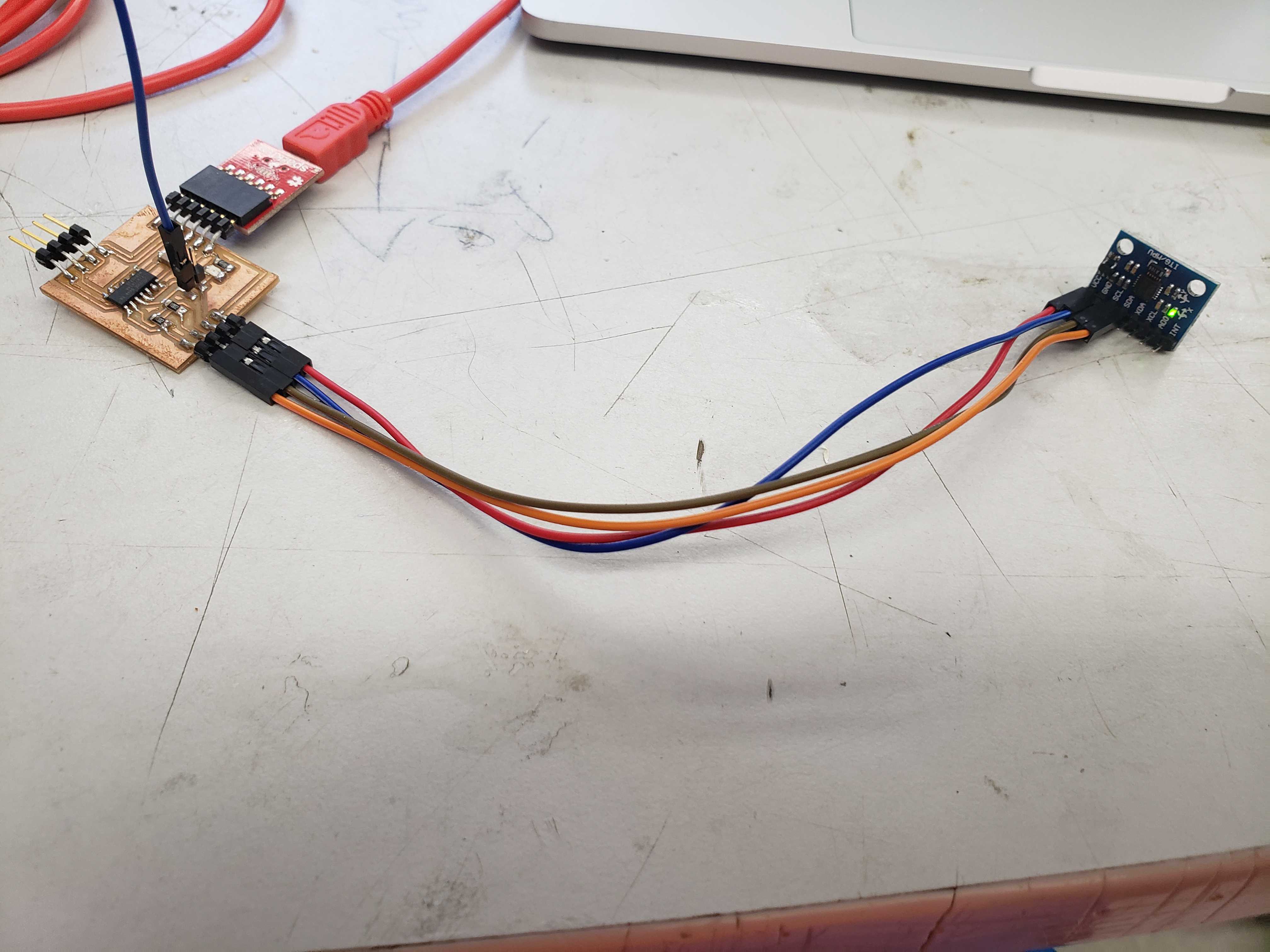
Since the fab lab had MPU-6050s readily available, I decided to use a MPU-6050 for motion tracking and I found a tutorial detailing how to extract gyro and accelerometer values through I2C and calculate rotation. I reused my master board from the Networking and Communications week as it was designed for I2C in mind.
However, I realized that yaw calculations were missing from the IMU code. After more researching, I came across a thread that provided the exact calculations. Furthermore, I also researched the meaning of the raw values from the sensors and came across a thread asking the same questions. The gyroscope is a rate gyro that outputs change in degrees per second. The accelerometer outputs the acceleration in Gs.
double x = Ax;
double y = Ay;
double z = Az;
pitch = atan(x/sqrt((y*y) + (z*z))); //pitch calculation
roll = atan(y/sqrt((x*x) + (z*z))); //roll calculation
yaw = atan (z/sqrt((x*x) + (z*z)));
pitch = pitch * (180.0/3.14);
roll = roll * (180.0/3.14);
yaw = yaw * (180.0/3.14);
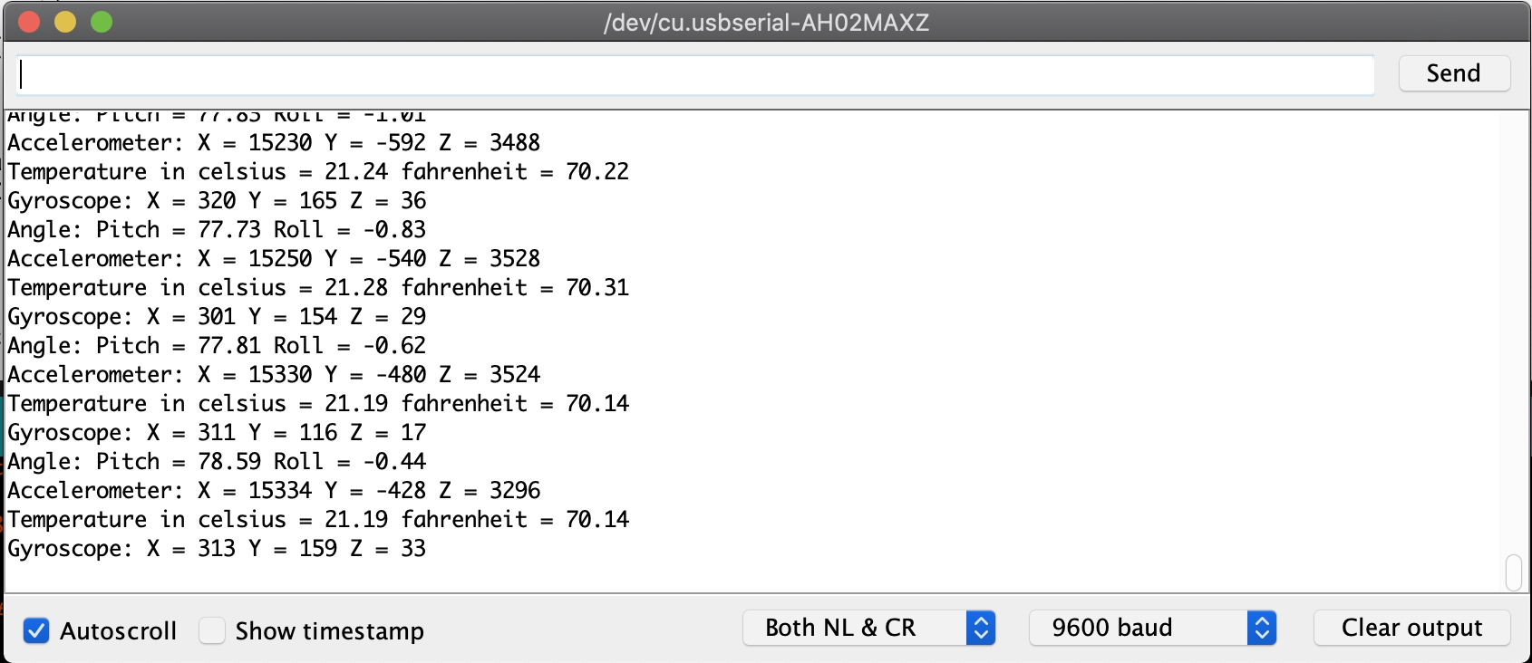
The code was able to output data to serial. However, I couldn’t discern the quality of the rotational from purely number alone. In order to view the rotational data, I created a Processing program that would rotate a sphere by the information given by the IMU. The program revealed that the output was actually unstable and jittery.
Fortunately, during the input week, Sophia Vona found better code from this site that outputs more stable and fluid readings with the help of a complementary filter. Reading the comments of the code closer revealed that the code came with a built in drift correction. While the IMU is still, the function takes multiple samples from both sensors and averages the samples to produce a bias. I invoked the function to print out the bias values and adjusted the biases accordingly.
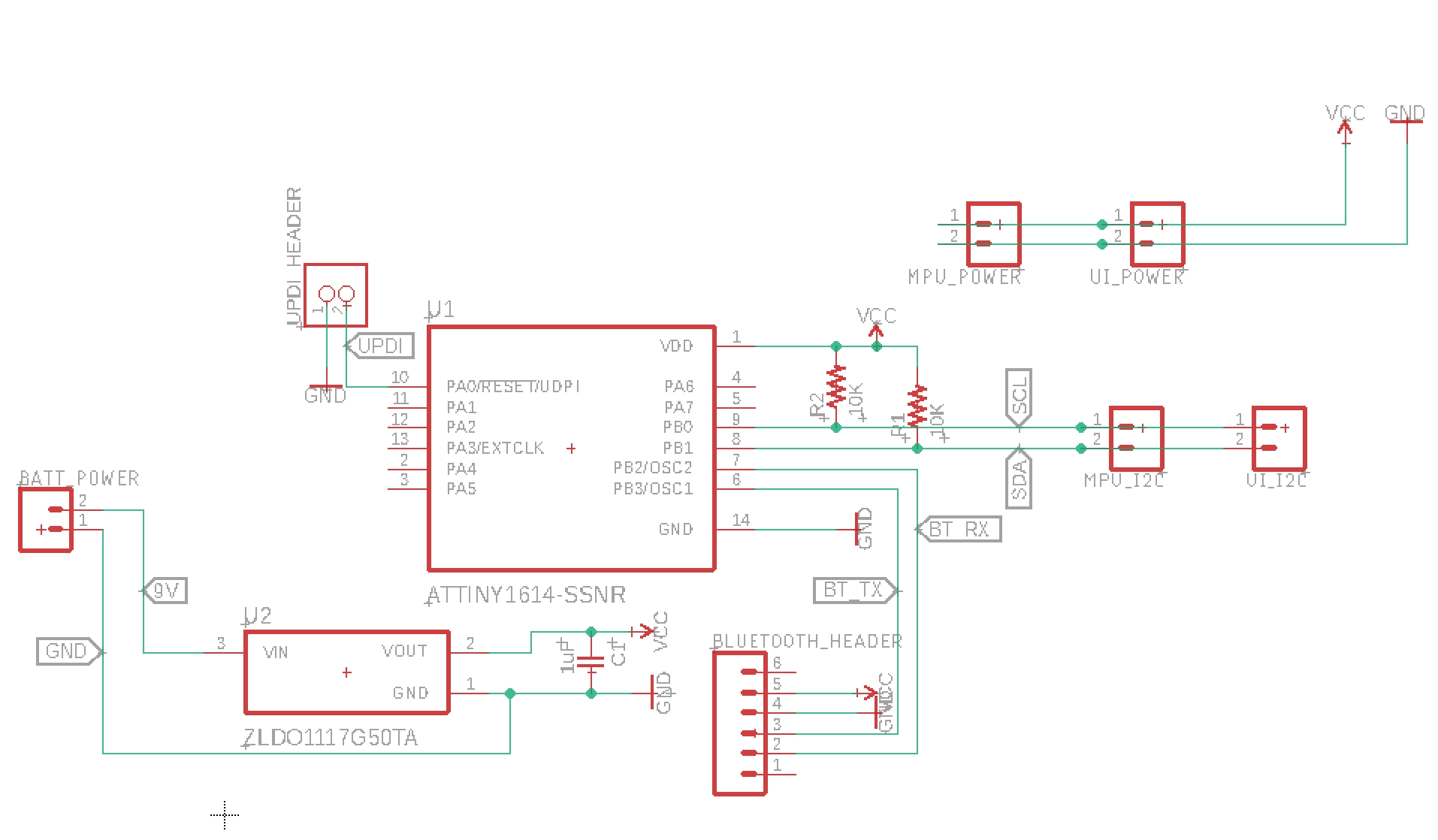
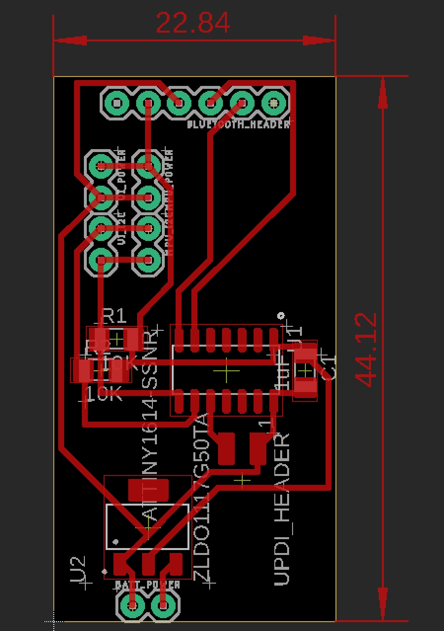
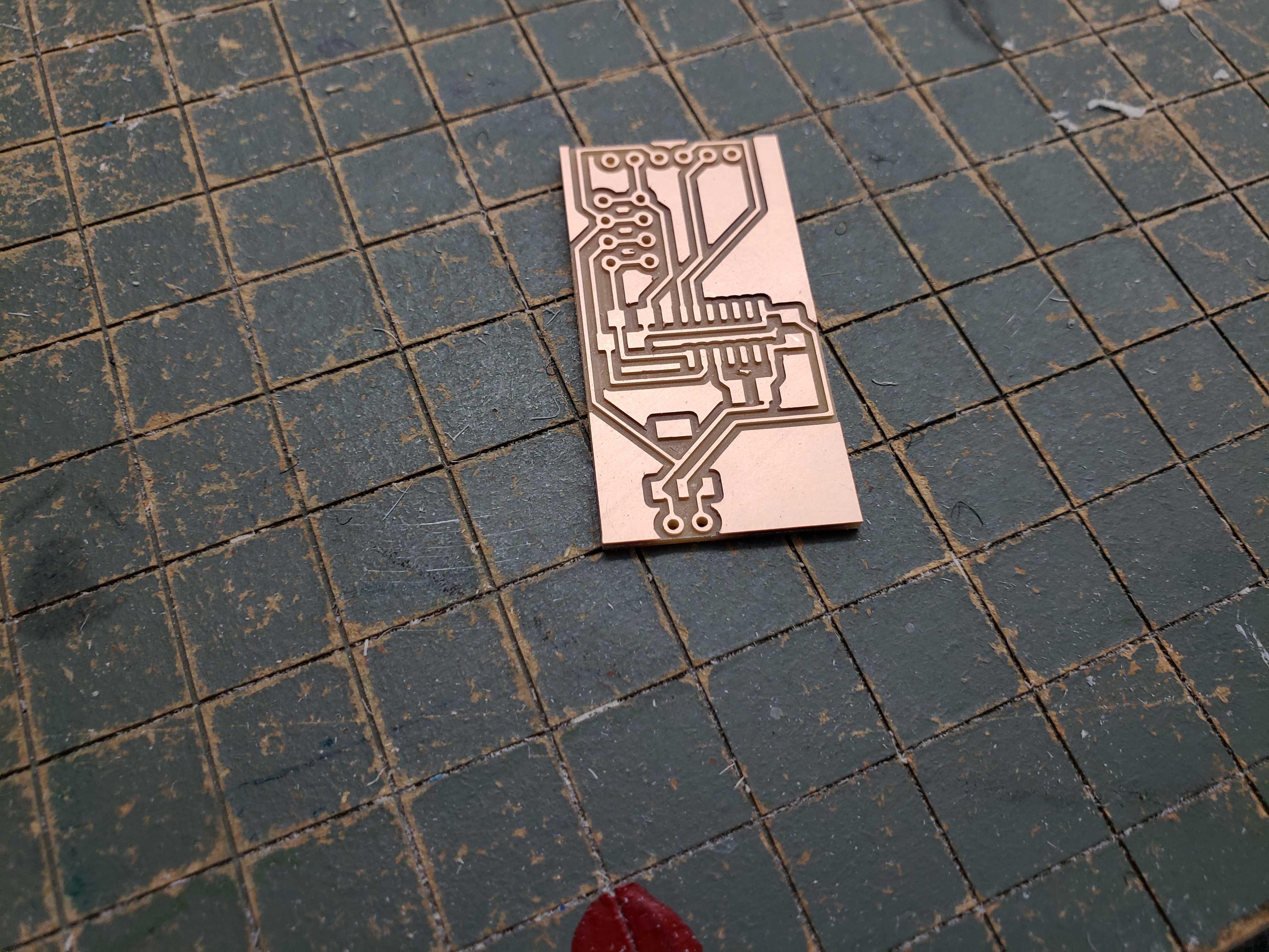
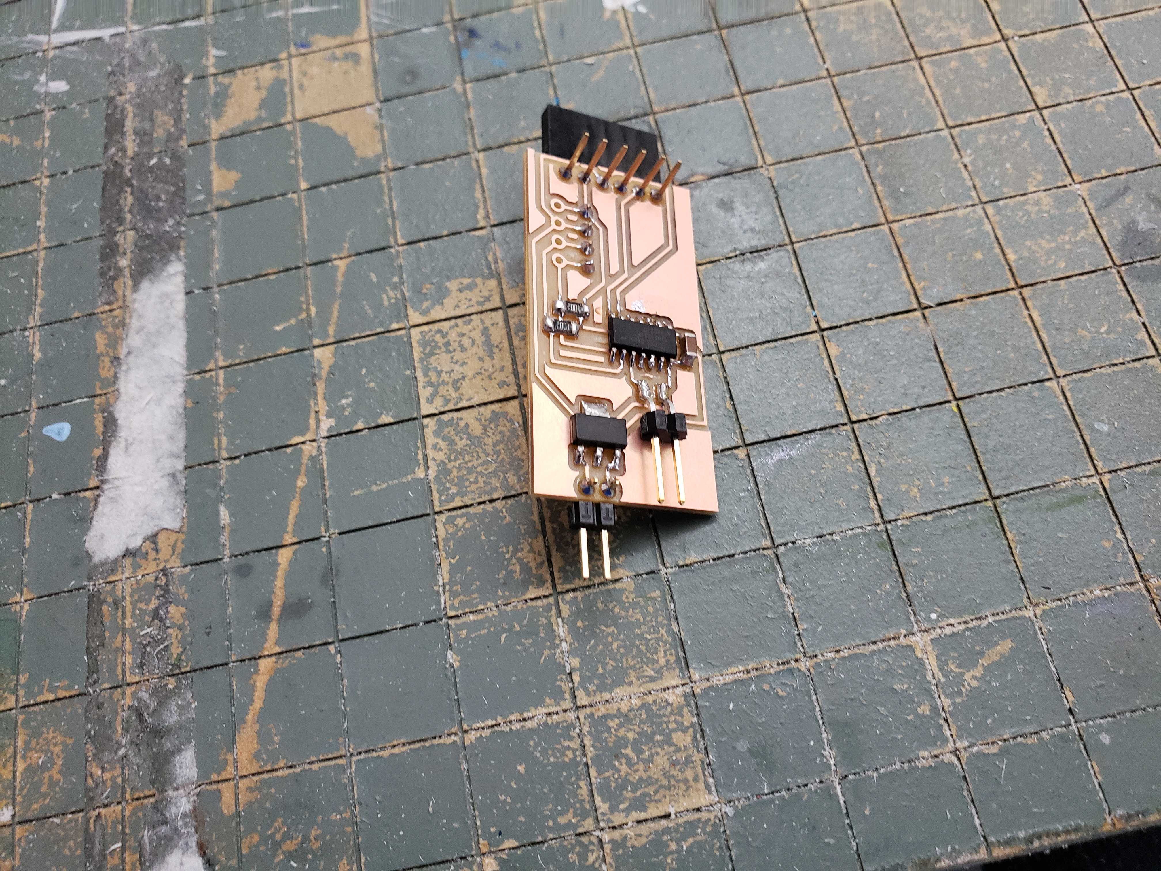
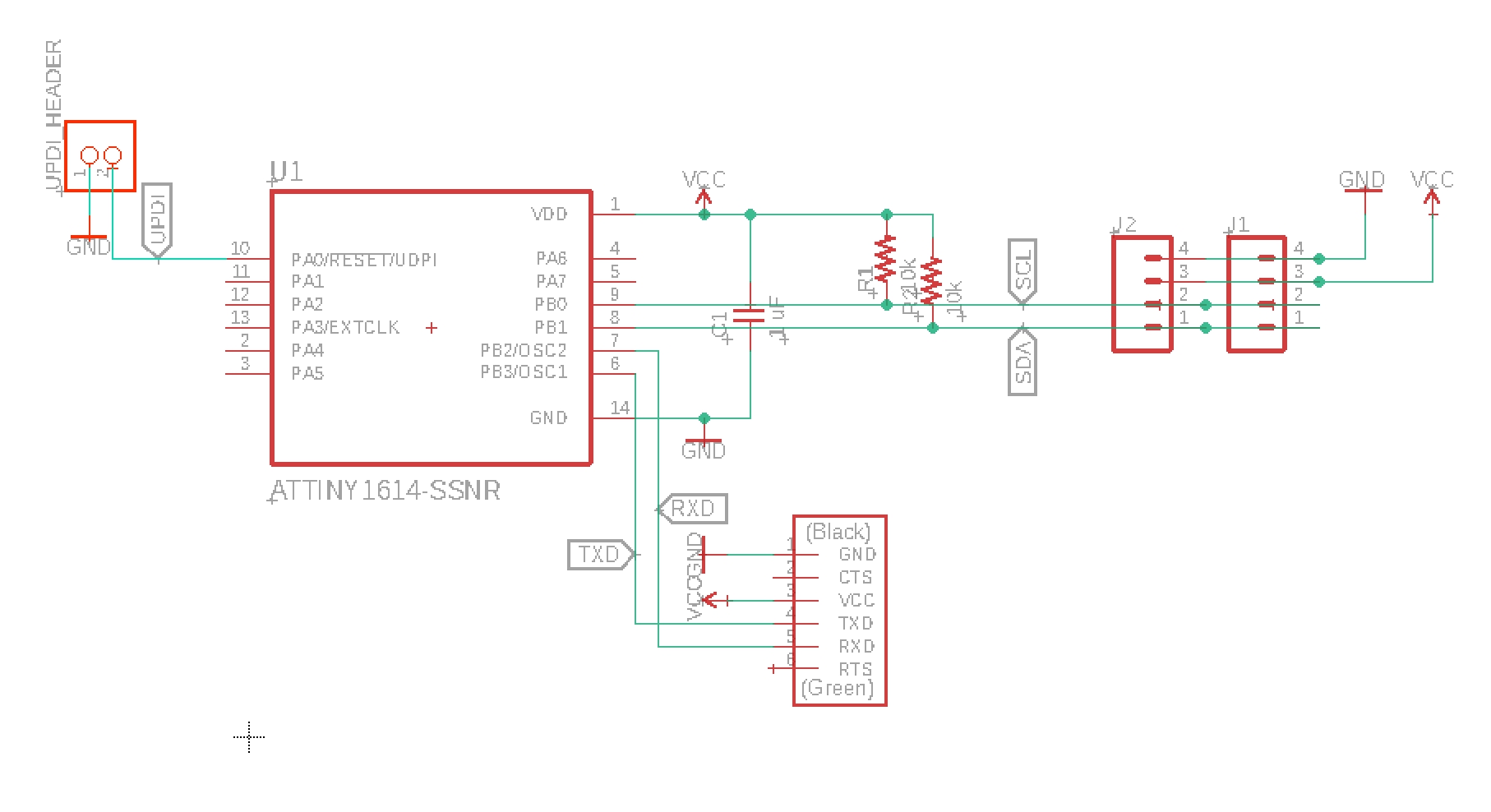
ATTiny1614 Boards
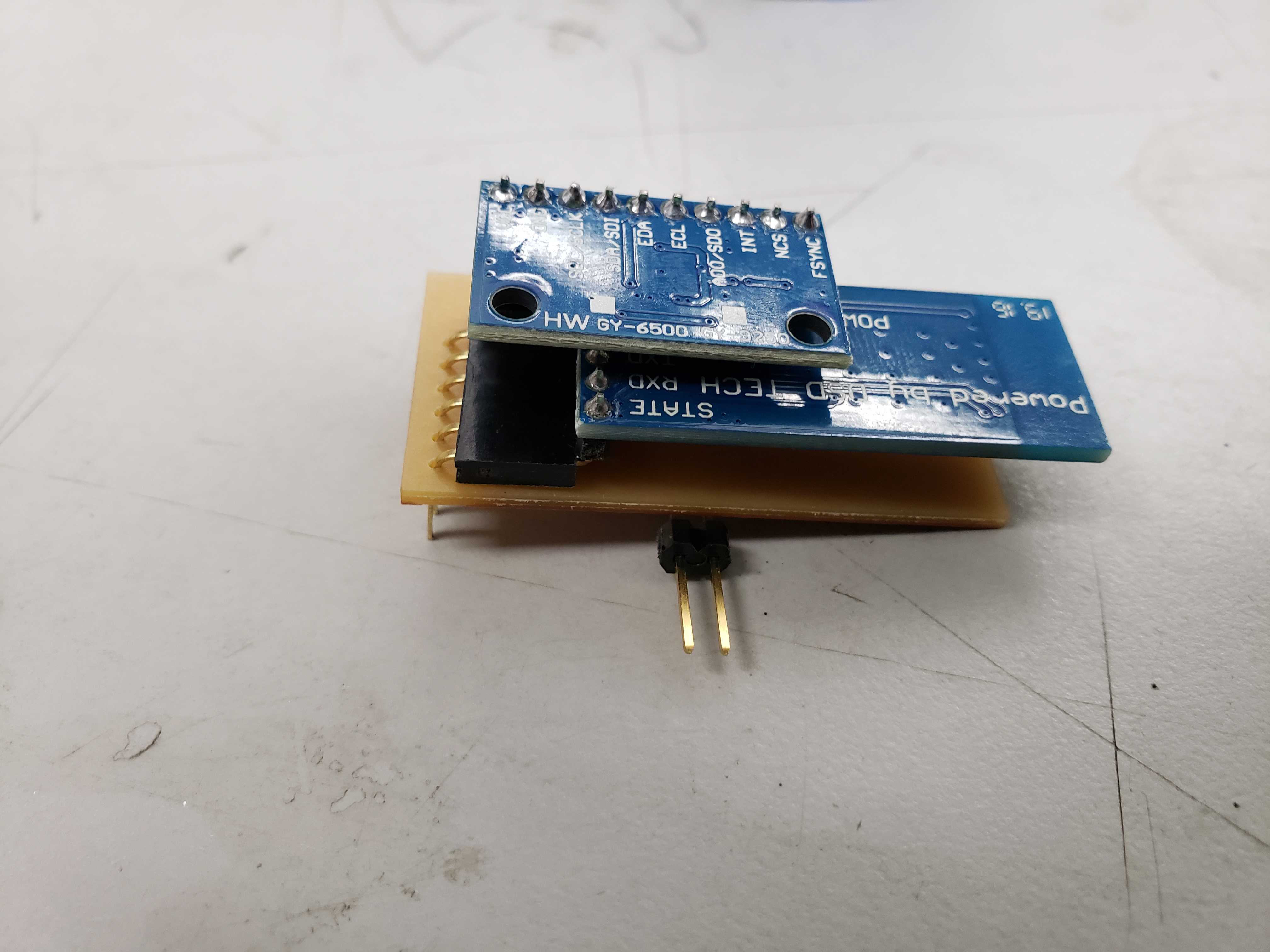
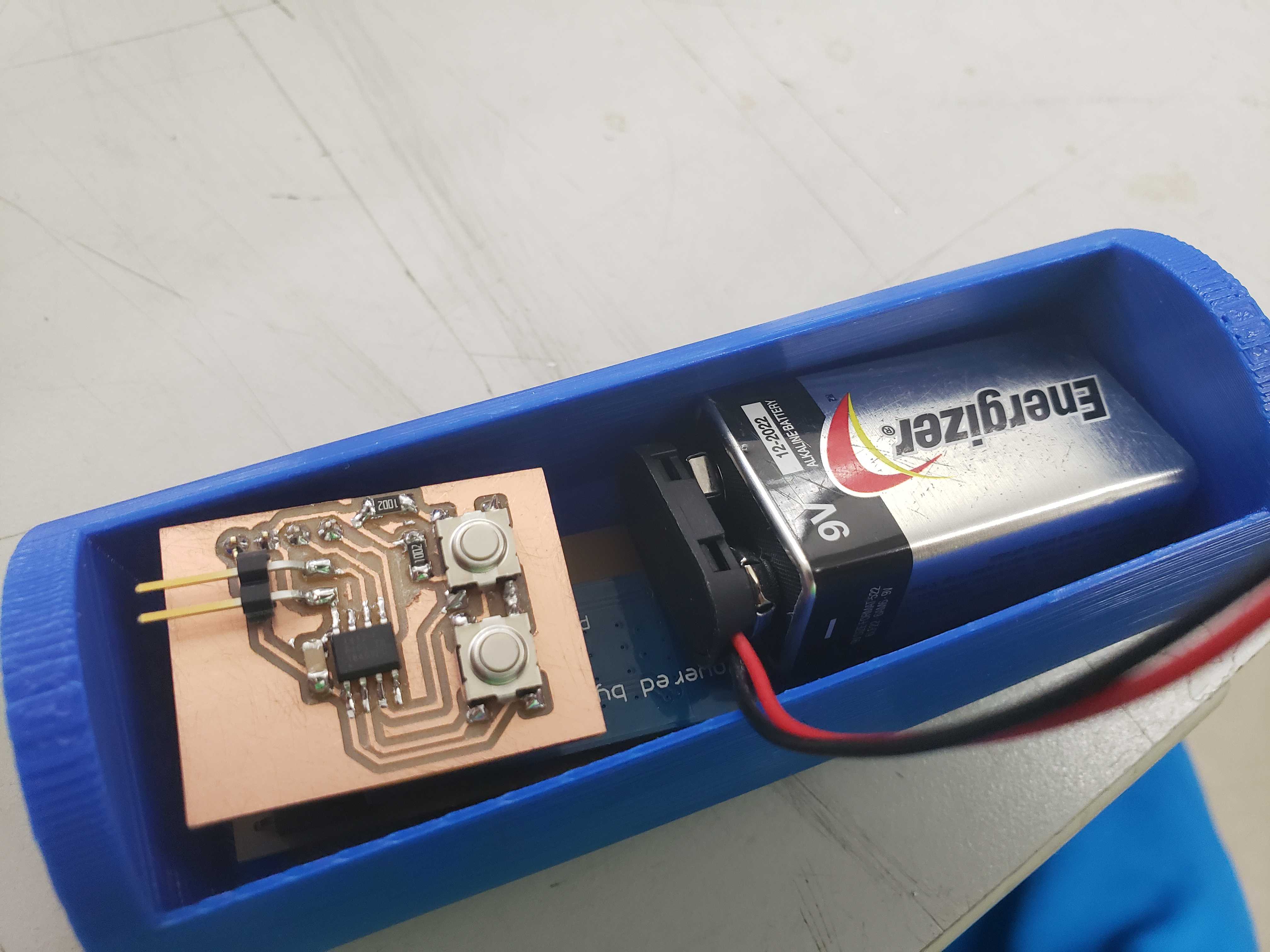
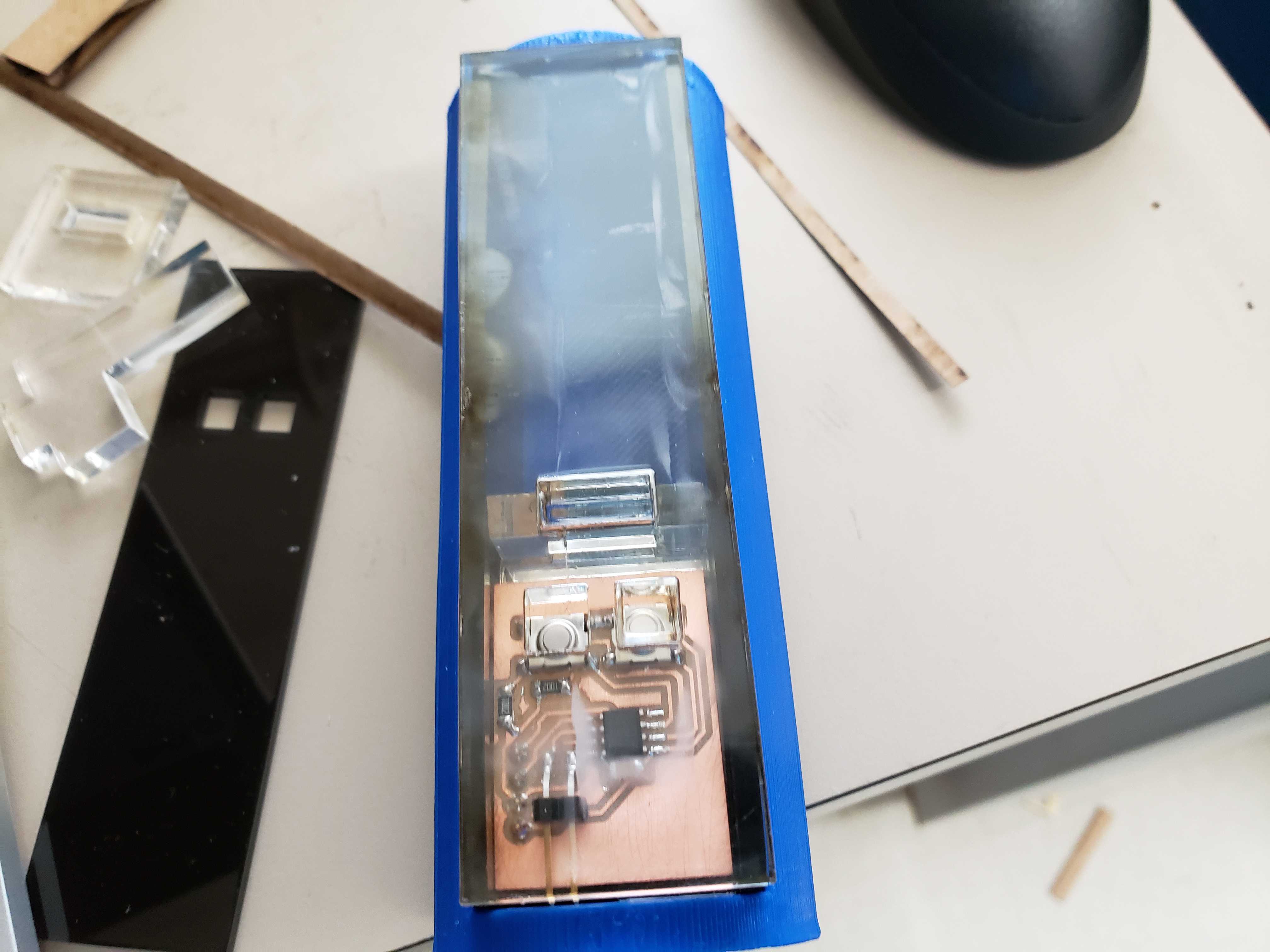
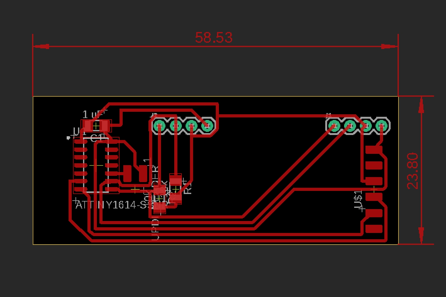
With a solid foundation in rotation measurement, I designed and milled out a board to allow the HC-05 to directly plug into a female header on the board. In addition, I added two more 4-pin female headers to allow for the IMU to dirctly plug in as well as an auxilary board. On the back of the board, I added a 5v regulator so that I could attach a 9v battery for portable power.
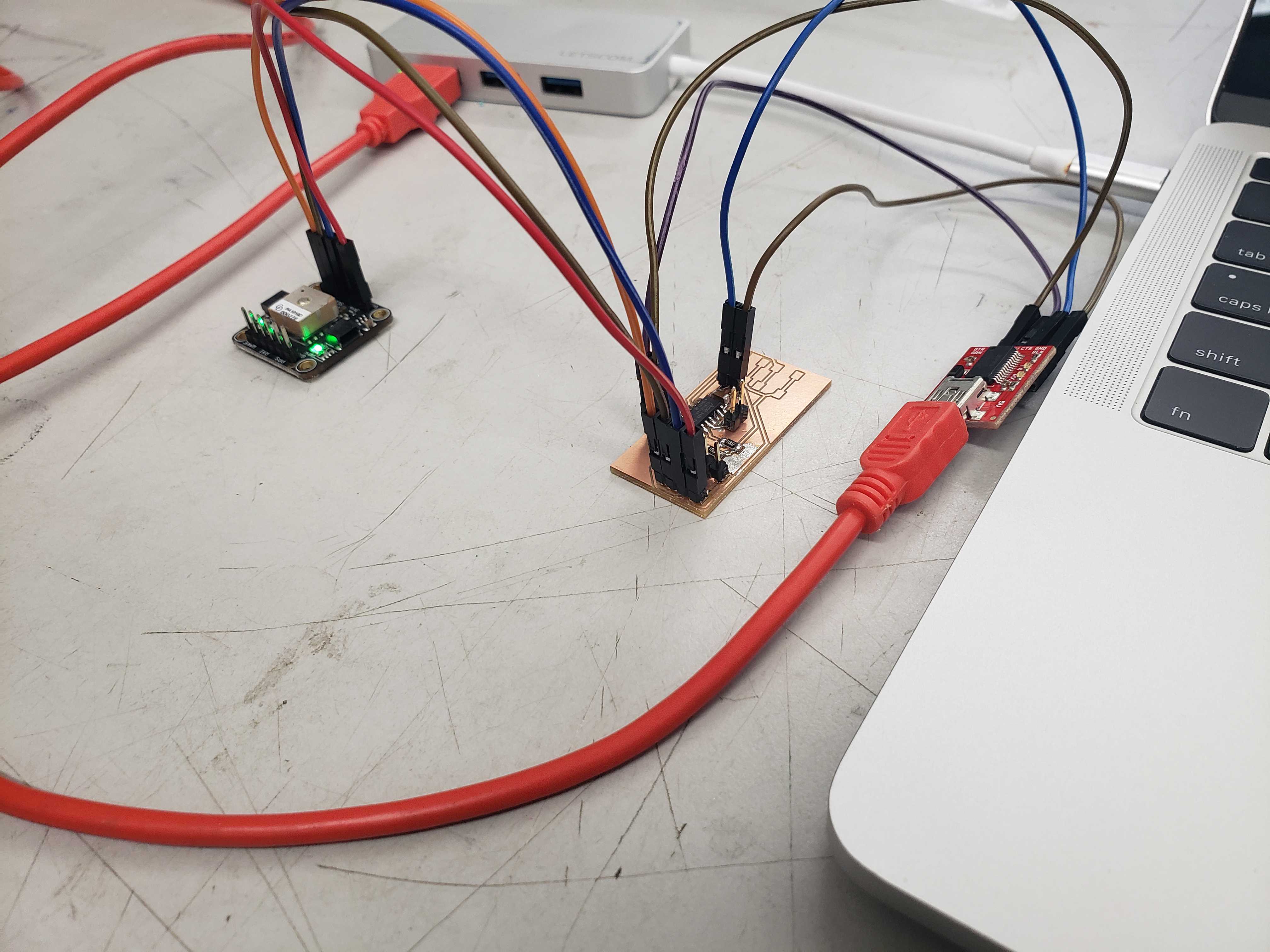
GPS Attempt
I decided to take the wand a step fruther and implement absolute potisioning. Positioning was the most difficult part because the accelerometer is fixed body sensor, meaning that gravity would be included in the acceleration readings. In addition, accelerometers are notoriously inaccurate when in comes to positioning due to dead reckoning and the accumulation of error from double integration. I decided that I could fuse data from a GPS to the IMU to create a stable measurement of rotation and position. I found that the lab had a compact GPS receiver that could communicate to a MCU via I2C or SPI. I used a spare I2C capable board that my brother, a fab academy student, had fabricated for a previous week.
However, the Adafruit GPS library was too large for the 16kb of memory on the ATTiny1614.
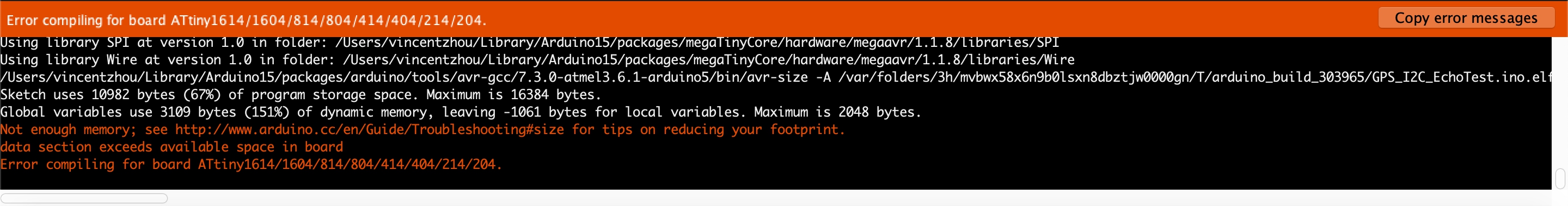
Instead, I had to parse and query the information on my own. To start, I requested an abritrary number of bytes and printed the results to serial.
#include <Wire.h>

void setup() {
  // put your setup code here, to run once:
  Wire.begin();
  Serial.begin(9600);
}

void loop() {
  // put your main code here, to run repeatedly:
  Wire.requestFrom((byte)0x10, 64, true);
  for (int i = 0; i < 32; i++) {
    char c = (char) Wire.read();
    if (c != 0x0A) Serial.print(c);
  }
  Serial.println();
  delay(100);
}
All GPS systems output data in the NMEA format, so I took a look at the sytax of the NMEA sentences in order to break down the sentences in useful pieces of information.
Ultimately, the GPS provided infeasible because the module couldn’t obtain a fix after 30 minutes. The compact nature of the antenna meant that the GPS module could not get a fix if anything obscured the sky. However, during my research in fusing GPD and IMU data, many threads and forums recommended using a magnometer to obtain true orientation in relation to the Earth and increase the performance of fusion algorithims. As a result, I switched to the MPU-9250 which is MPU-6050 with an AK8963 magnometer. I came across the articles and the github of Kris Winer who experimented heavily with the MPU-9250 and provided alot of code to get started.
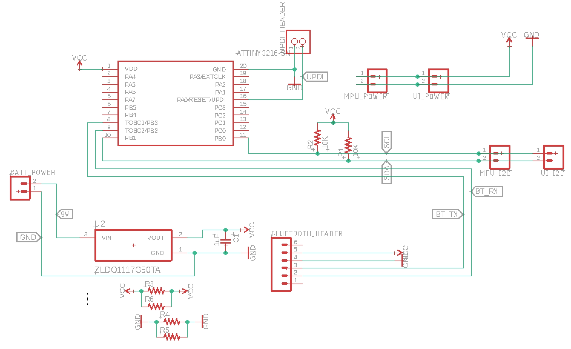
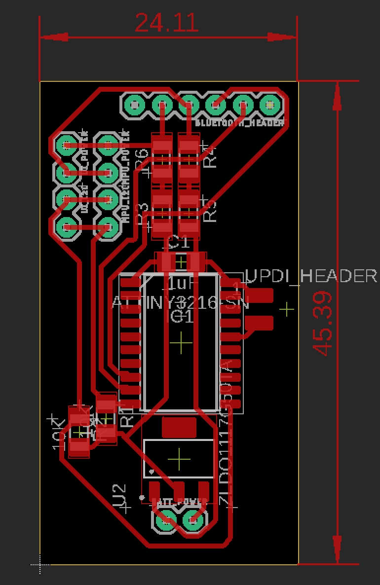
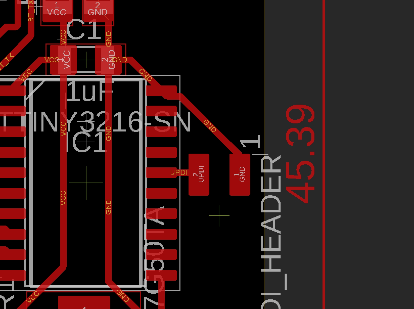
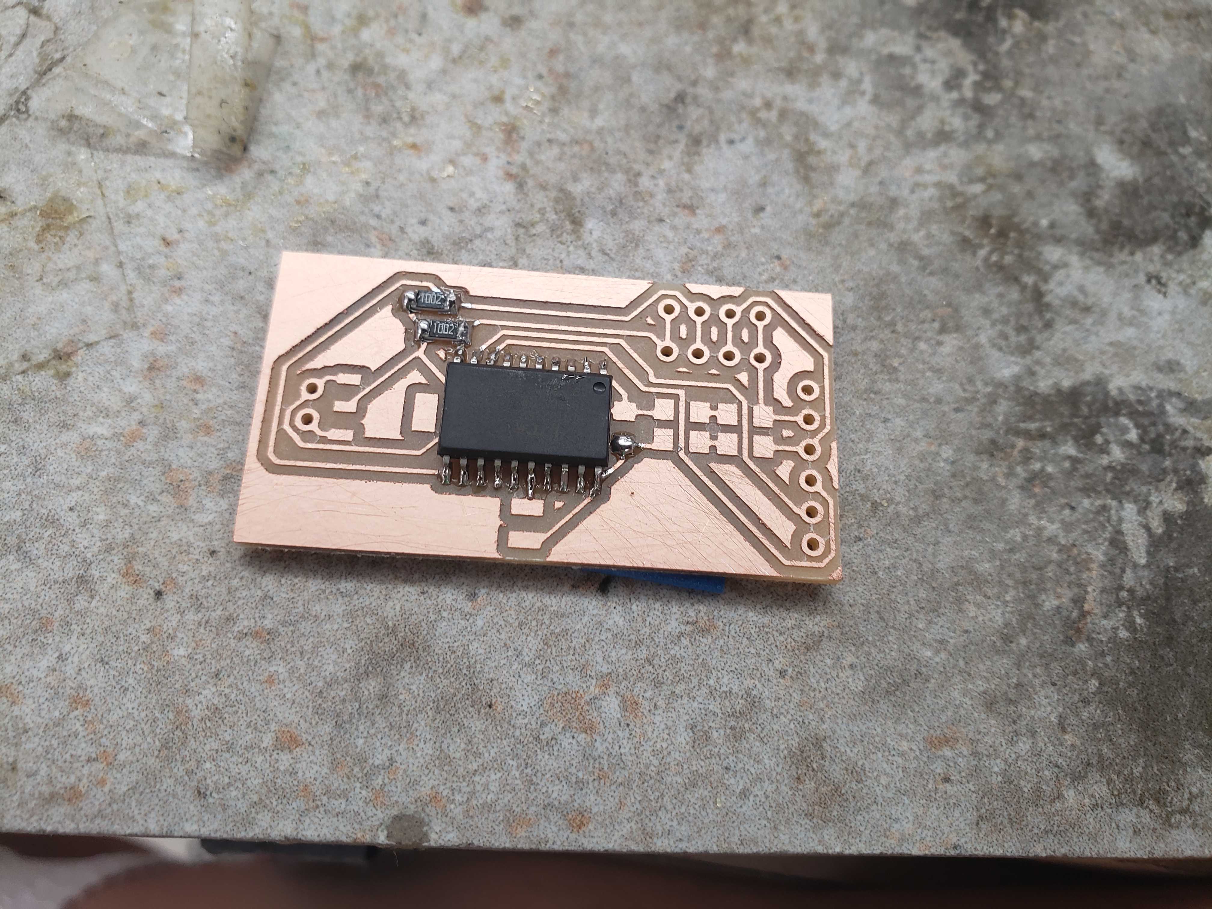
ATMega328p and ATTiny3216 boards
Unfortunately, the code that Kris Winer uses is larger than the 16kb limit of the ATTiny1614. As a result, I designed two types of boards: one with the ATMega328p chip and one with the ATTiny3216 chip. The reason for the dual design is that the ATTiny3216 is easier to use but the lab didn’t carry the chip due to the cost. I acquired only 3 ATTiny3216s from Mr.Rudolph, a fablab helper. This left little room for prototyping and error.
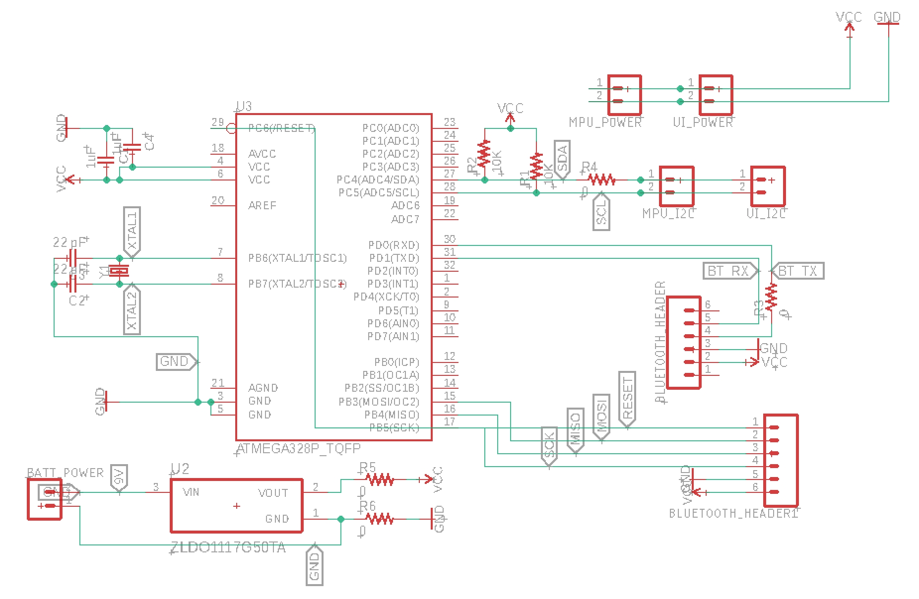
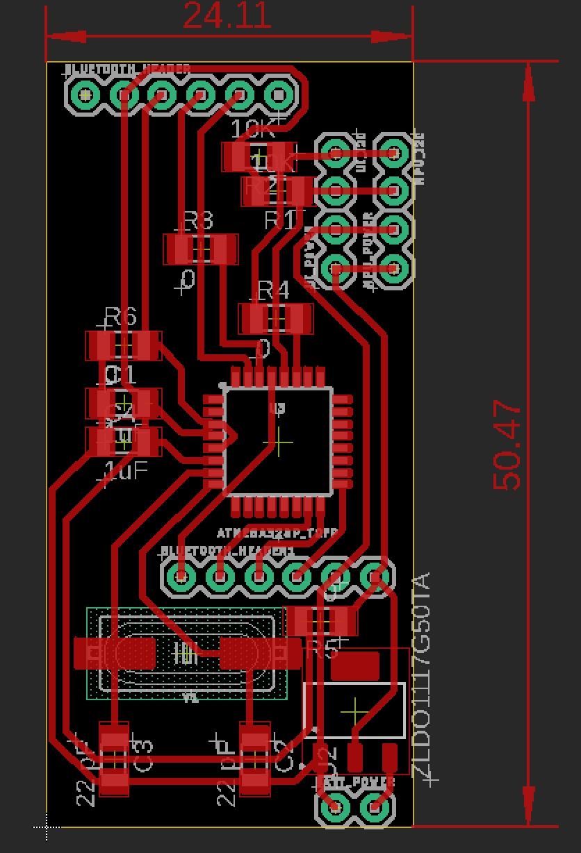
Meanwhile, the lab had plenty of ATMEga328p chips. However, the older chip uses the larger ICP header for programming and is more difficult to design and solder. In order to run the chip at 16 mHz, the chip needs to be connected to a 16 mHz crystal resonator with two 22 pF capacitors as well as several bypass capacitors.
The larger chips also raised the issue of component placement. I had to shuffle many components, including the 2 4-pin I2C headers, around in order to make the autorouter work or to make manual routing easier.
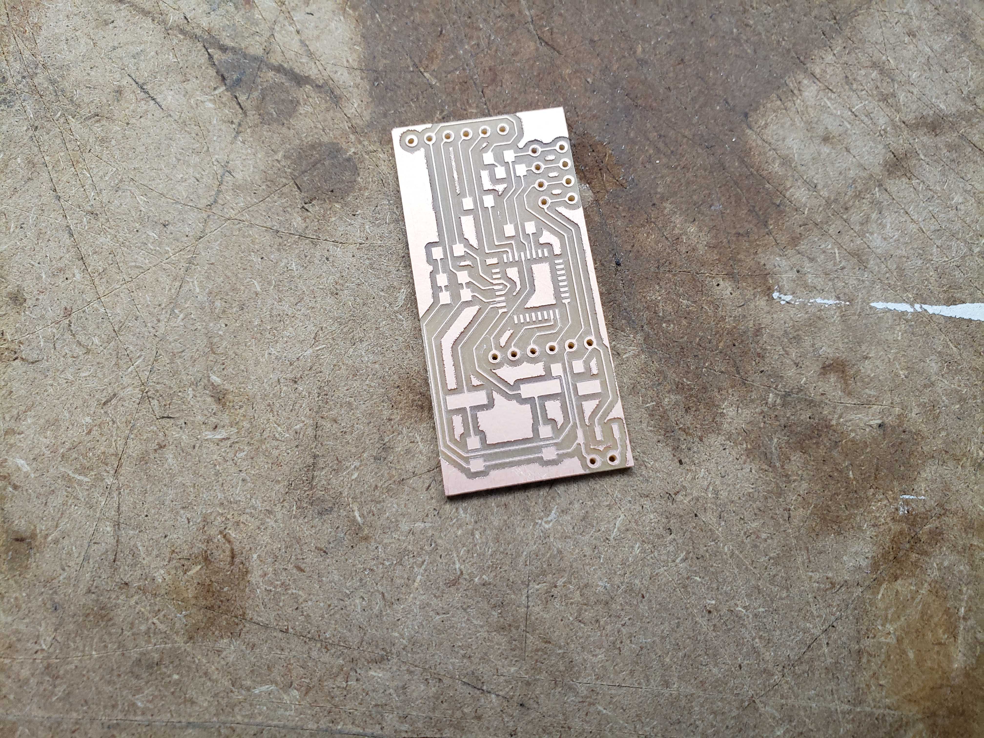
ATMega328p
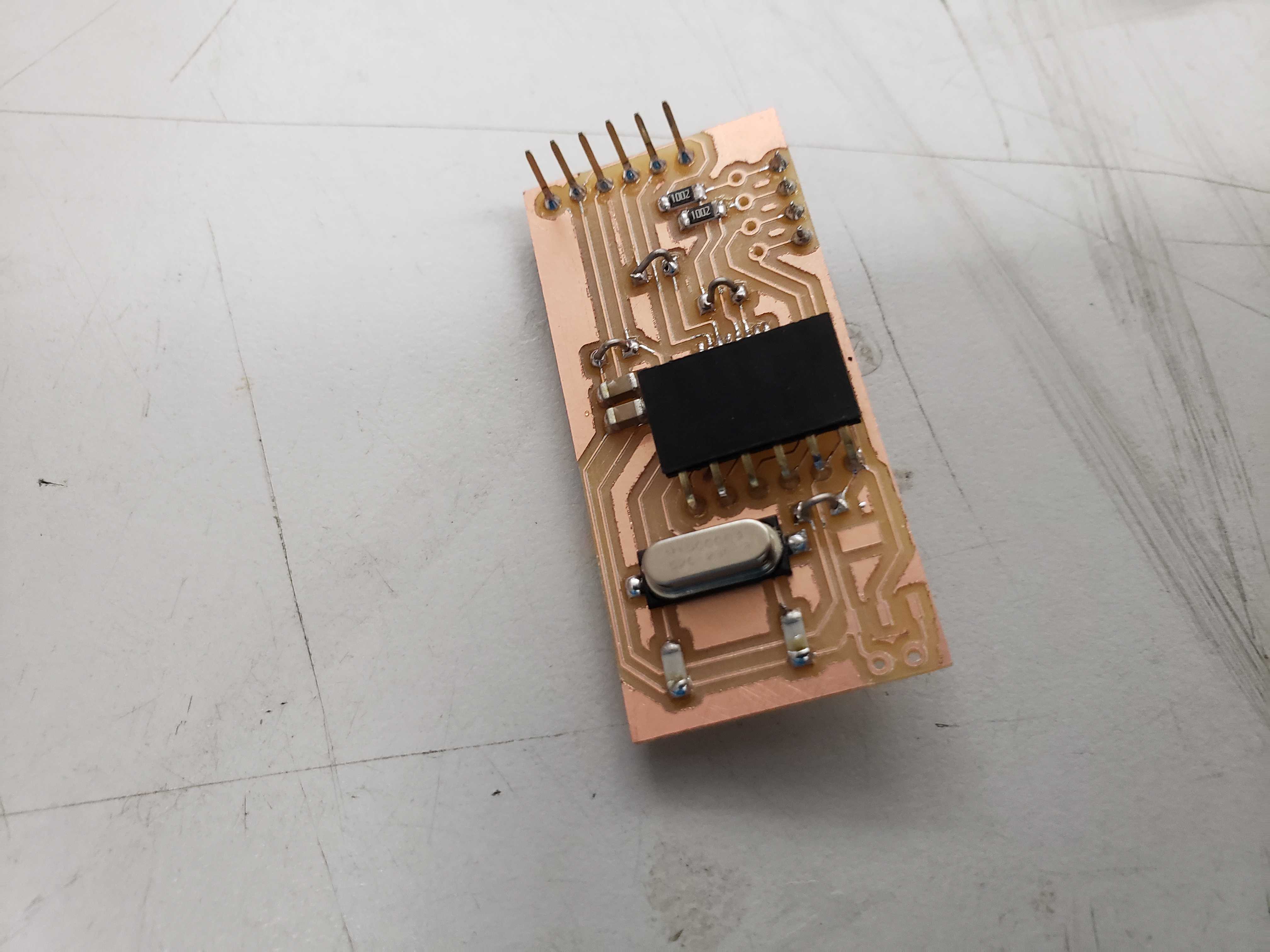
ATTiny3216
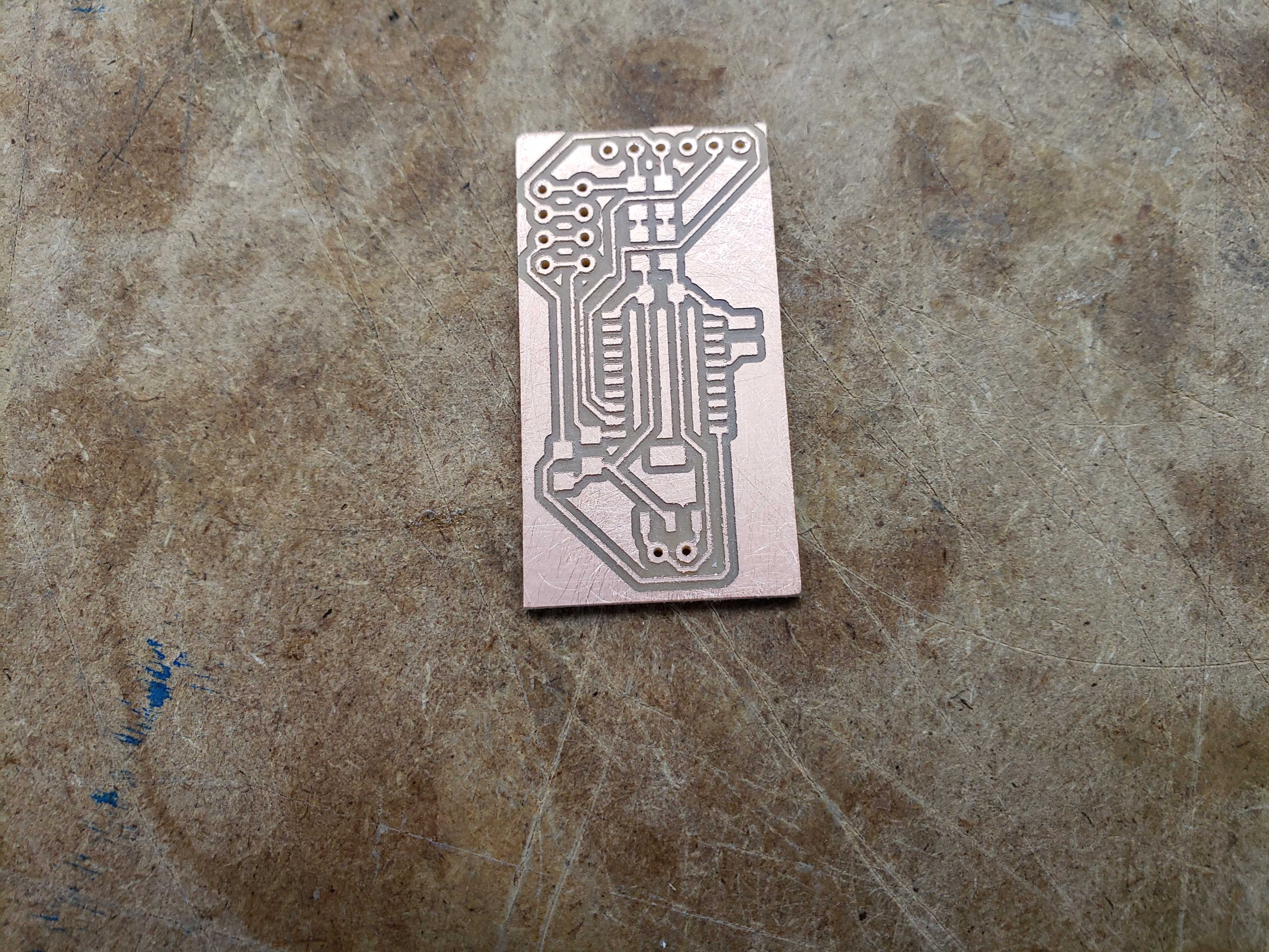
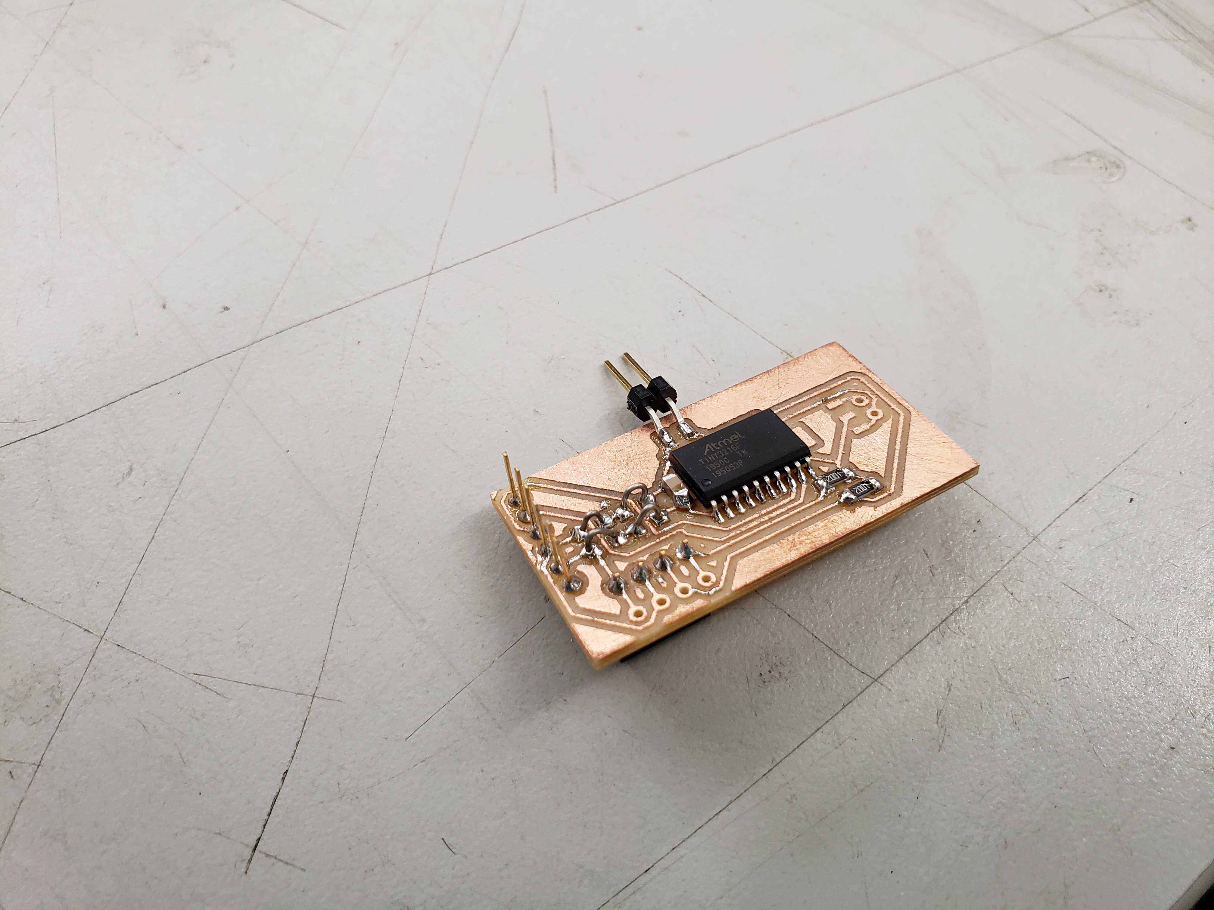
I remilled and soldered another ATTiny3216 board because I realized that the UPDI headers was jutting out from the side. However, all programming and testing was done with the erroneous board to preserve the limited supply of ATTiny3216s. The correct ATTiny3216 board was used in the final project.
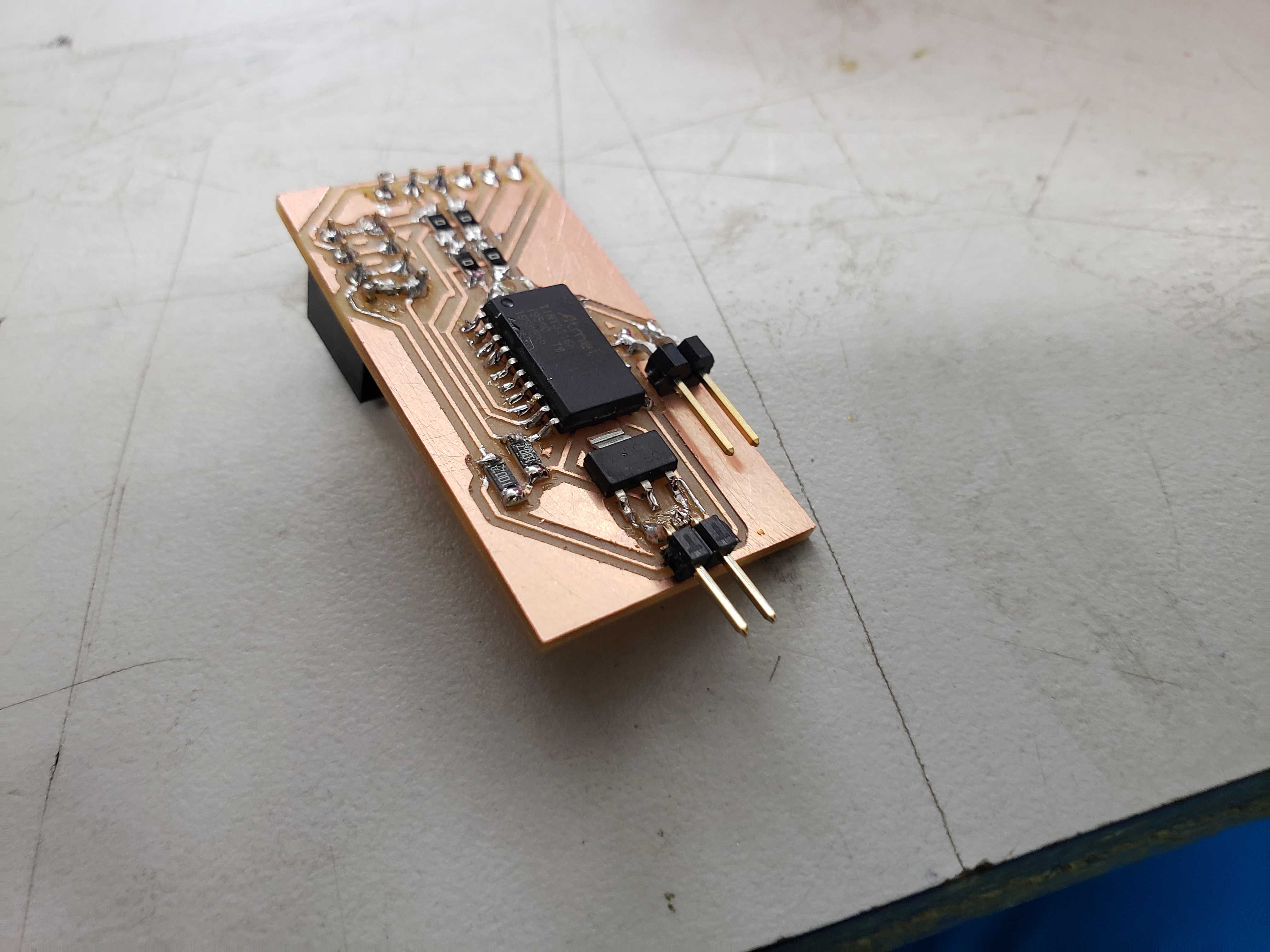
In the end, the ATMega328p board failed to program as the chip would return a chip signature of 0x00. Meanswhile. the ATTiny3216 board functioned as expected with the IMU and the HC-05 module fiting nicely together. As a result, I retired the ATMega328p boards in favor of using the ATTIny3216 boards in my final project.
MPU-9250 IMU
Kris Winer’s code was originally designed for the Arduino Uno with an LED screen. I stripped out all of the lines that pertained to the LED screen. Furthermore, the code seemed to be incomplete as the code references a Mahony motion fusion functions. I found that the function was defined in a seperate file and I merged the function declaration into the main sketch. Unfortunately, the code produced seemingly random rotations on axes that I didn’t even turn.
On the the github issue tracker, the main culprit seems to be incorrect magnometer calibration.
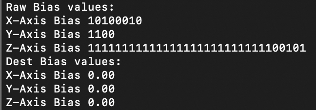
I read Kris Winer’s article about implementing additional calibration to the magnometer of the MPU9250. This article showed the implementation of the Kris Winer’s calibration code within his AHRS code. However, despite the added calibration, the weird iteraction between the axes continued. Curiously, I decided to print the values of the calculated magnometer bias and the magnometer scale. While the magnometer scale looked fine, the bias was zero! I tried different implementations of the function and thought that the bias might actually be zero. However, I was finally convinced that zero bias was impossible and decided to print intermediary values to see what values actually correlated to zero bias.
Serial.println("Raw Bias calculation values: ");
Serial.print("X-Axis Value "); Serial.println((mag_max[0] + mag_min[0])/2);
Serial.print("Y-Axis Value "); Serial.println((mag_max[1] + mag_min[1])/2);
Serial.print("Z-Axis Value "); Serial.println((mag_max[2] + mag_min[2])/2);

// Get hard iron correction
mag_bias[0]  = (mag_max[0] + mag_min[0])/2;  // get average x mag bias in counts
mag_bias[1]  = (mag_max[1] + mag_min[1])/2;  // get average y mag bias in counts
mag_bias[2]  = (mag_max[2] + mag_min[2])/2;  // get average z mag bias in counts

Serial.println("Raw Bias values: ");
Serial.print("X-Axis Bias "); Serial.println(mag_bias[0]);
Serial.print("Y-Axis Bias "); Serial.println(mag_bias[1]);
Serial.print("Z-Axis Bias "); Serial.println(mag_bias[2]);

dest1[0] = (float) mag_bias[0]*mRes*magCalibration[0];  // save mag biases in G for main program
dest1[1] = (float) mag_bias[1]*mRes*magCalibration[1];
dest1[2] = (float) mag_bias[2]*mRes*magCalibration[2];

Serial.println("Raw Bias final values: ");
Serial.print("mRes "); Serial.println(mRes);
Serial.print("X-Axis Bias "); Serial.println(mag_bias[0]*mRes*magCalibration[0]);
Serial.print("Y-Axis Bias "); Serial.println(mag_bias[1]*mRes*magCalibration[1]);
Serial.print("Z-Axis Bias "); Serial.println(mag_bias[2]*mRes*magCalibration[2]);
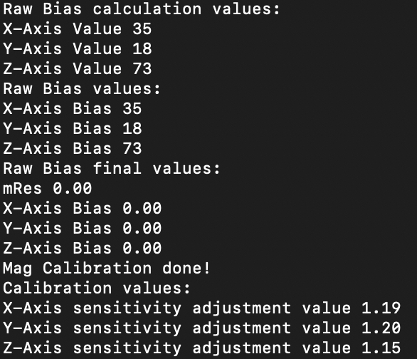
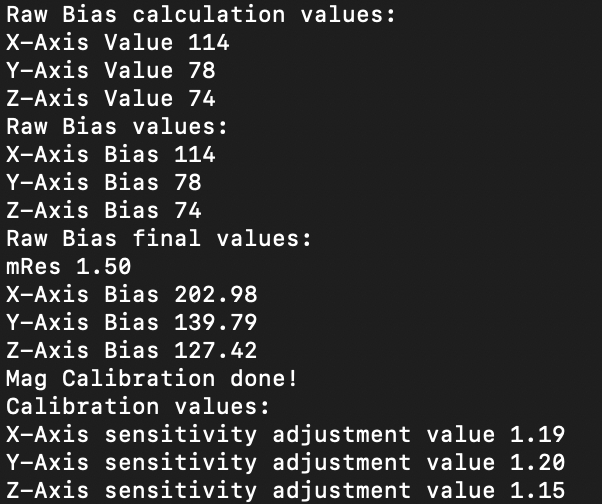
The raw bias values clearly showed that there were non-zero bias values that became zero after scaling by resolution and calibration. Printing out the mRes revealed that mRes was causing the assignment of magBias to remain zero! The question became why the mRes was zero because I knew that the getMres() function populated the mRes variable. It turns out the getMres() function is only called in the main loop, while the magcalMPU9250() function is called in the setup function. mRes had not been initialized! I placed the getMres() function before the bias calculations to fix the issue.
getMres(); //Mres would be zero without this line. This was the problem the ENTIRE time.

dest1[0] = (float) mag_bias[0]*mRes*magCalibration[0];  // save mag biases in G for main program
dest1[1] = (float) mag_bias[1]*mRes*magCalibration[1];
dest1[2] = (float) mag_bias[2]*mRes*magCalibration[2];
With the magnetic calibration and code issues out of the way, I was able to get a decently working rotation tracking of the IMU. However, I still observed symptoms of peculiar yaw rotation from pitch and roll. I found an issue with the same exact description as my observations.
It turns out that the parameter of the Mahony or Madgwick function must be inputed in a right-handed convention: NED - North, East, and Down or ENU - East, North, and Up. Kris provided the parameters for a NED convention. After changing the function parameter, I was able to achieve very decent performation with rotation.
I also experienced randomly freezing serial communications. By default, the code would send rotations at about every second or so. I modified the code to send rotations 10 times per second in order to get smoother motion data. If I attempted to go lower than 10 times per second, the board would transmit nothing. Currently, the board would trasnmit a couple lines of rotation data and stop. I hypothesized that the overhead and bloated nature of the Serial library caused some buffer overflow. I decided to replace the Arduino Serial library with the barebones minimum avr-libc code to reduce overhead. Sure enough, the replacement caused stable serial output without any freezing.
UI Board
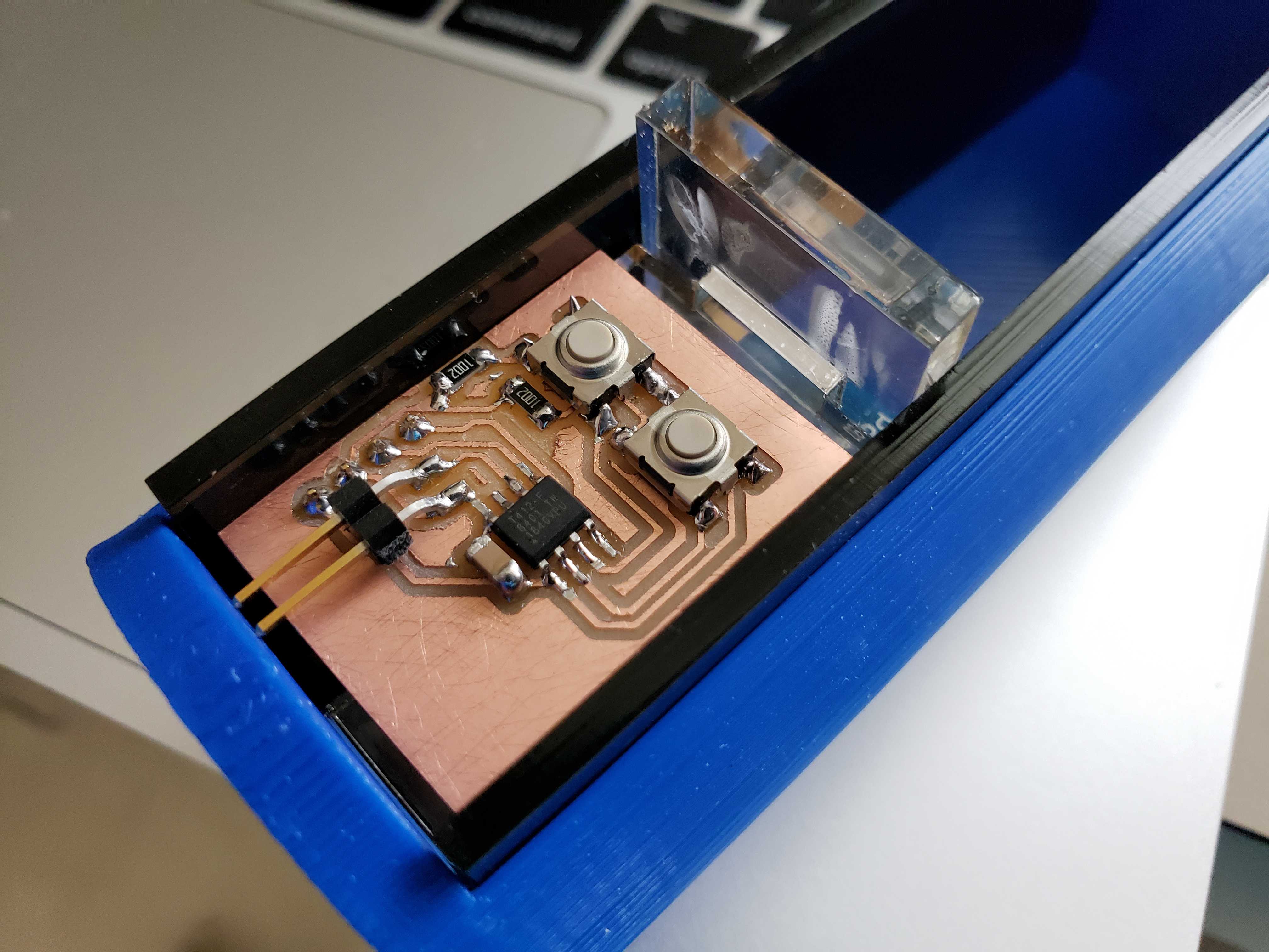
With the tracking code in place, I designed the auxilary board that would house the buttons and communicate to the master board through I2C. I used the ATTiny412 for this role because it was small, abundant, and enough for the purpose of polling the buttons.


A word of caution for future readers. You cannot share pull down resistors among buttons! I almost would have wasted precious time attempting to debug an electrical problem if I hadn’t done my research first and seen this thread.
Good

Bad

The Wire documentation provided the useful functions to setup master and slave funcitonality. The Master uses the requestFrom() function to invoke the requestEvent() function. I added the receiveEvent() function as well for debugging purposes.
Master Code
#include <Wire.h>

void setup() {
  // put your setup code here, to run once:
  Wire.begin();
  Wire.setClock(400000L);
  Serial.begin(9600);
}

void loop() {
  Wire.requestFrom((byte)0x04, 1, true);
  byte incoming = 1 << 4;
  ifs (Wire.available()) {
   Serial.println("Wire Available");
   incoming = Wire.read();
  }

  Serial.println(incoming);
  delay(100);
}
Slave Code
#include <Wire.h>
#include <avr/io.h>

#define setInputPin(pin) PORTA.DIRCLR |= (1 << pin)
#define setOutputPin(pin) PORTA.DIRSET |= (1 << pin)
#define setPinHigh(pin) VPORTA.OUT |= (1 << pin)
#define setPinLow(pin) VPORTA.OUT &= ~(1 << pin)
#define readPin(pin) VPORTA.IN & (1 << pin)

#define button1 6
#define button2 7

byte buttonState;

void setup() {
  // put your setup code here, to run once:

  Wire.begin(0x04);
  Wire.onRequest(requestEvent);
  Wire.onReceive(receiveEvent);
  Wire.setClock(400000L);

  setInputPin(button1);
  setInputPin(button2);

  buttonState = 0x04;
}

void loop() {
  //put your main code here, to run repeatedly:
  if (readPin(button1)) {
    buttonState |= 0x01;
  }
  else {
    buttonState &= ~0x01;
  }
  if (readPin(button2)) {
    buttonState |= (byte)(1 << 1);
  }
  else {
    buttonState &= (byte)~(1 << 1);
  }
}
byte getButtonState() {
  return readPin(button1);
}
void receiveEvent(int howMany) {
  Wire.read();
}
void requestEvent()
{
  Wire.write(buttonState);
}
However, the serial output showed that the master was receiving only no bytes no matter what buttons were pressed. I tried changing the type of the buttonState to no avail.
I changed to the requestEvent to only write a dummy byte. Strangely enough, the master received the correct byte. I surmised that the function couldn’t read the global variable for some reason and decided that the buttonState would be determined determined by function call instead of loop. Sure enough, the serial output reflected the button states accurately.
Dummy Byte
void requestEvent()
{
  Wire.write(0x04);
}
Refactored Button States
#include <Wire.h>
#include <avr/io.h>

#define setInputPin(pin) PORTA.DIRCLR |= (1 << pin)
#define setOutputPin(pin) PORTA.DIRSET |= (1 << pin)
#define setPinHigh(pin) VPORTA.OUT |= (1 << pin)
#define setPinLow(pin) VPORTA.OUT &= ~(1 << pin)
#define readPin(pin) VPORTA.IN & (1 << pin)

#define button1 6
#define button2 7

void setup() {
  // put your setup code here, to run once:

  Wire.begin(0x04);
  Wire.onRequest(requestEvent);
  Wire.onReceive(receiveEvent);
  Wire.setClock(400000L);

  setInputPin(button1);
  setInputPin(button2);
}

void loop() {

}
byte getButtonState() {
  byte buttonState = 0x00;
  if (readPin(button1)) buttonState |= 0x01;
  if (readPin(button2)) buttonState |= 0x02;
  return buttonState;
}
void receiveEvent(int howMany) {
  Wire.read();
}
void requestEvent()
{
  Wire.write(getButtonState());
}
I wanted to make sure that whatever events that the button state would trigger on the master board would only occur once per button press, so I added a check to see if the button was already pressed.
Final Improved Code
#include <Wire.h>
#include <avr/io.h>

#define setInputPin(pin) PORTA.DIRCLR |= (1 << pin)
#define setOutputPin(pin) PORTA.DIRSET |= (1 << pin)
#define setPinHigh(pin) VPORTA.OUT |= (1 << pin)
#define setPinLow(pin) VPORTA.OUT &= ~(1 << pin)
#define readPin(pin) VPORTA.IN & (1 << pin)

#define button1 6
#define button2 7

bool prevButton1;
bool prevButton2;

void setup() {
  // put your setup code here, to run once:
  Wire.begin(0x04);
  Wire.onRequest(requestEvent);
  Wire.setClock(400000L);
  setInputPin(button1);
  setInputPin(button2);
}
void loop() {
}
byte getButtonState() {
  byte buttonState = 0x00;
  if (readPin(button1)) {
    if (!prevButton1) {
      buttonState |= 0x01;
    }
    prevButton1 = true;
  }
  else {
    prevButton1 = false;
  }
  if (readPin(button2)) {
    if (!prevButton2) {
      buttonState |= 0x02;
    }
    prevButton2 = true;
  }
  else {
    prevButton2 = false;
  }
  return buttonState;
}
void requestEvent()
{
  Wire.write(getButtonState());
}
With the test master code functional, I could implement the UI functionality in the IMU code. I set the leftmost button to calibrate the magnometer and the rightmost button to do gyro and accelemoter calibration.
Wire.requestFrom((byte)0x04, 1, true);
byte incoming = 0x00;
if (Wire.available()) {
    incoming = Wire.read();
    if (incoming & 0x01) {
      _delay_ms(2000);
      //initAK8963(magCalibration);
      magcalMPU9250(magBias, magScale);

      Serial.print("MC ");
      Serial.print(magBias[0], 2); Serial.print(",");
      Serial.print(magBias[1], 2); Serial.print(",");
      Serial.print(magBias[2], 2); Serial.print(",");
      Serial.print(magScale[0], 2); Serial.print(",");
      Serial.print(magScale[1], 2); Serial.print(",");
      Serial.println(magScale[2], 2);

      if (SerialDebug) {
        Serial.print("DB "); Serial.println("Magnometer Bias values: ");
        Serial.print("DB "); Serial.print("X-Axis Bias "); Serial.println(magBias[0], 2);
        Serial.print("DB "); Serial.print("Y-Axis Bias "); Serial.println(magBias[1], 2);
        Serial.print("DB "); Serial.print("Z-Axis Bias "); Serial.println(magBias[2], 2);
        Serial.print("DB "); Serial.println("Magnometer Scale values: ");
        Serial.print("DB "); Serial.print("X-Axis Scale "); Serial.println(magScale[0], 2);
        Serial.print("DB "); Serial.print("Y-Axis Scale "); Serial.println(magScale[1], 2);
        Serial.print("DB "); Serial.print("Z-Axis Scale "); Serial.println(magScale[2], 2);
      }

      _delay_ms(2000);
    }
    else if (incoming & 0x02) {
      _delay_ms(2000);
      MPU9250SelfTest(SelfTest); // Start by performing self test and reporting values
      Serial.print("OC ");
      Serial.print(SelfTest[0], 1); Serial.print(",");
      Serial.print(SelfTest[1], 1); Serial.print(",");
      Serial.print(SelfTest[2], 1); Serial.print(",");
      Serial.print(SelfTest[3], 1); Serial.print(",");
      Serial.print(SelfTest[4], 1); Serial.print(",");
      Serial.println(SelfTest[5], 1);

      if (SerialDebug) {
        Serial.print("DB "); Serial.print("x-axis self test: acceleration trim within : "); Serial.print(SelfTest[0], 1); Serial.println("% of factory value");
        Serial.print("DB "); Serial.print("y-axis self test: acceleration trim within : "); Serial.print(SelfTest[1], 1); Serial.println("% of factory value");
        Serial.print("DB "); Serial.print("z-axis self test: acceleration trim within : "); Serial.print(SelfTest[2], 1); Serial.println("% of factory value");
        Serial.print("DB "); Serial.print("x-axis self test: gyration trim within : "); Serial.print(SelfTest[3], 1); Serial.println("% of factory value");
        Serial.print("DB "); Serial.print("y-axis self test: gyration trim within : "); Serial.print(SelfTest[4], 1); Serial.println("% of factory value");
        Serial.print("DB "); Serial.print("z-axis self test: gyration trim within : "); Serial.print(SelfTest[5], 1); Serial.println("% of factory value");
      }
      calibrateMPU9250(gyroBias, accelBias); // Calibrate gyro and accelerometers, load biases in bias registers
      _delay_ms(1000);
      initMPU9250();
    }
}
Using the UI board, I can redo magnometer calibration with the click of a button wheras before I had to cycle power to the entire power. Since magnometer calibration values are specific to the environment, I only needed to find a good set of calibration values and then I could hardcode the values.
magBias[0] = +24.93;  // User environmental x-axis correction in milliGauss, should be automatically calculated
magBias[1] = +188.10;  // User environmental x-axis correction in milliGauss
magBias[2] = -454.67;  // User environmental x-axis correction in milliGauss

magScale[0] = 1.09;
magScale[1] = 1.08;
magScale[2] = .94;
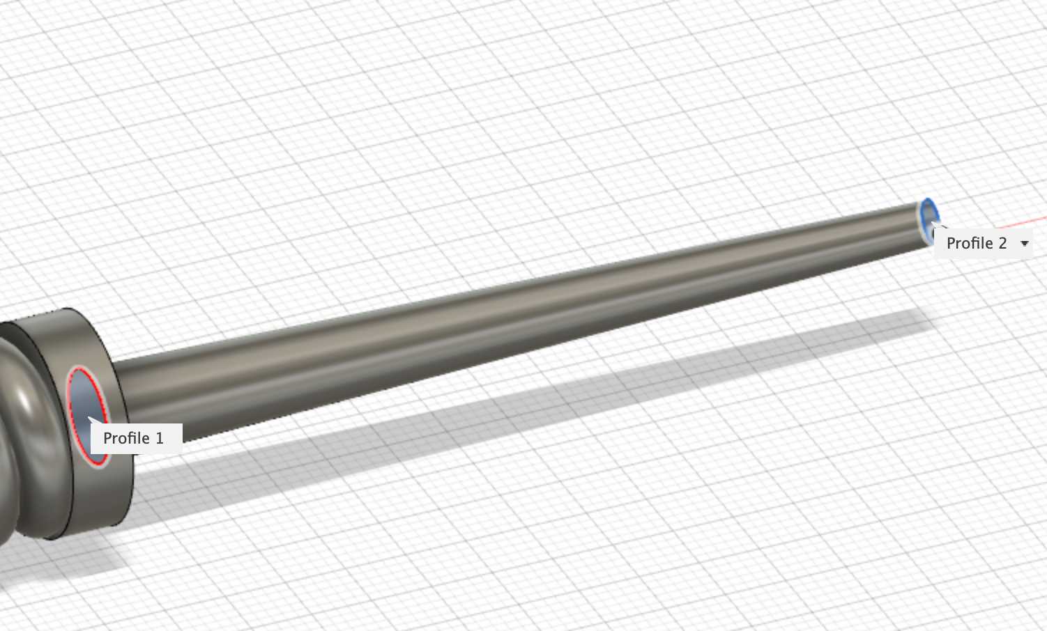
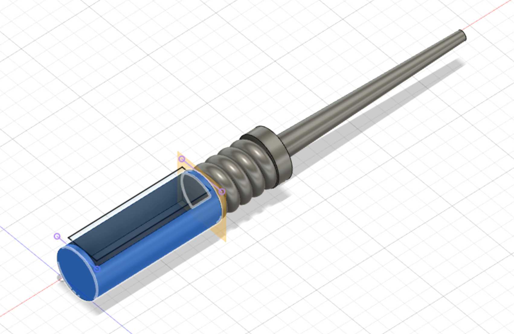
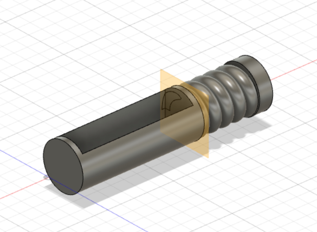
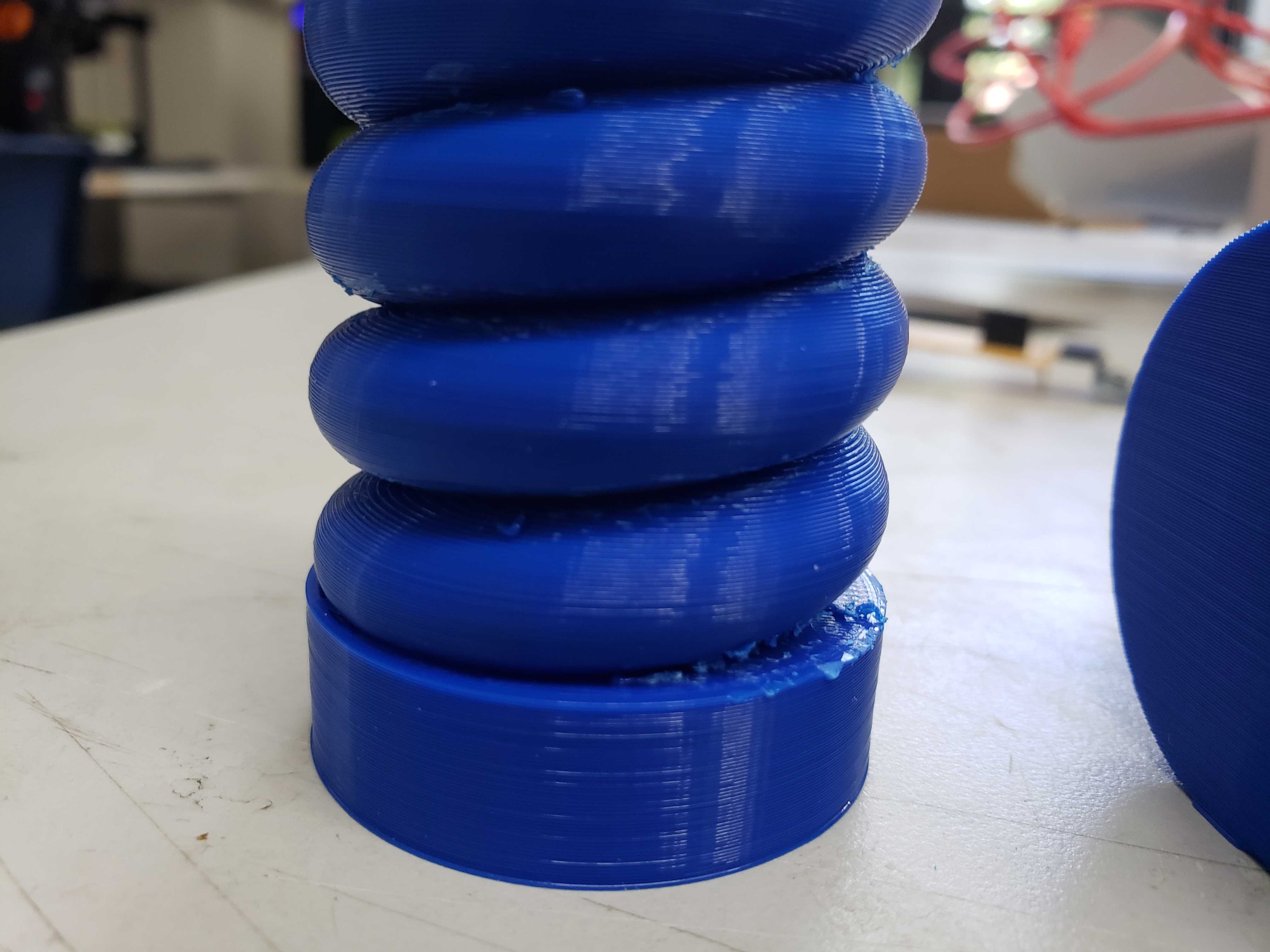
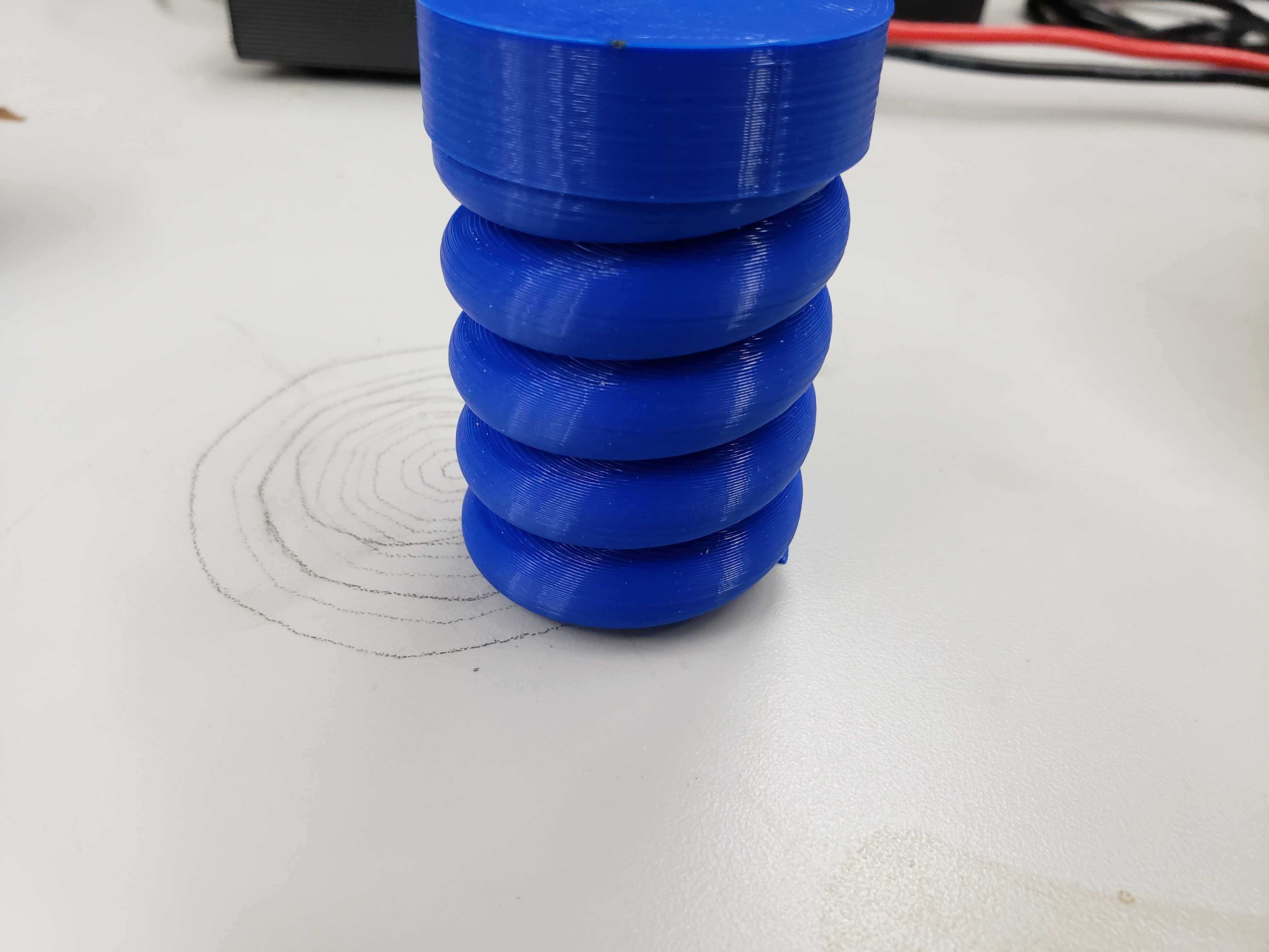
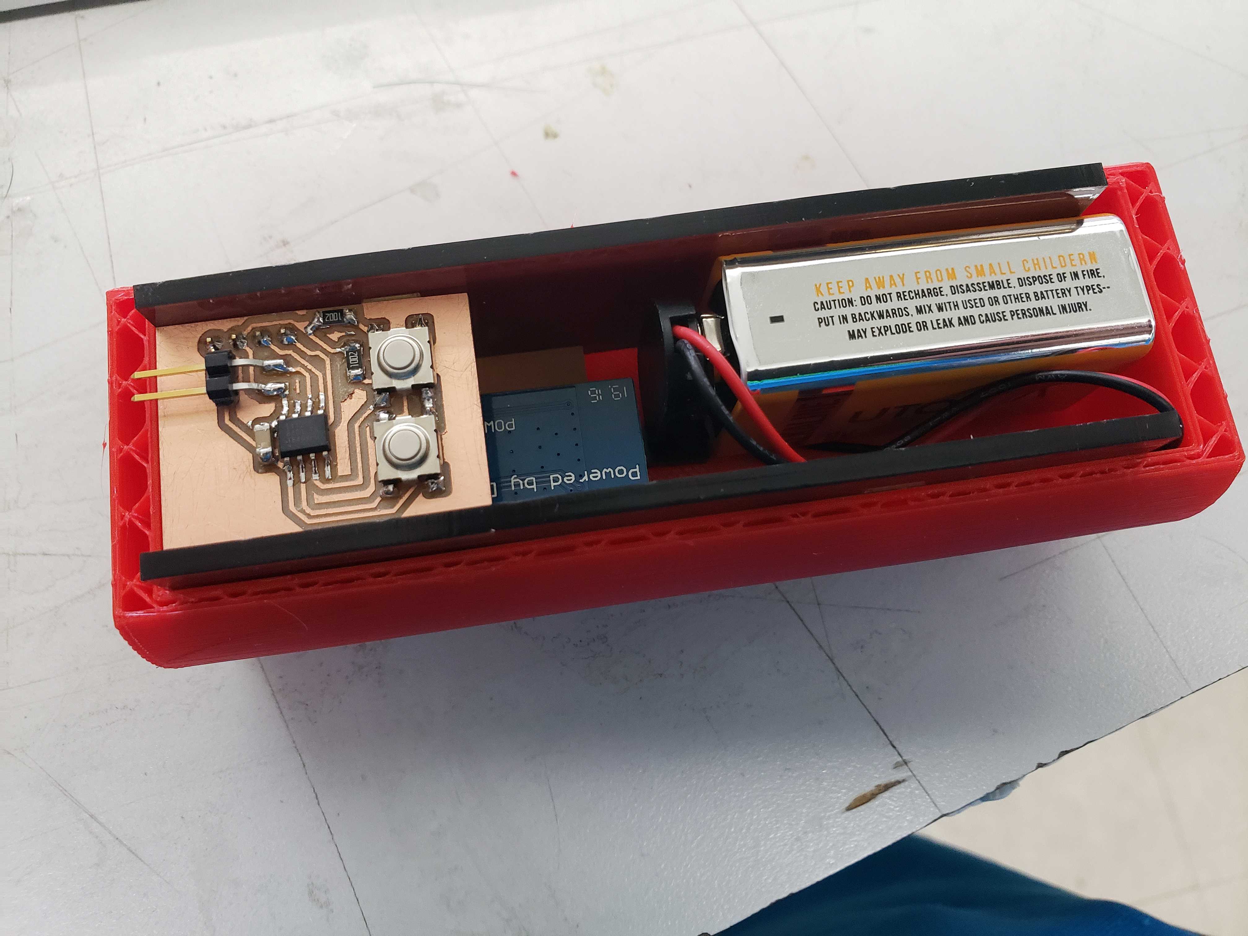
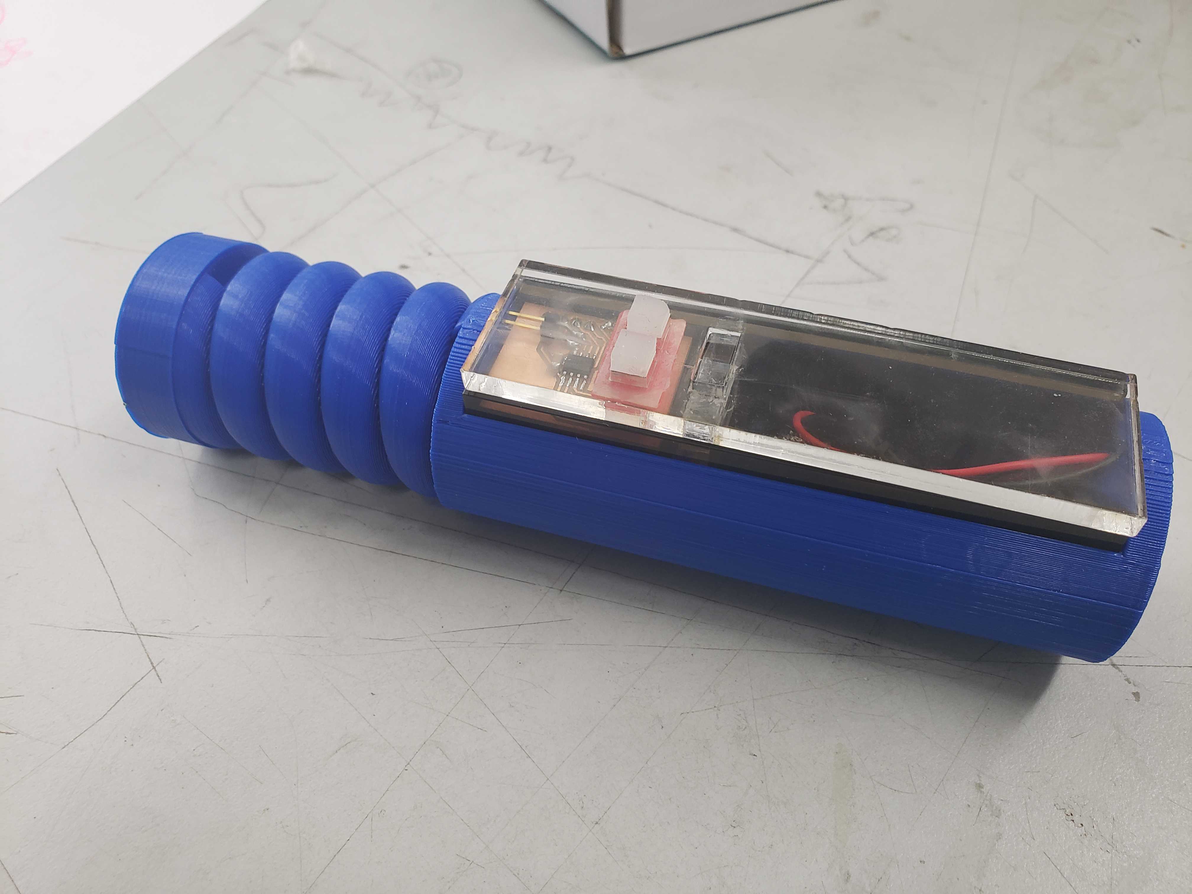
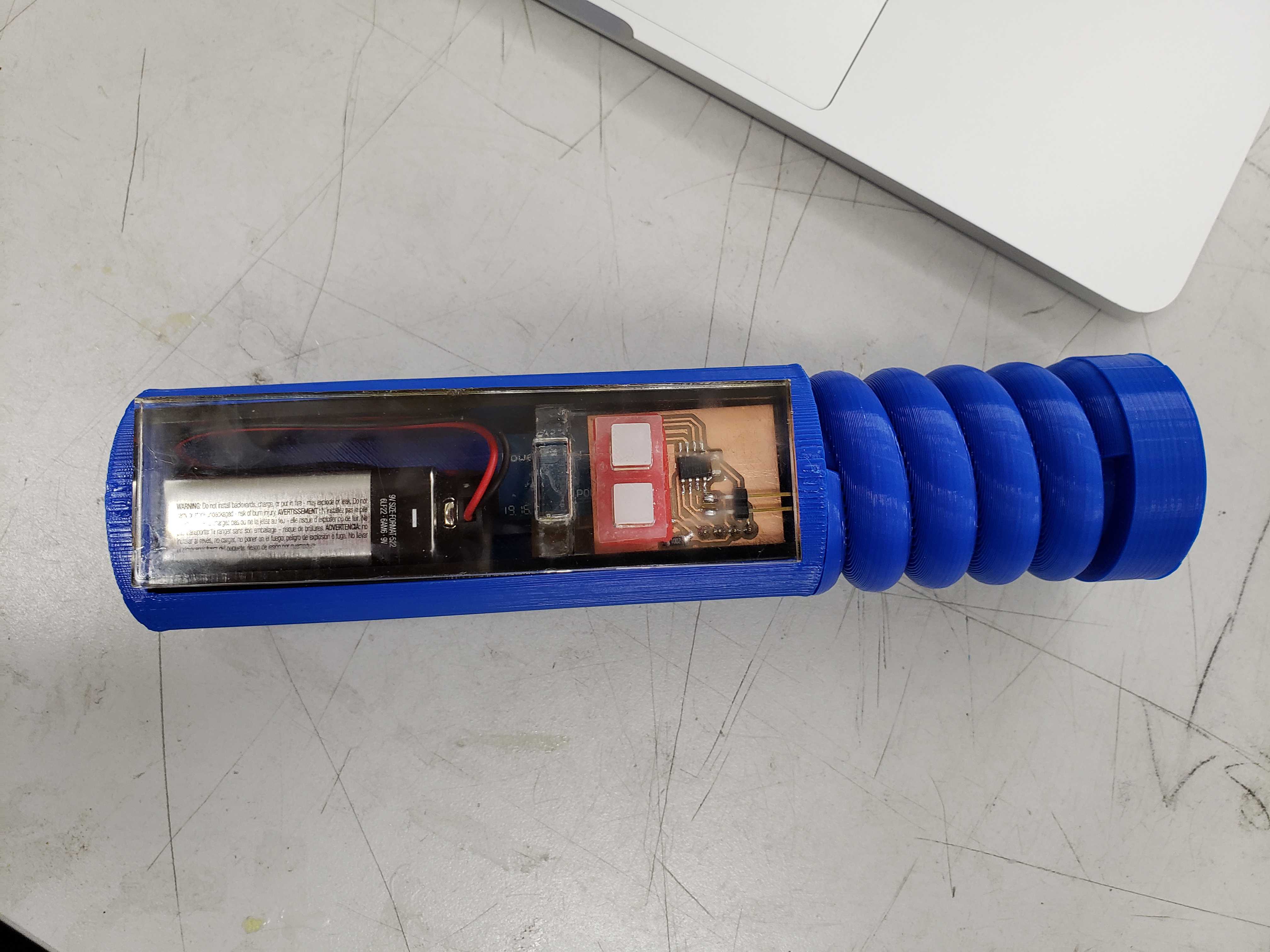
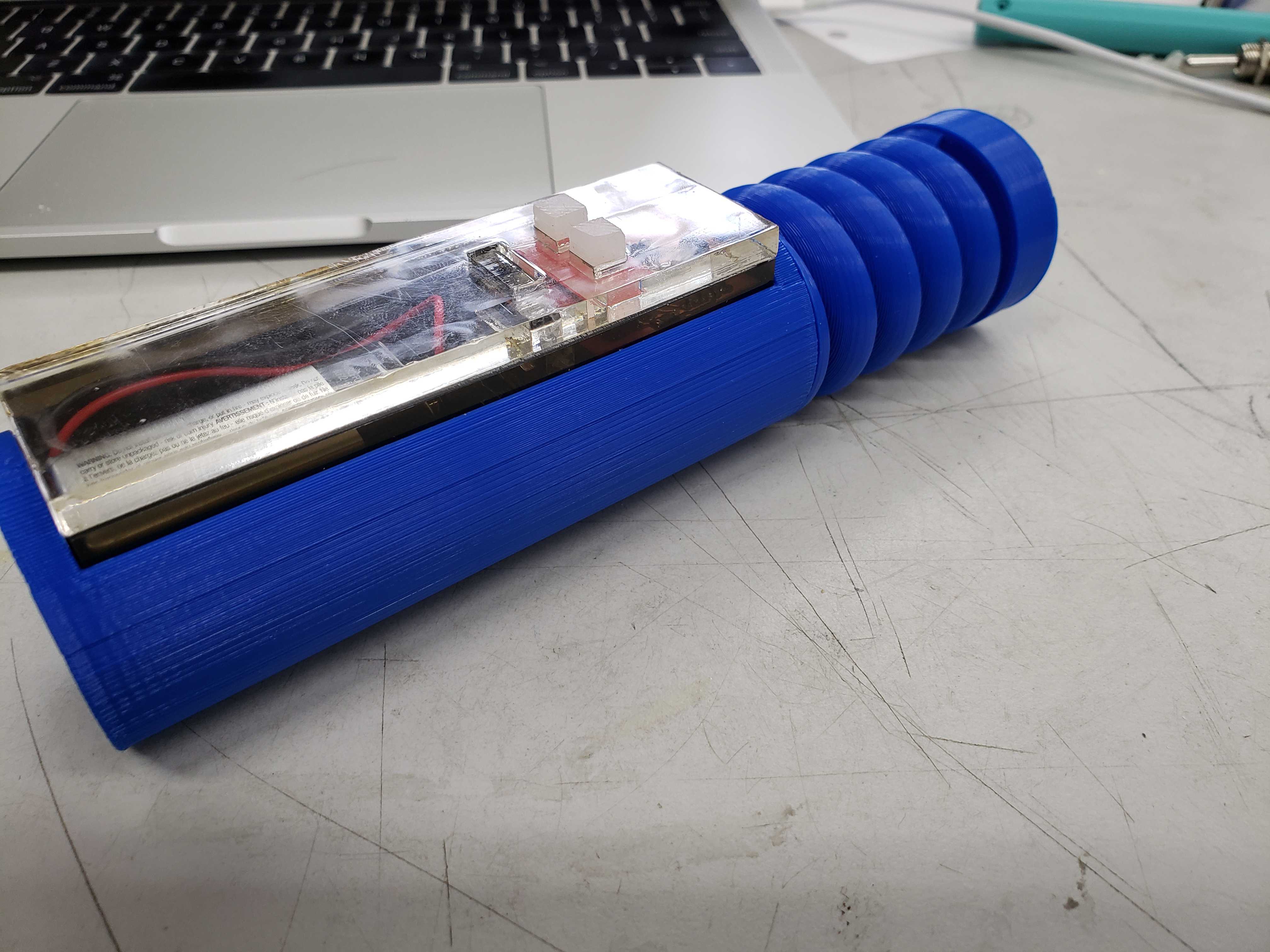
Wand Body
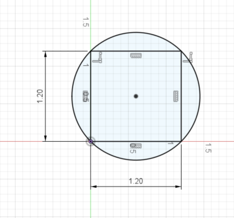
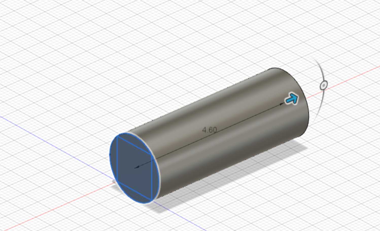
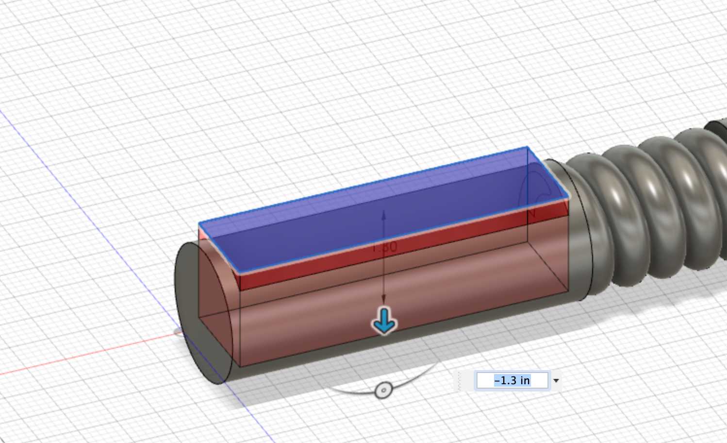
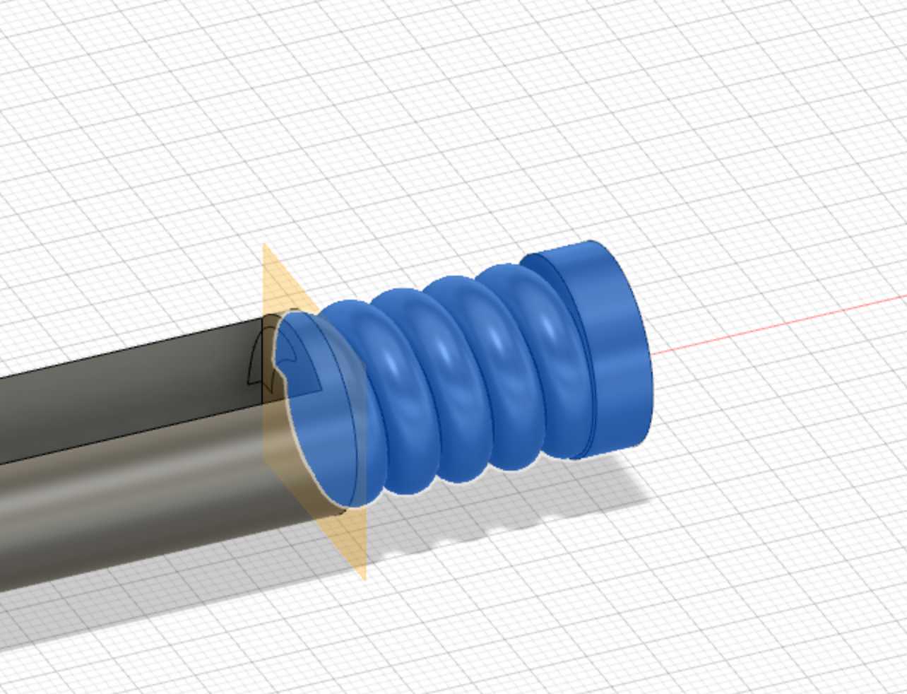
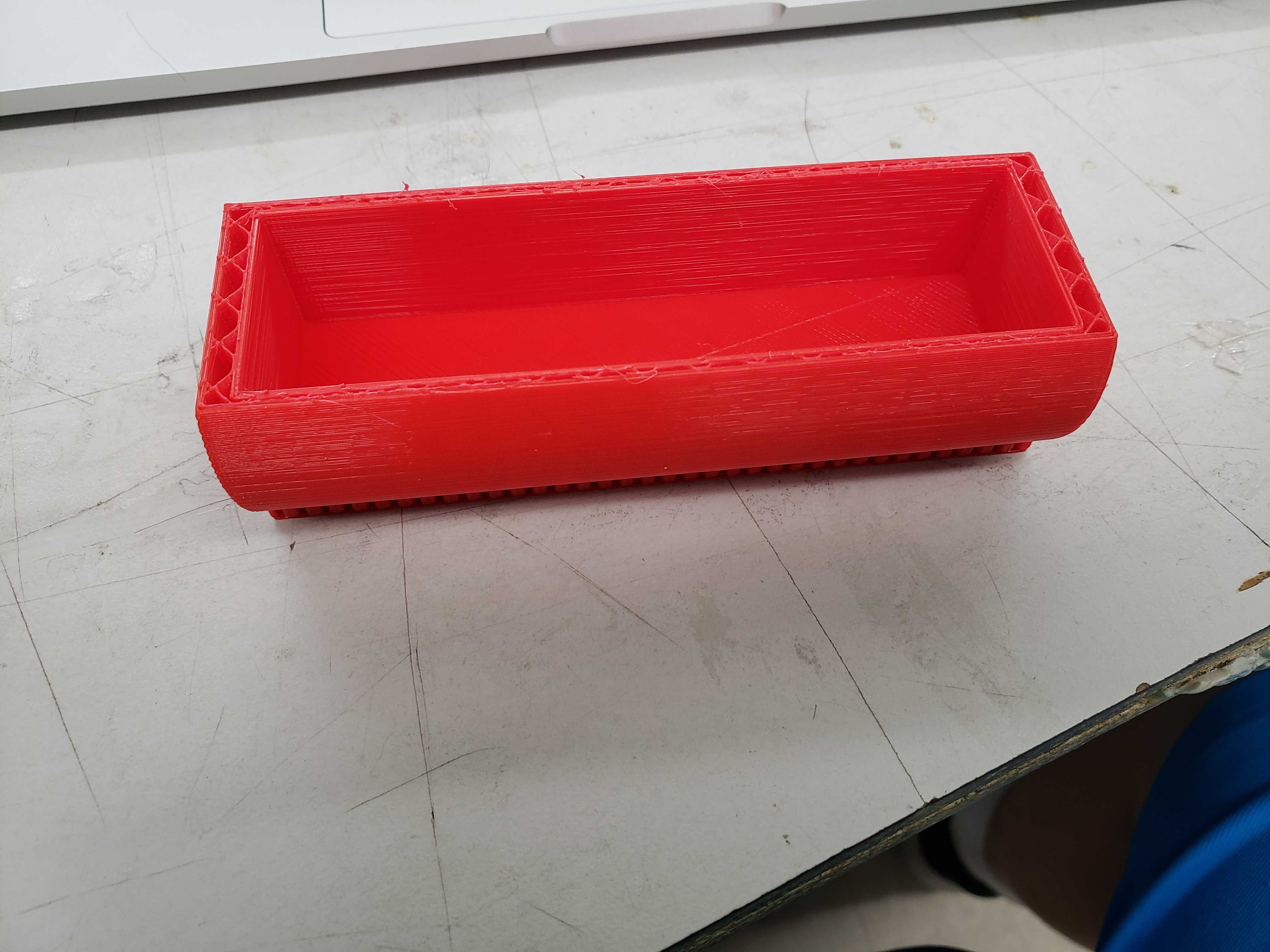
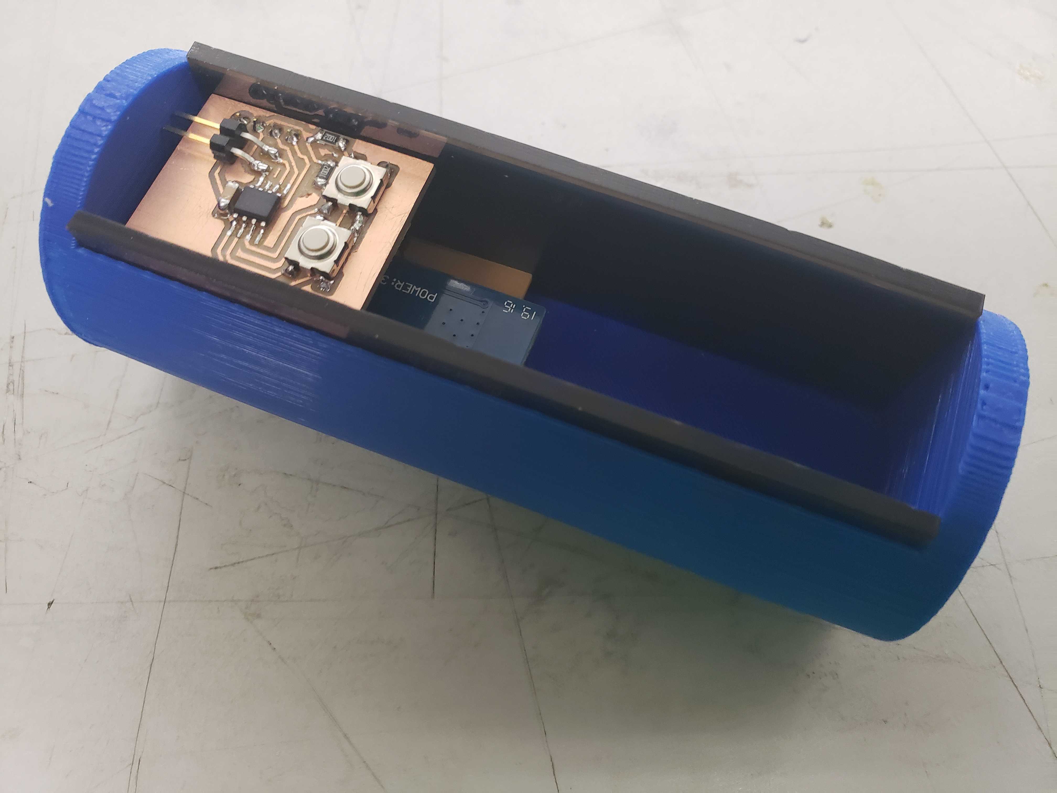
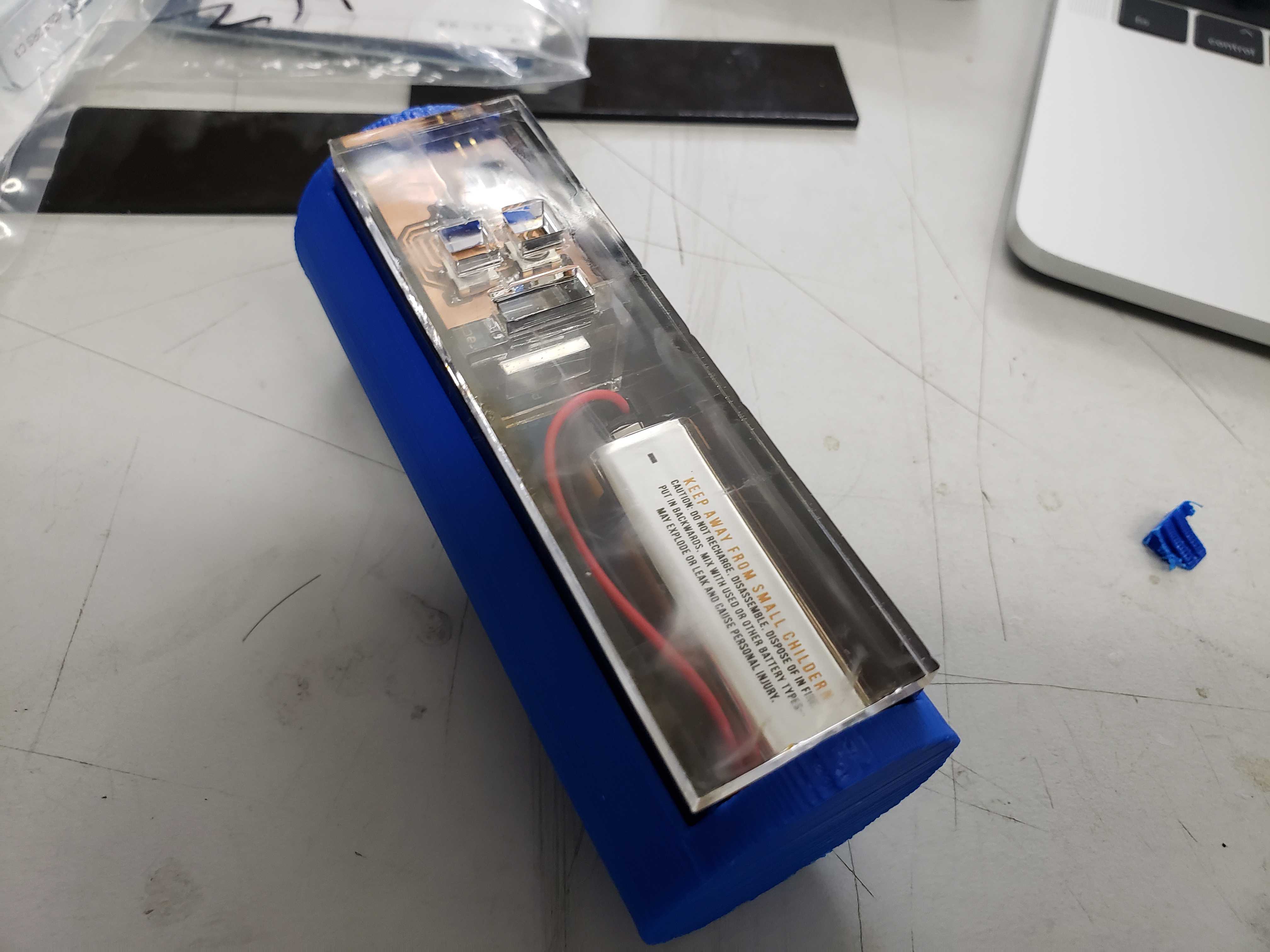
I created the length and profile of wand body by utilizing the caliper measurement of the total length, width, and height of the board + battery + wall thickness with some tolerances. I also added a spiral top and tip to the wand body as a poor artist’s attempt to make the wand resemble a fictional wand. I ended up not adding the tip as I realized that the long tip would make the wand extremely unwieldly to use.
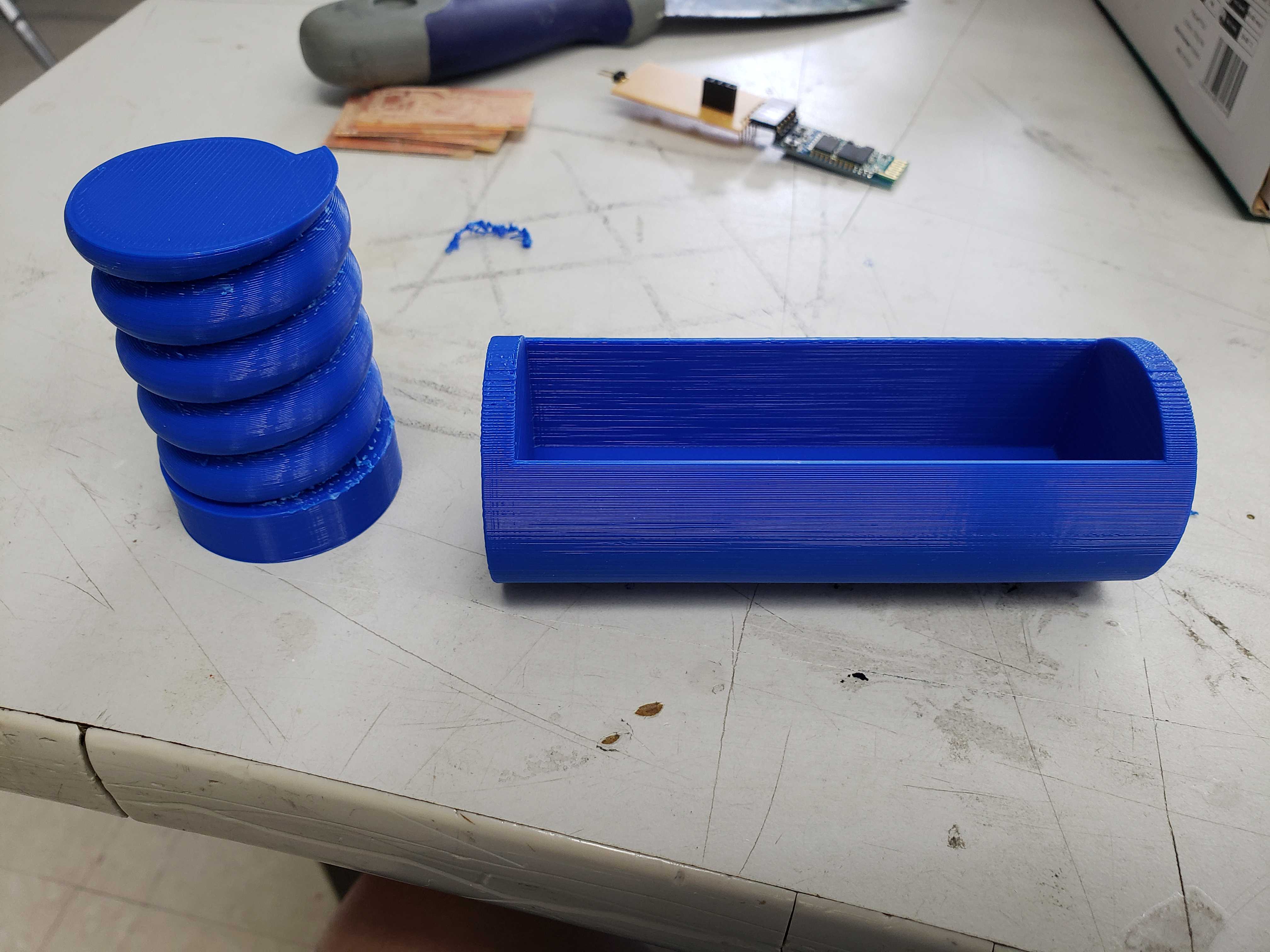
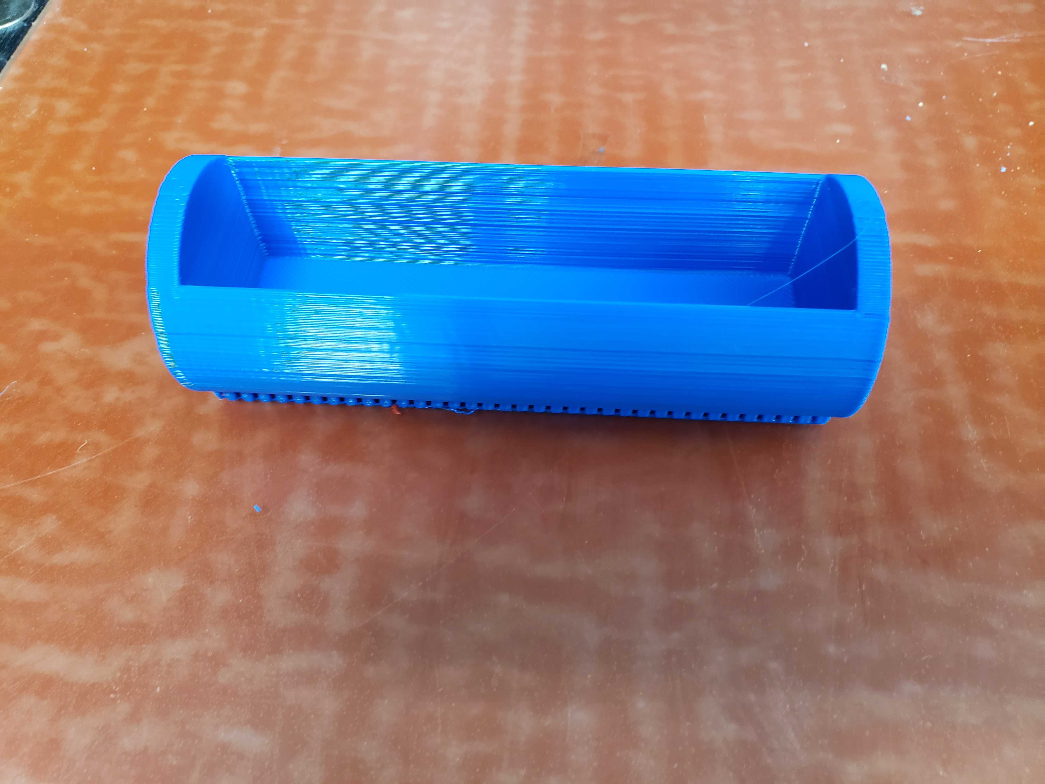
I printed out the wand body and I attempted to fit the circuitry and the battery into the cavity. However, I failed to account for the space of the battery connector. In addition, I printed the spiral top with supports, which left behind annoyinf pieces of plastics when I tried to remove the supports. I reprinted the wand with the additional space for the spacer and no supports for the spiral top. The wand body print failed, but it allowed me to check if the print was aactually the right dimensions. After confiring with the failed print, I printed the new wand body again. The spiral top print turned out extremely polished.
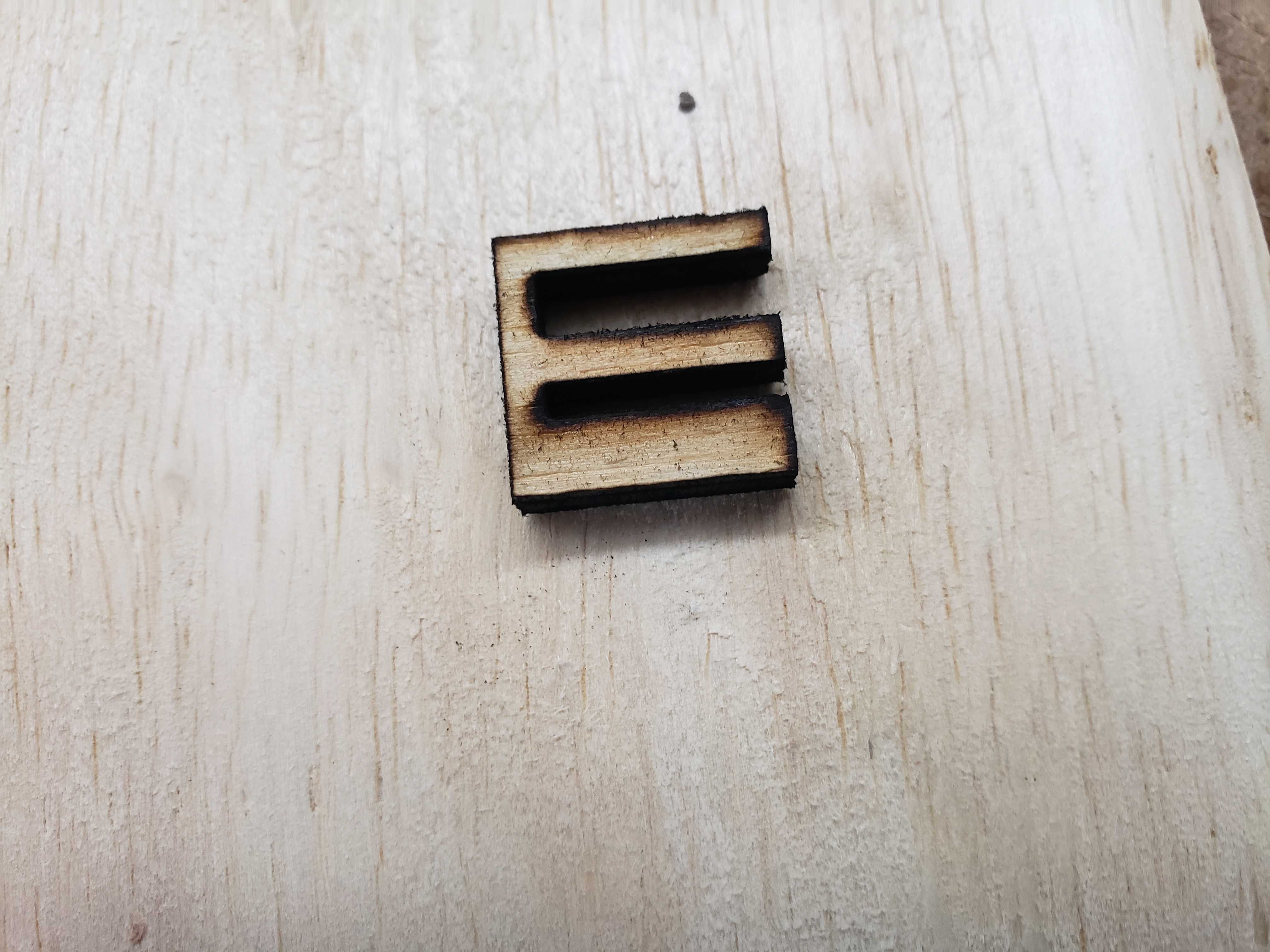
Then, I decided to design and laser cut vertical spacers for holding the IMU and Bluetooth module in place and supporting the UI board when someone applies pressure on the buttons. Unfortunately, the small size of the spacers meant that laser would cause significant warping on the spacers. Also, the flex of the parts make caliper measurements inaccurate.
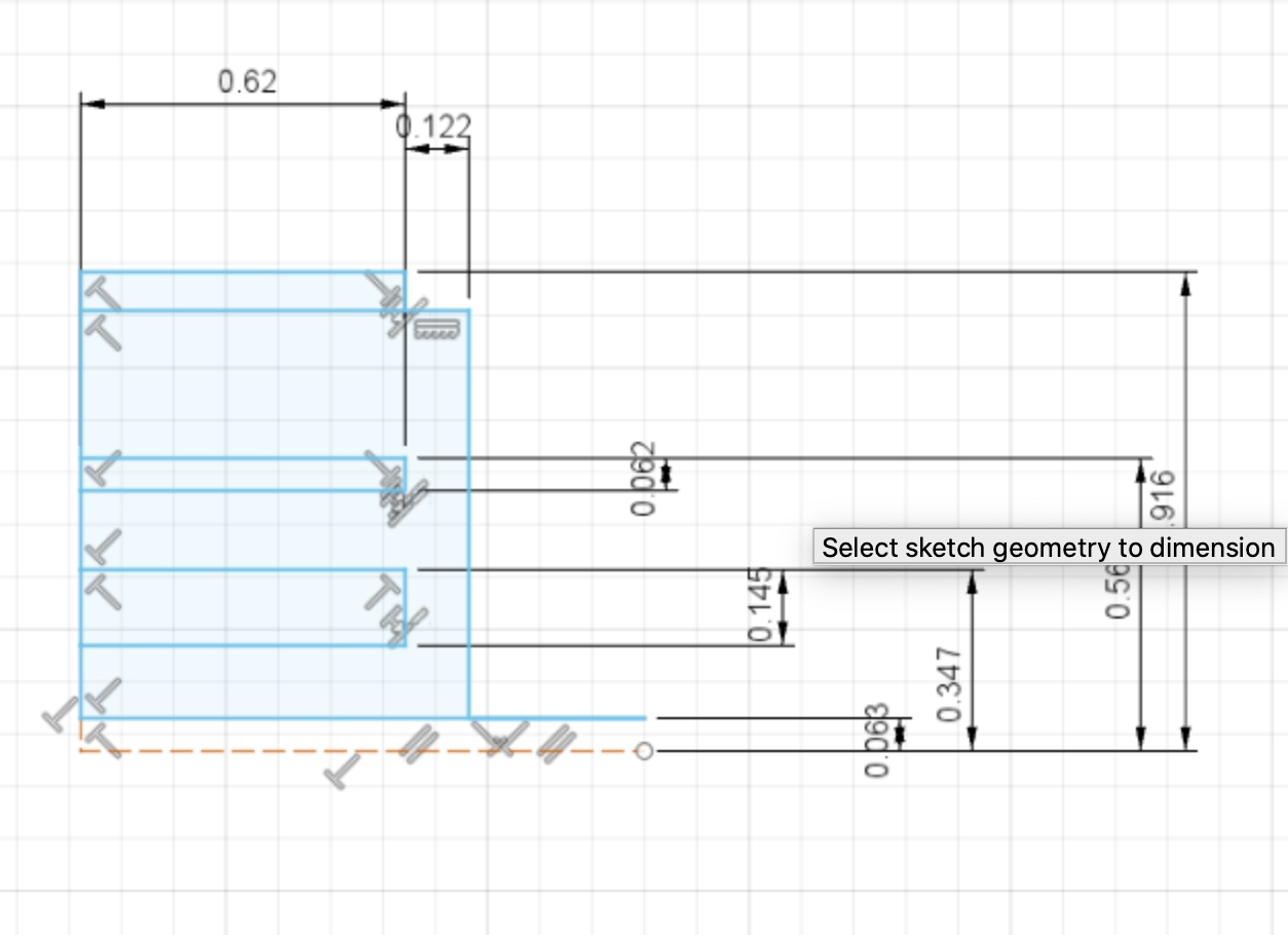
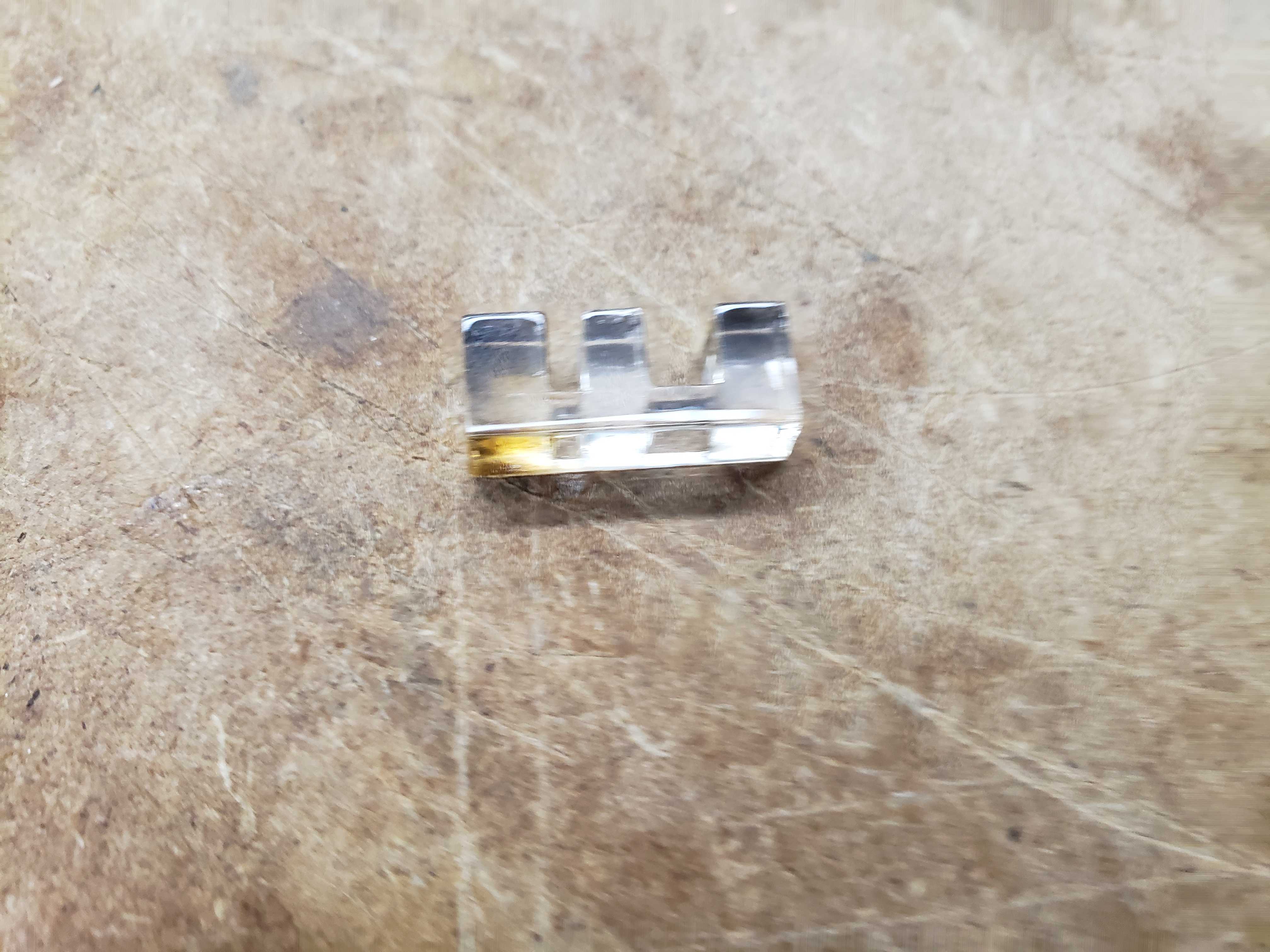
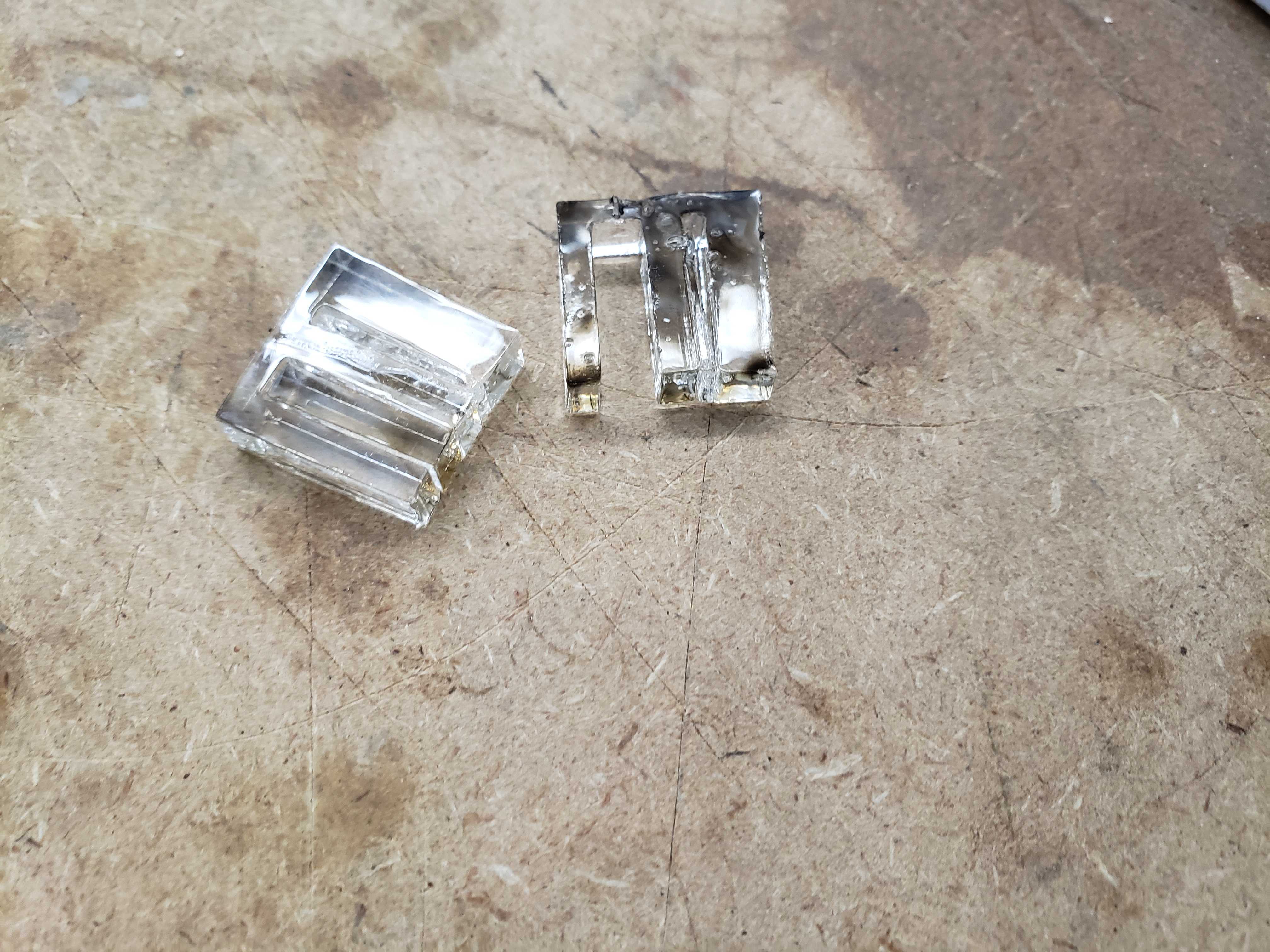
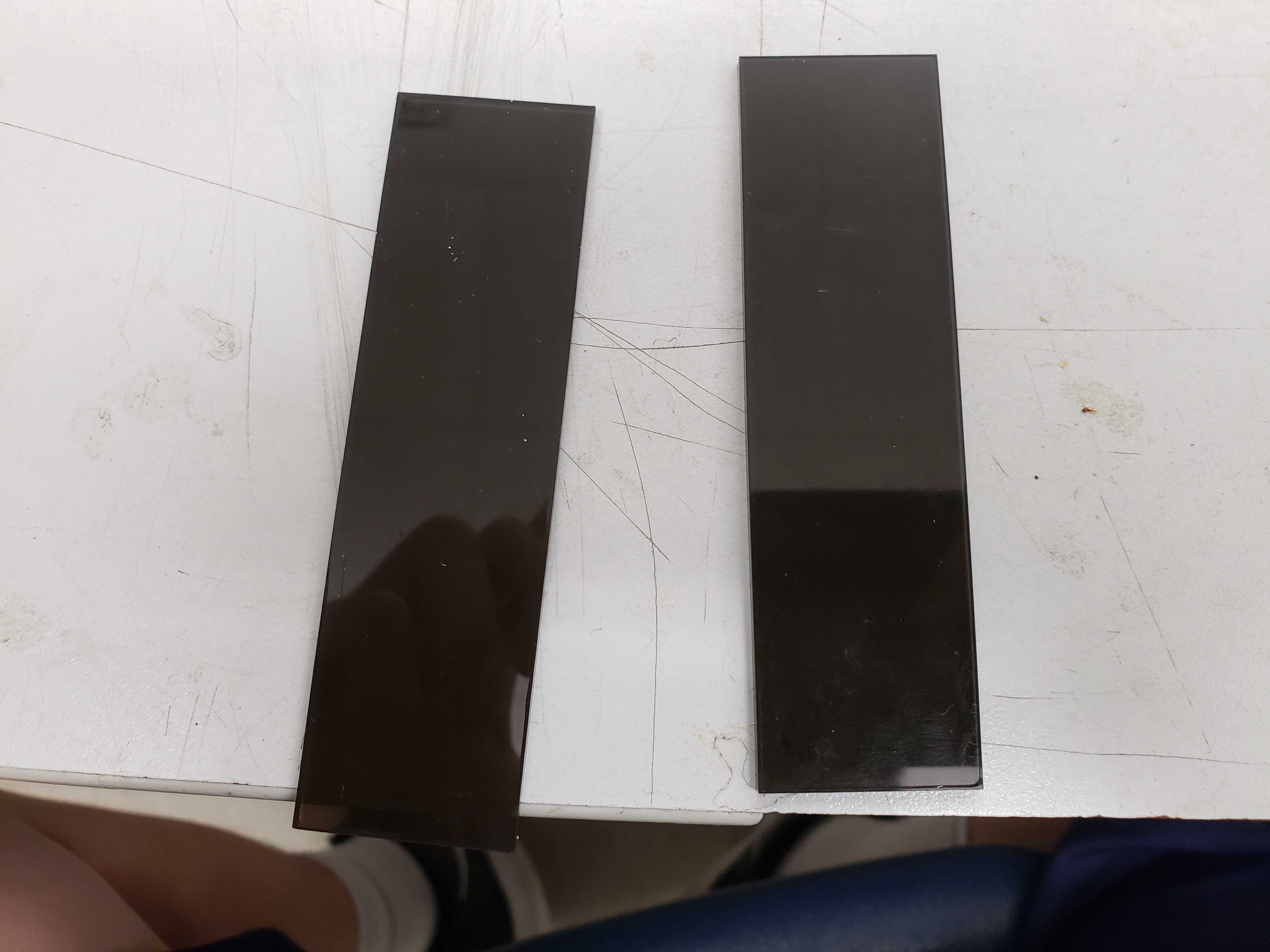
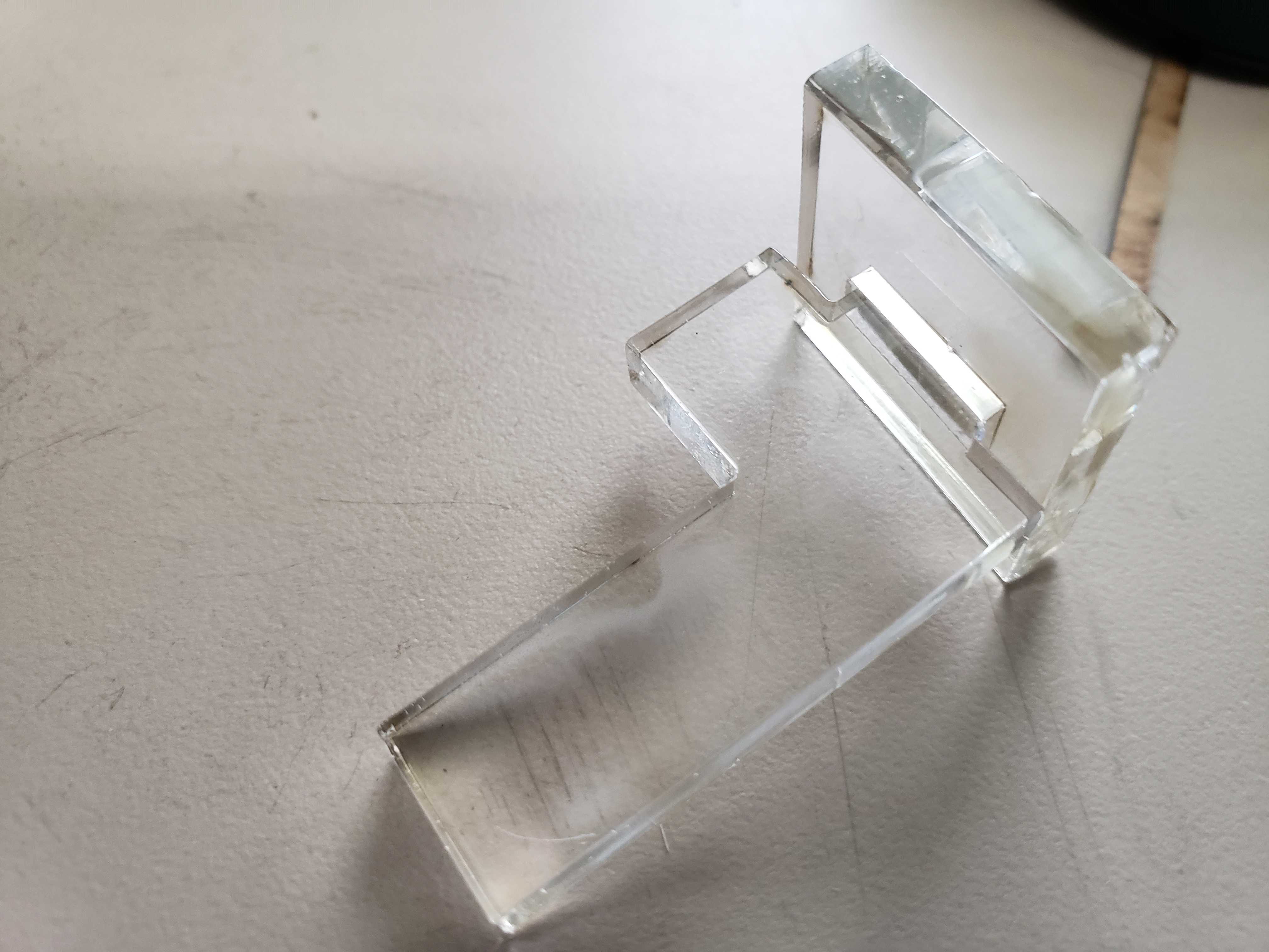
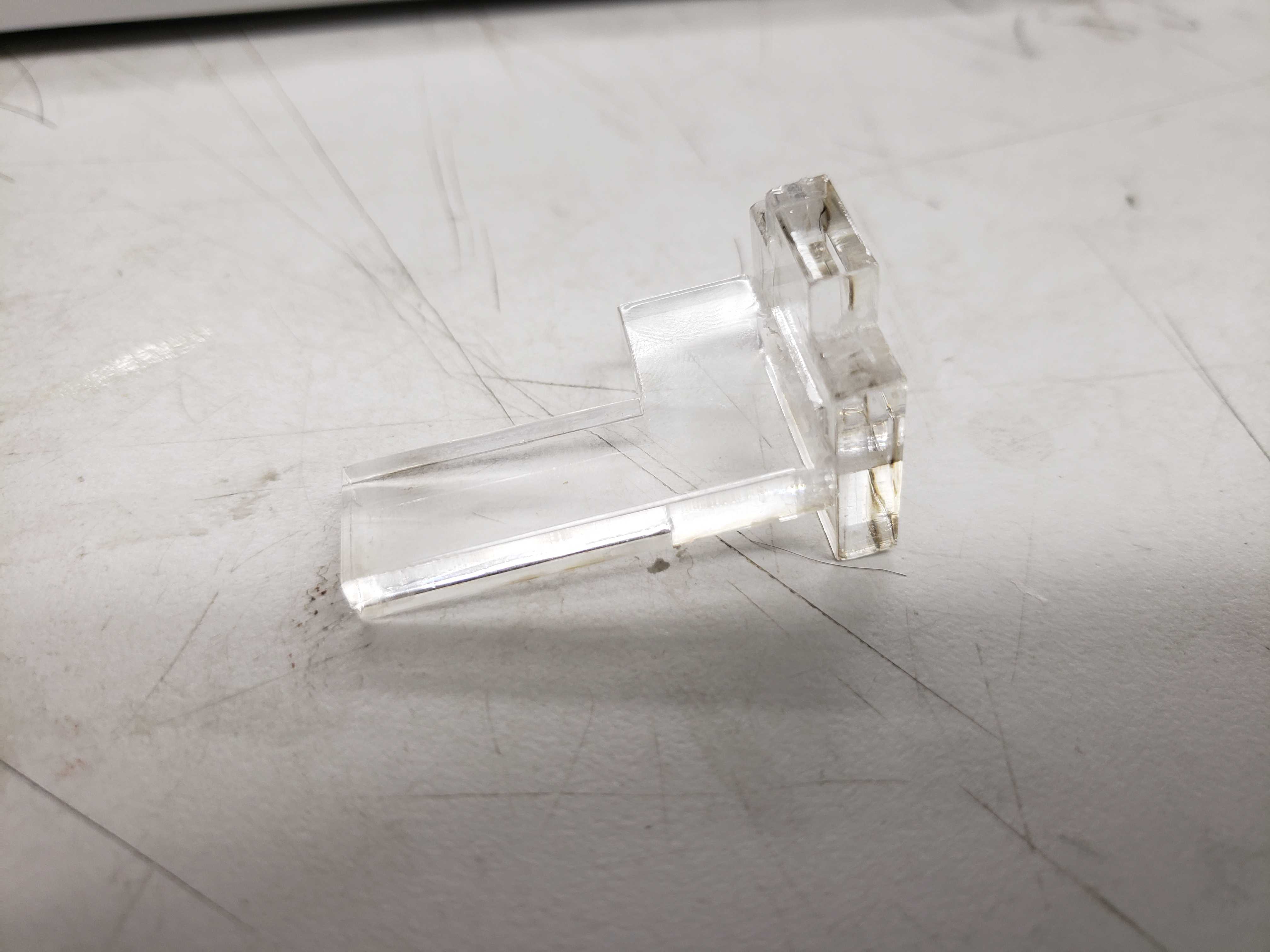
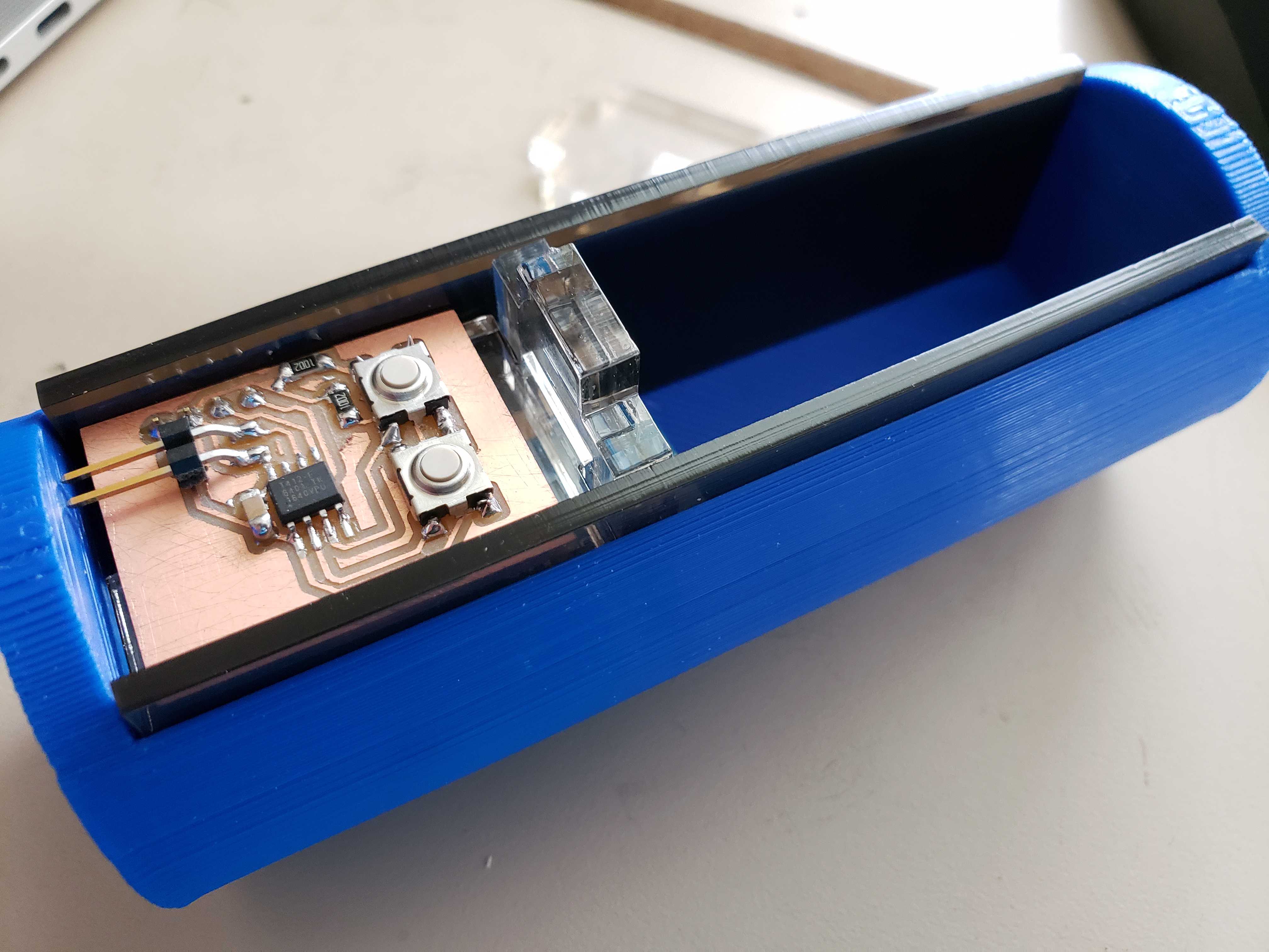
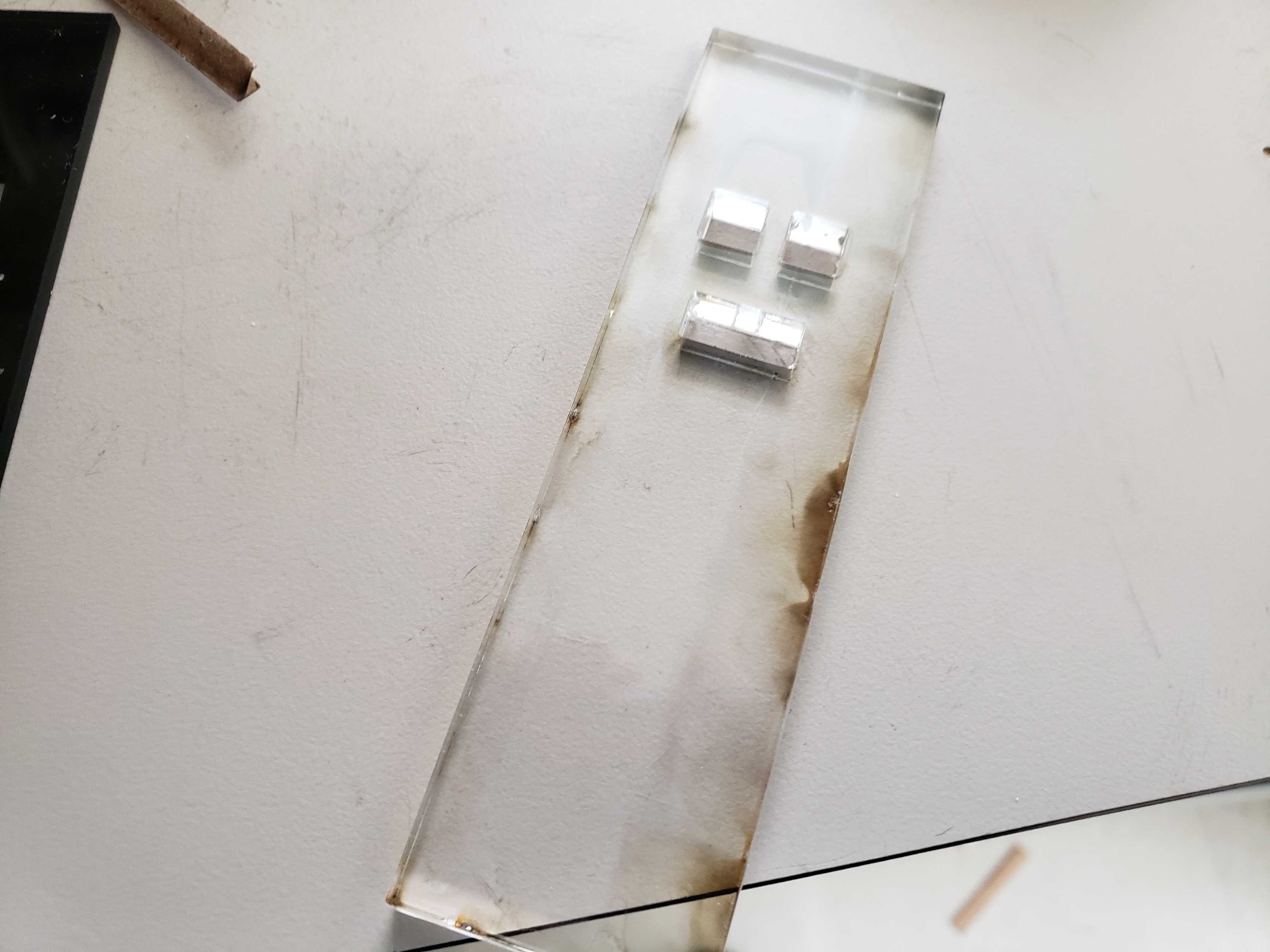
I ditched the spacer in favor of a new idea which was to use an acyrllic peice with approxamtely the same thickness as the space between the IMU and the UI board. I found some .20 in. thickness aryllic and I sketched then profile of the piece. I wanted to the piece to connect to the wand face, so I sketched a connection piece and added a slot to the wand face. The connection piece took some trial and error as I first created a connection piece flush with the wand top and wide enough to employ friction to keep the piece and face in place. In addition, I found a piece of .10 in. black acryllic that secures the innards of the ward when spacing the left and right walls. I used the wand face profile without any cutouts to cut the spacers.
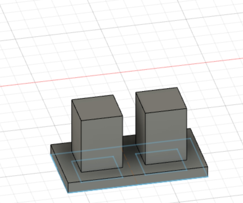
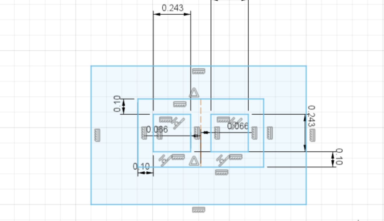
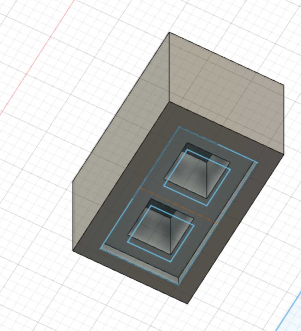
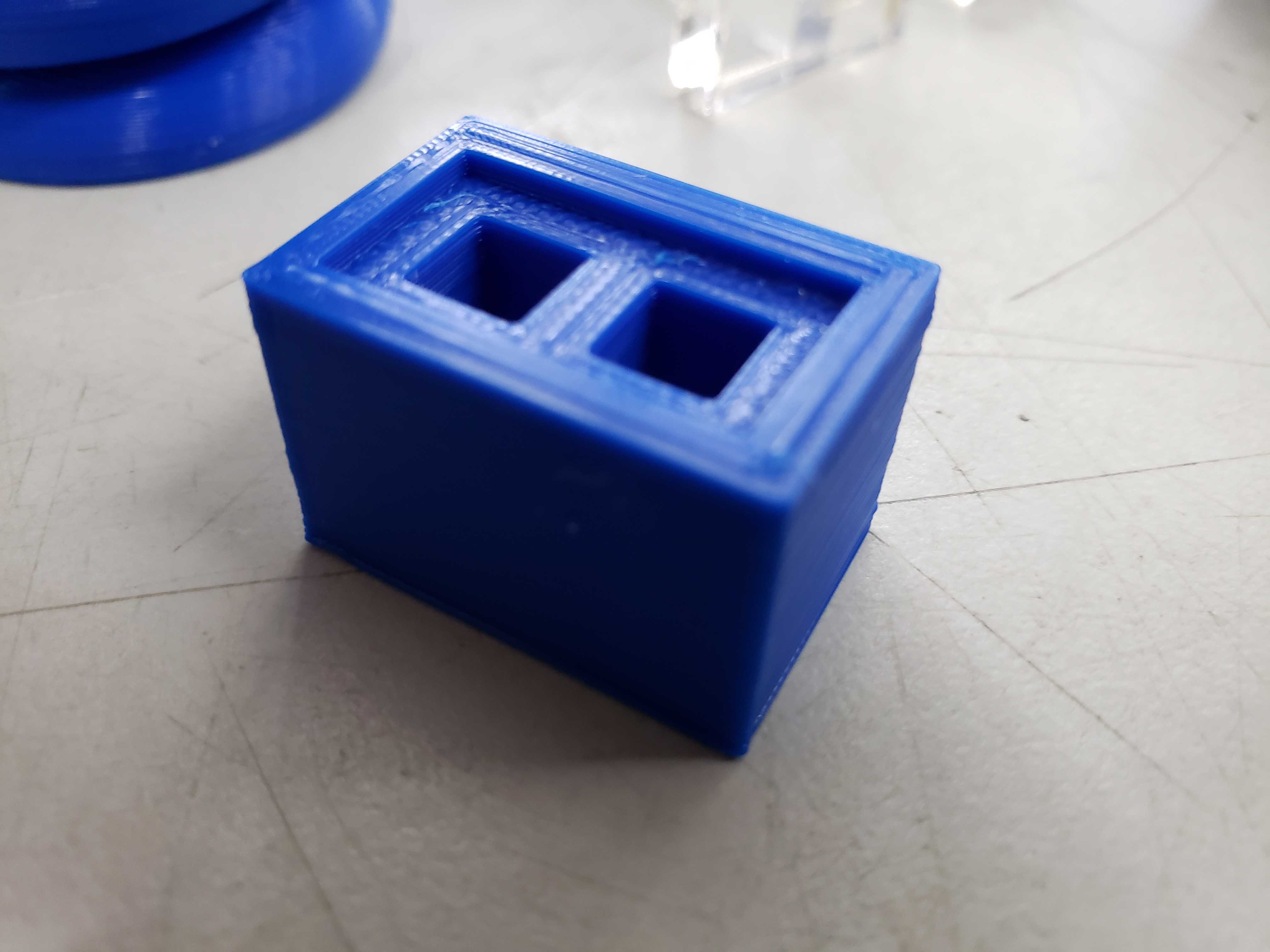
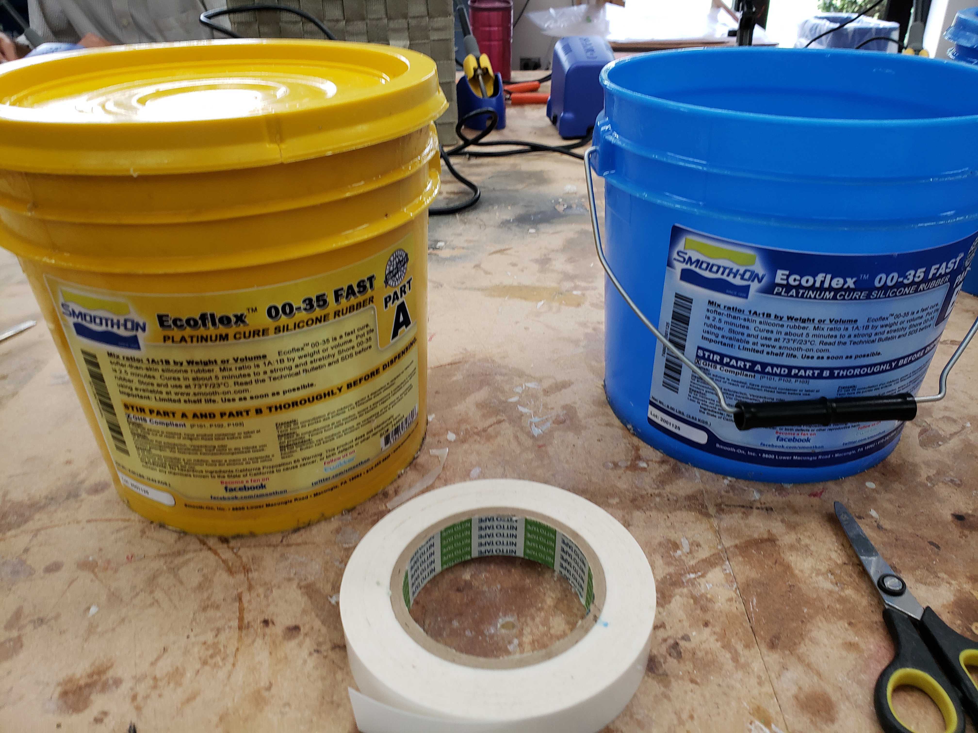
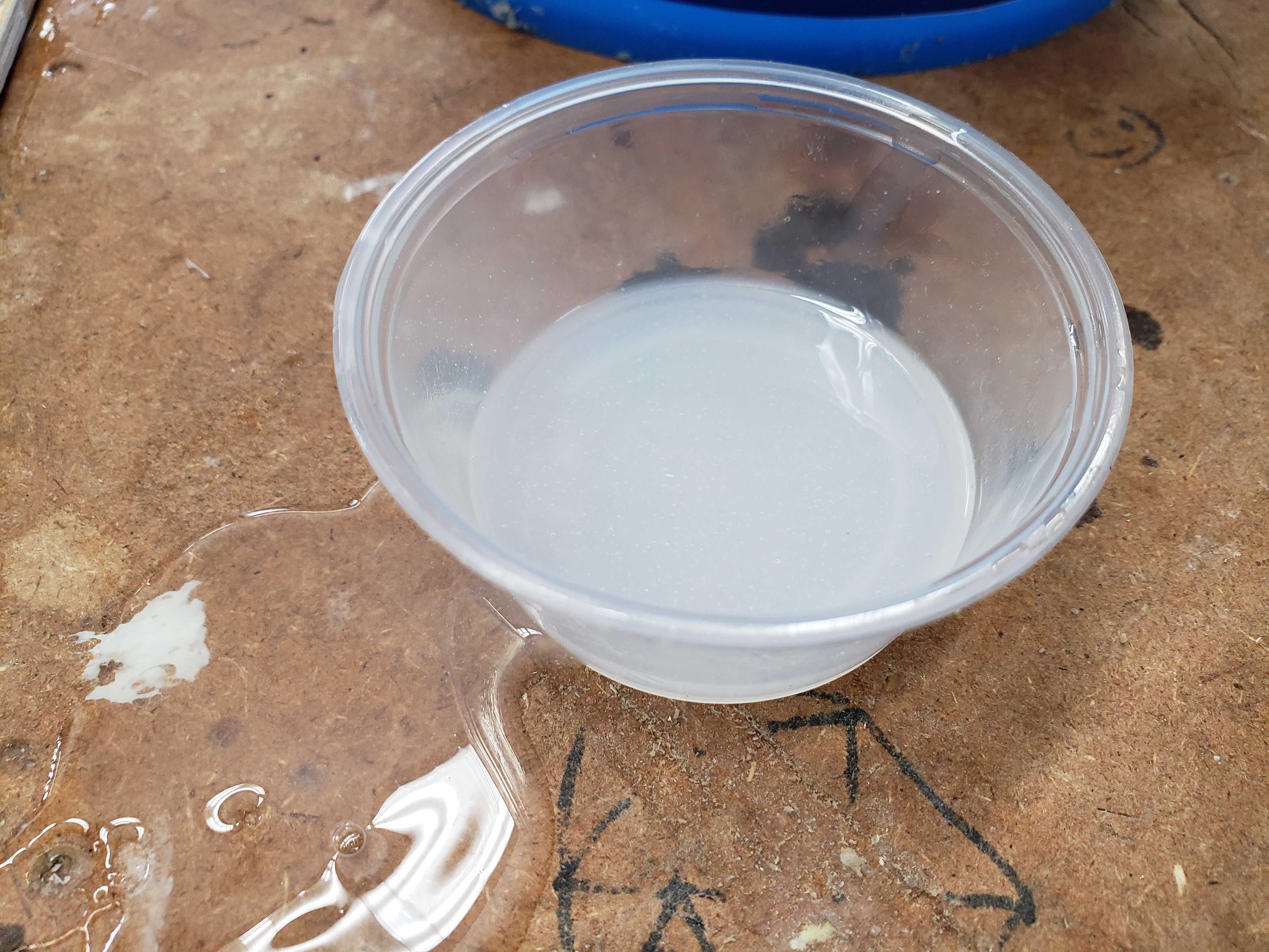
Molding and Casting
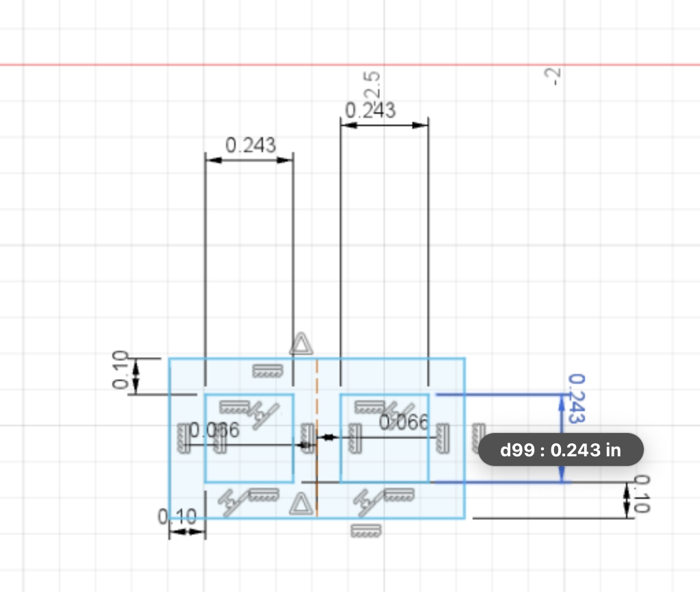
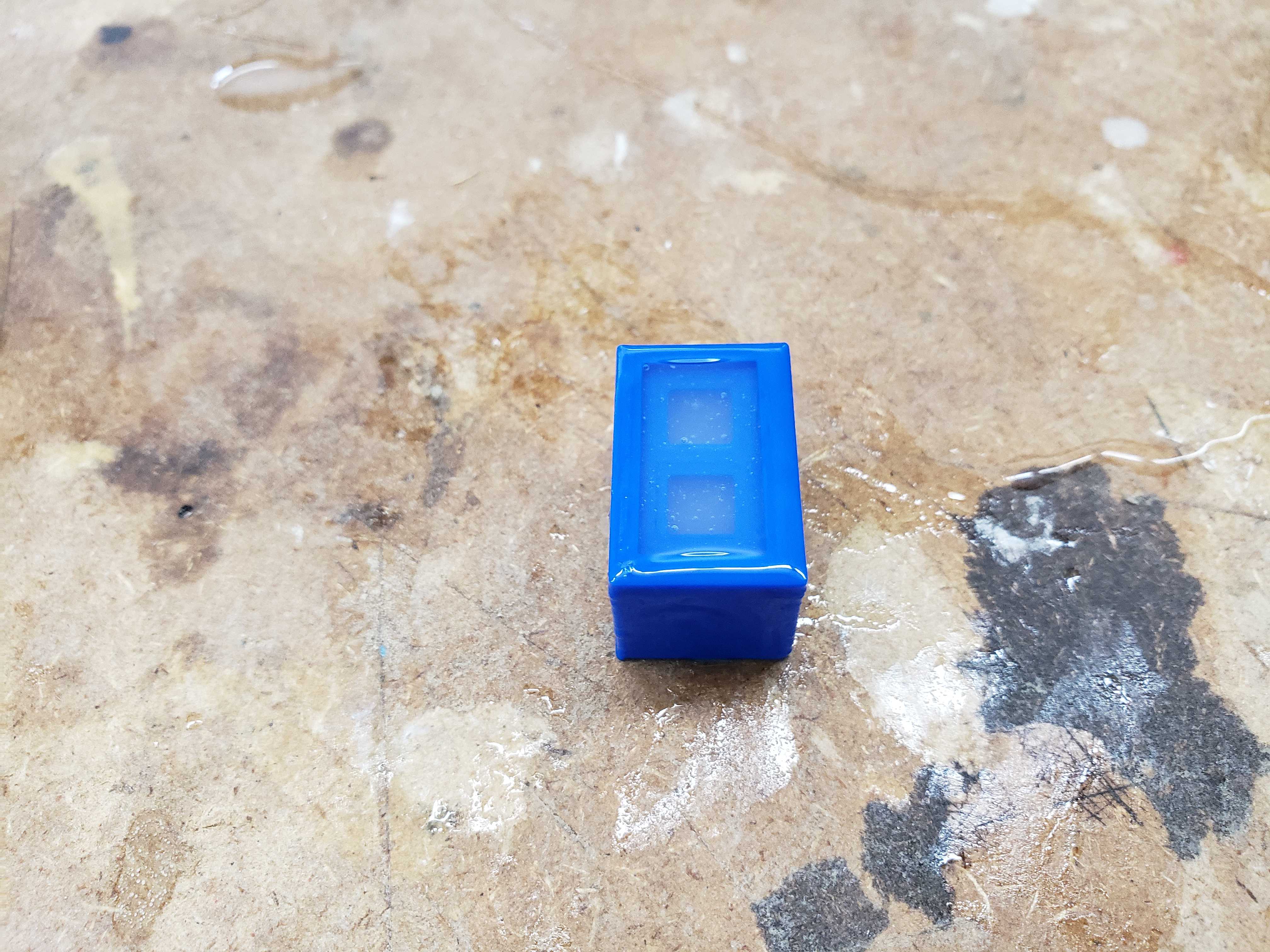
I wanted to create rubber button caps for my Omron switches so I modeled a 3D model of the mold using caliper measurements. The bottom is offset from the button caps in order to hold the button caps together and prevent the button caps from being pulled out of the wand face. I 3D printed the model and used Ecoflex to create the button cap mold.
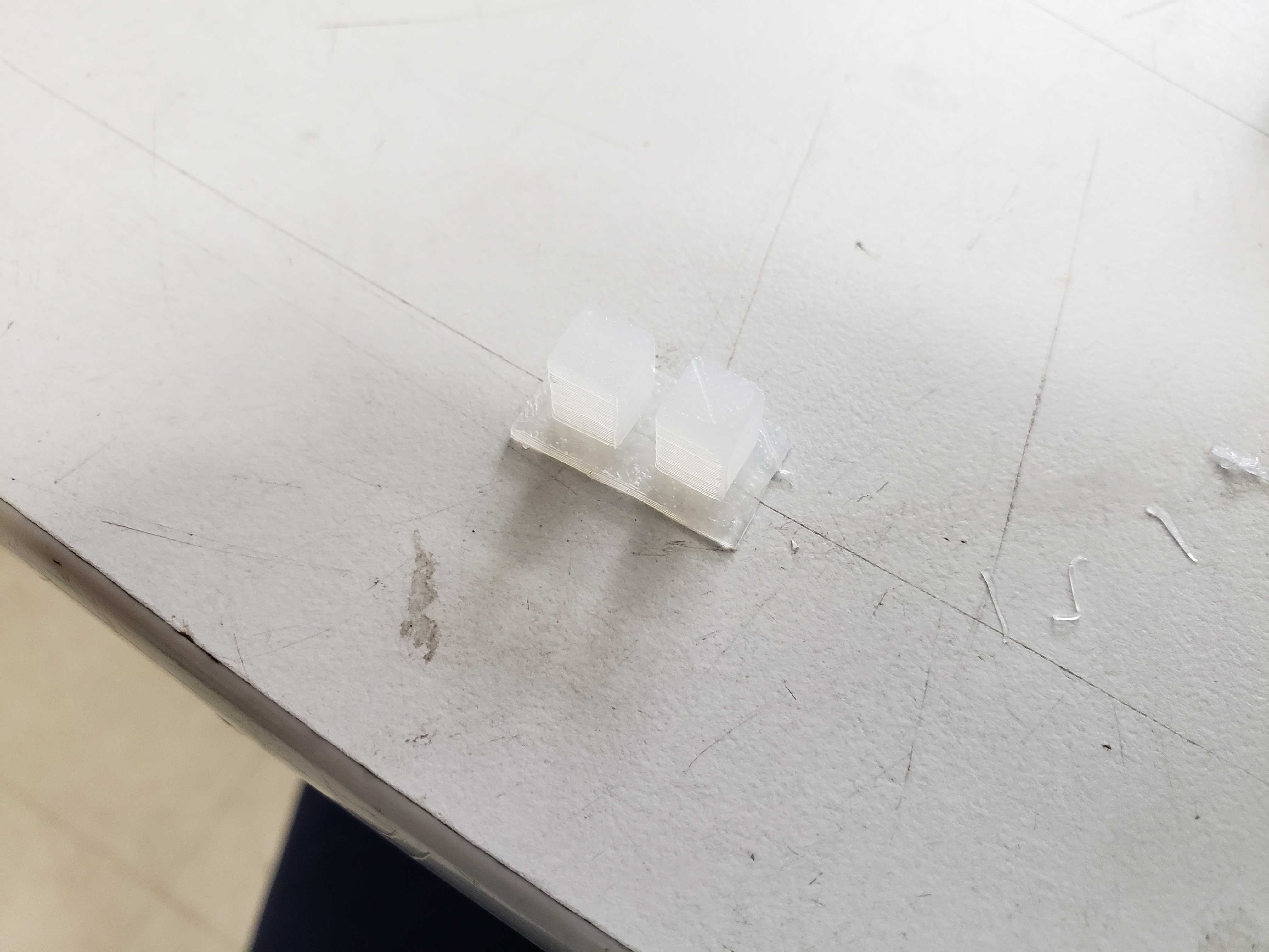
Unfortuntately, the buttons caps were so soft that the buttons would deform rather than push the buttons in. To solve this, I modeled and printed thin spacers of 1mm or 1.5 mm. I printed two versions because the caliper measurement were too uncertain. The 1mm version turned out to be the best version. The spacer was glued to the button caps using multi-purpose glue.
Assembly
The spiral top was finally super-glued onto the top of the wand body.
Oled Displays
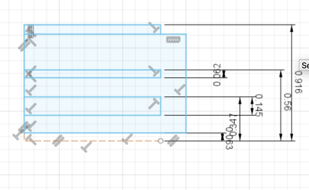
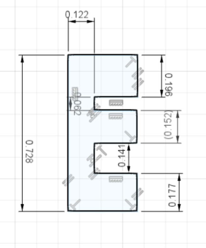
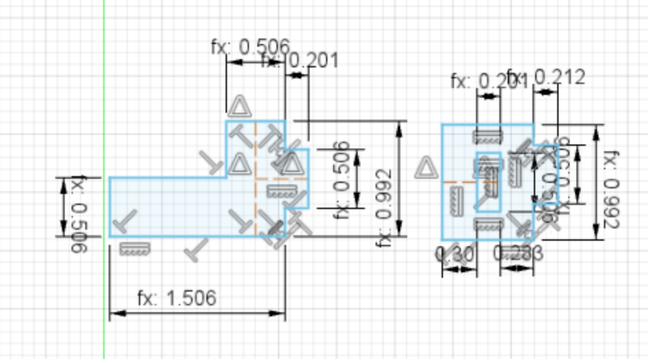
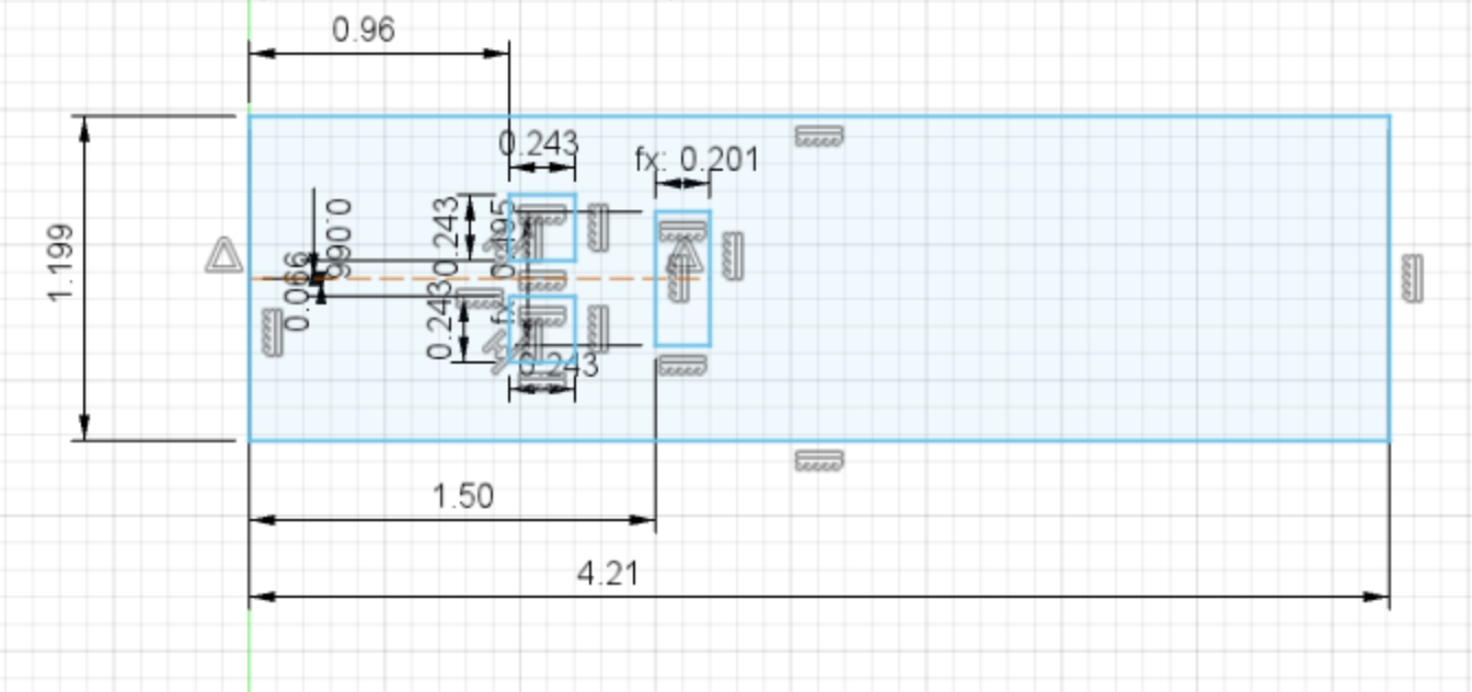
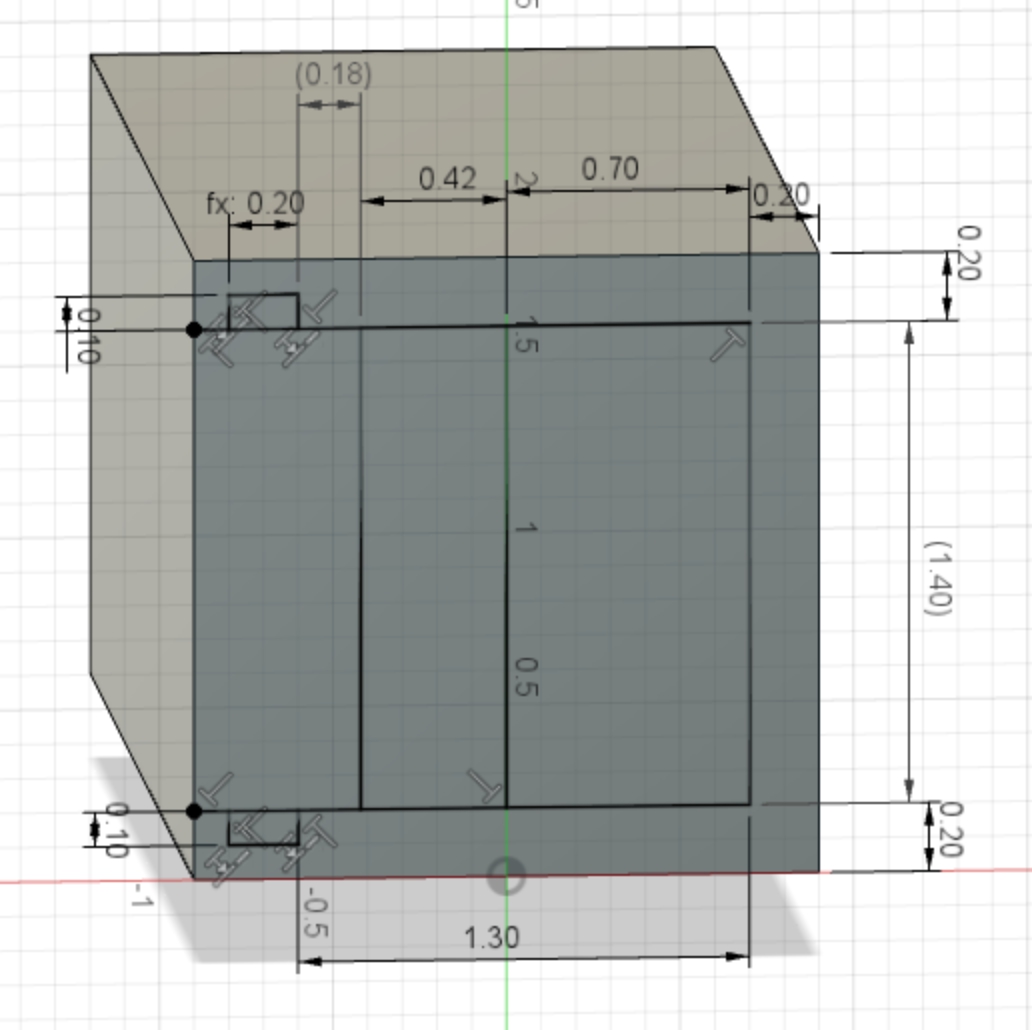
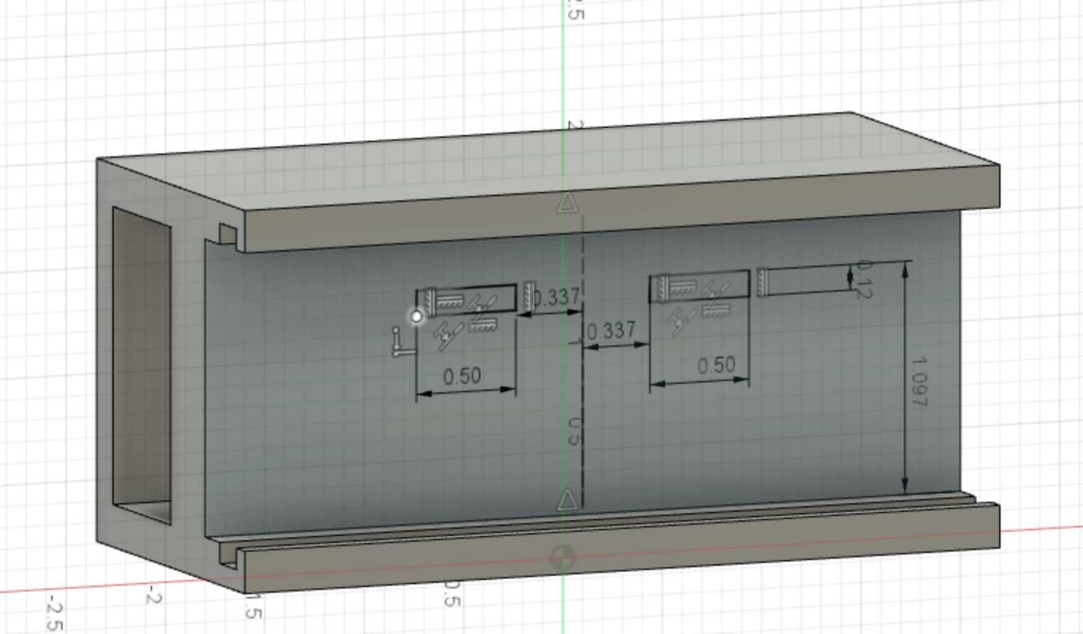
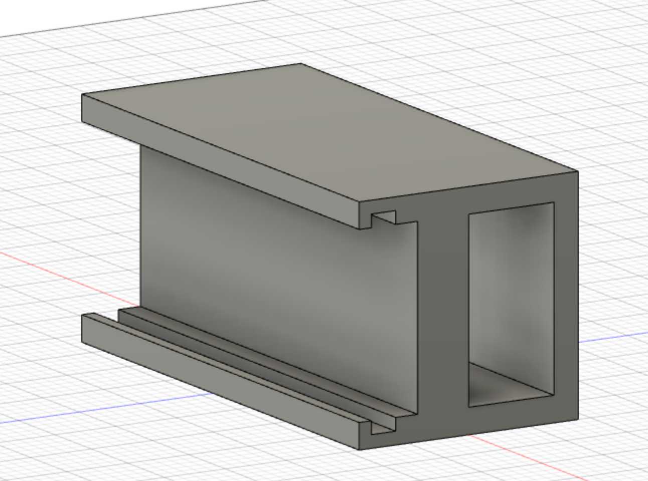
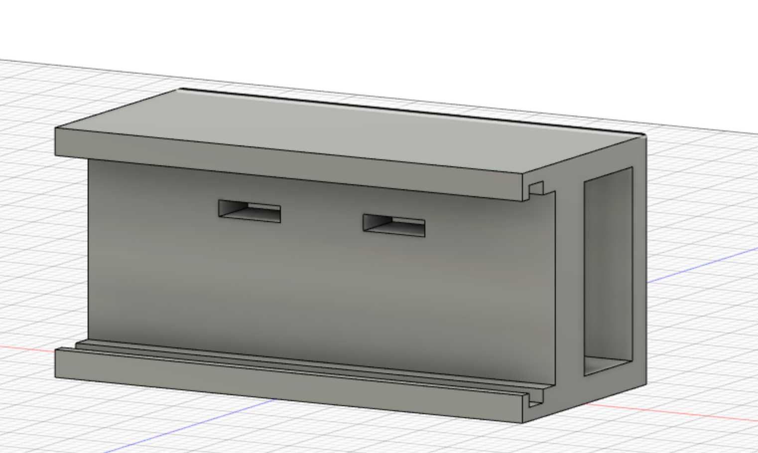
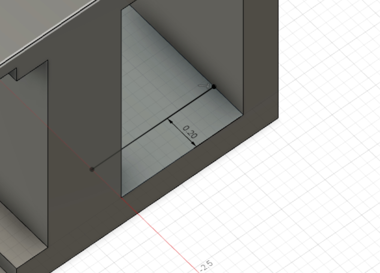
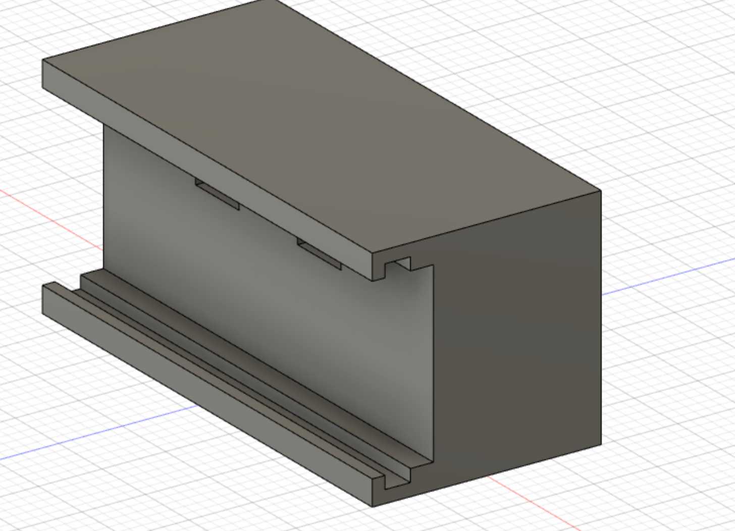
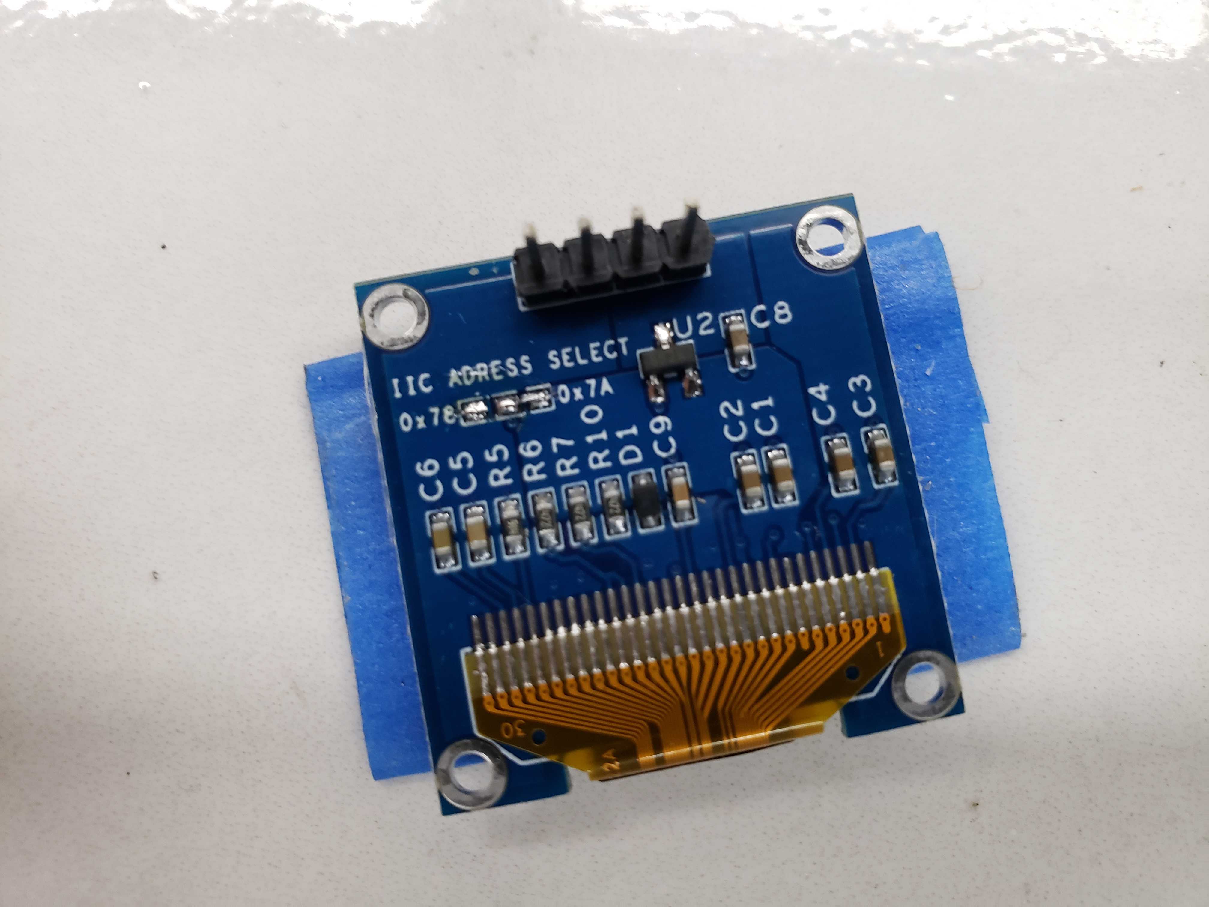
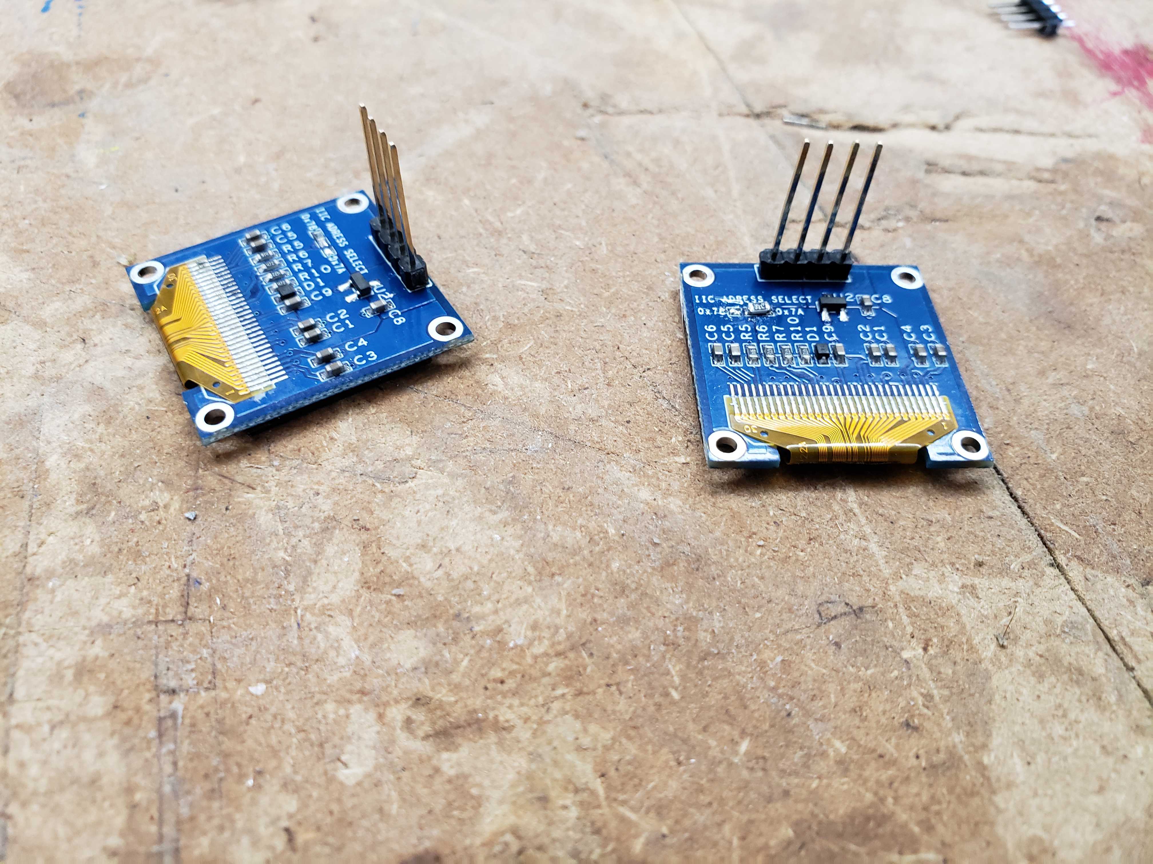
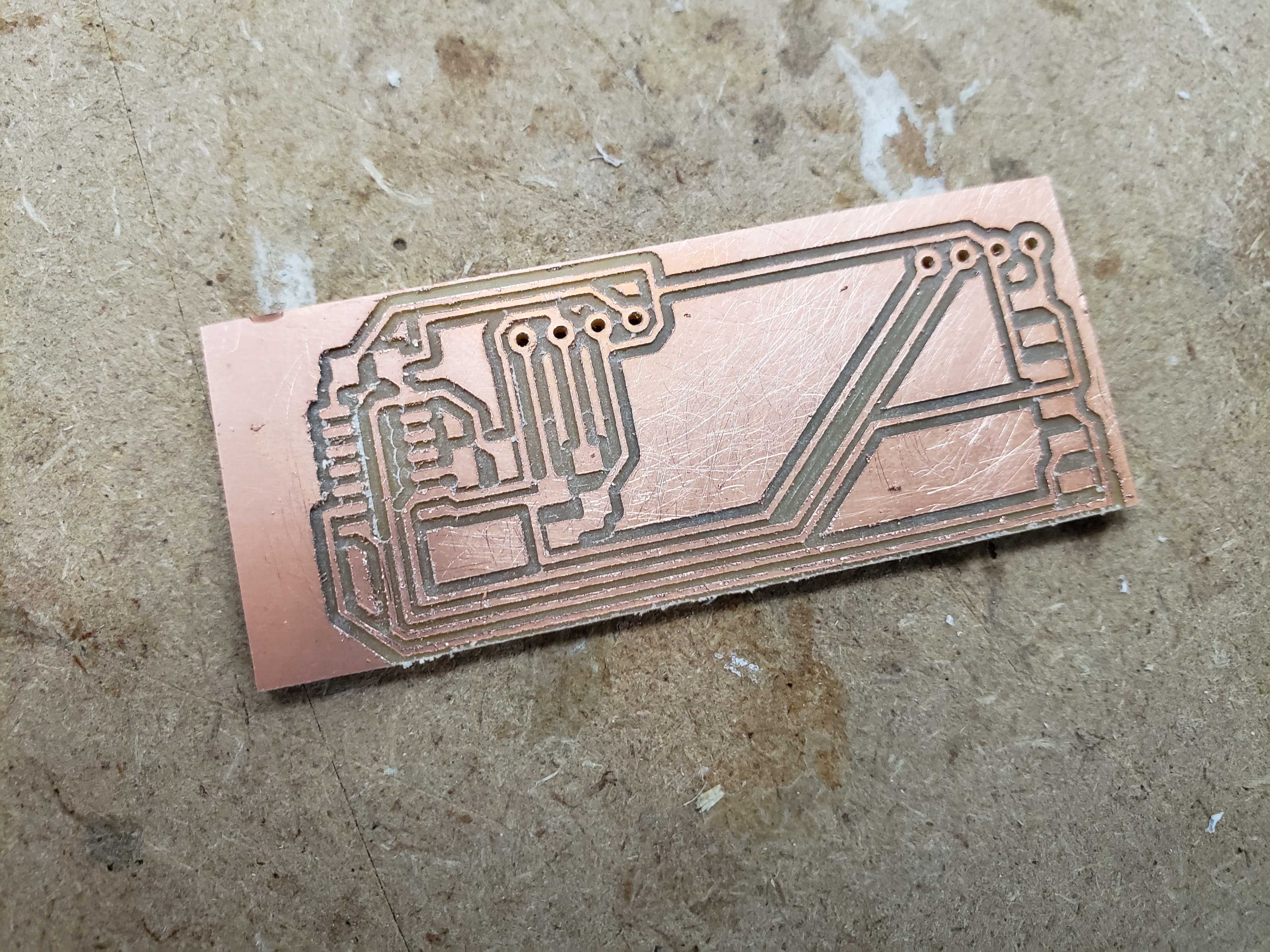
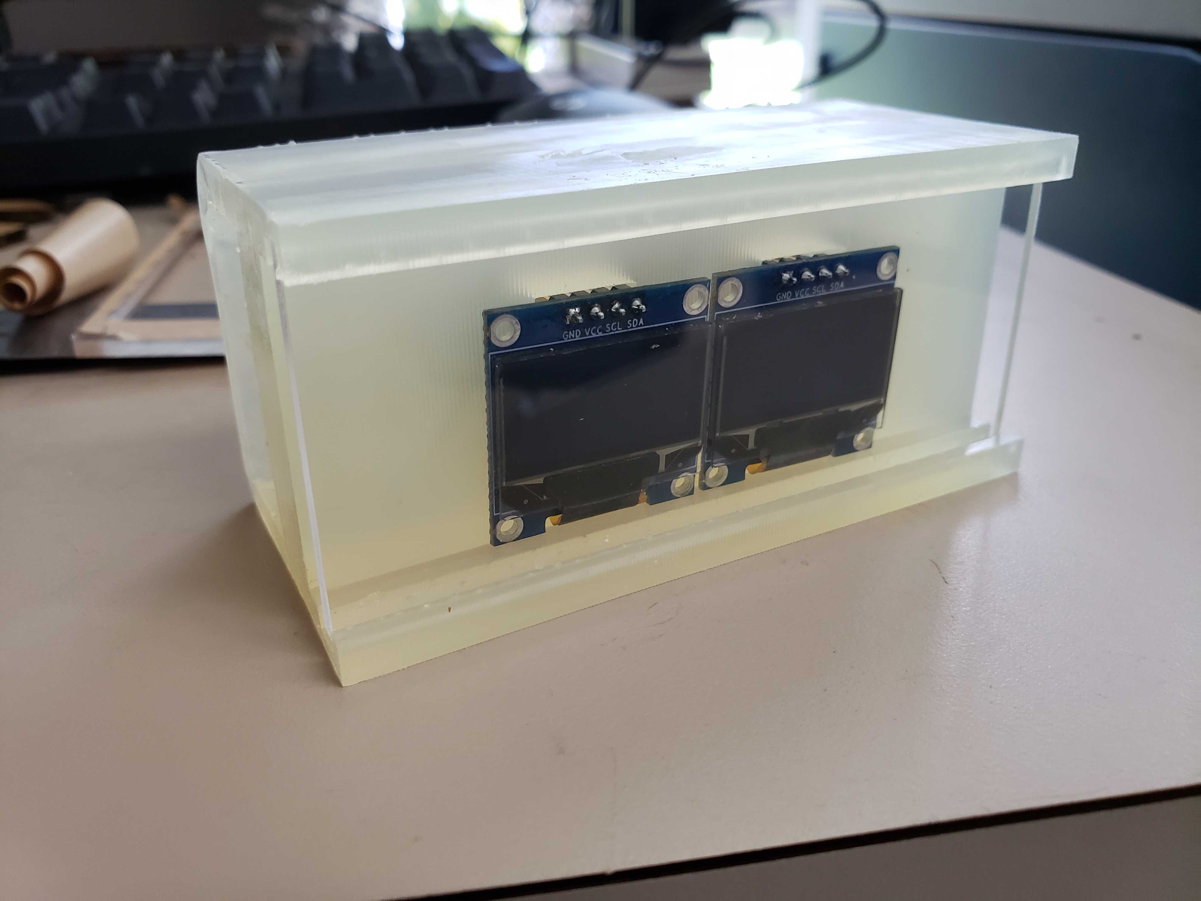
Next, I designed a display for any data that I needed to display, such as rotation. I designed a board that would be able to attach two SSD1306 OLED displays that I had used in my Ouput Week. In addition, I modeled an enclosure to house both displays and the electronics. The two holes in the front of the enclosure is for the displays to connect to the board on the back. The displays will be shielded behind a piece of .20 in. acryllic held by the indents running alonside the lips of the enclosure. Since, I wanted this to be precise I used caliper measurment with the intent of 3D printing the model on the SLA printer instead.
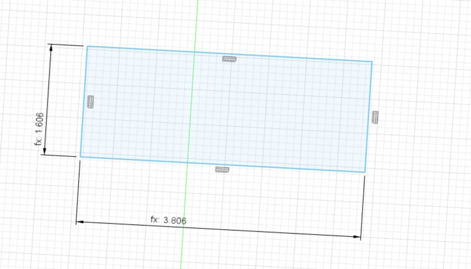
This is the profile for laser cutting the acryllic shields
Before making the boards, I changed one of the OLED screen’s addresses to 7A so that I could modify both screens independently. I also replaced the male headers of both screen’s with longer male headers to ensure that the headers would reach through the enclosure.
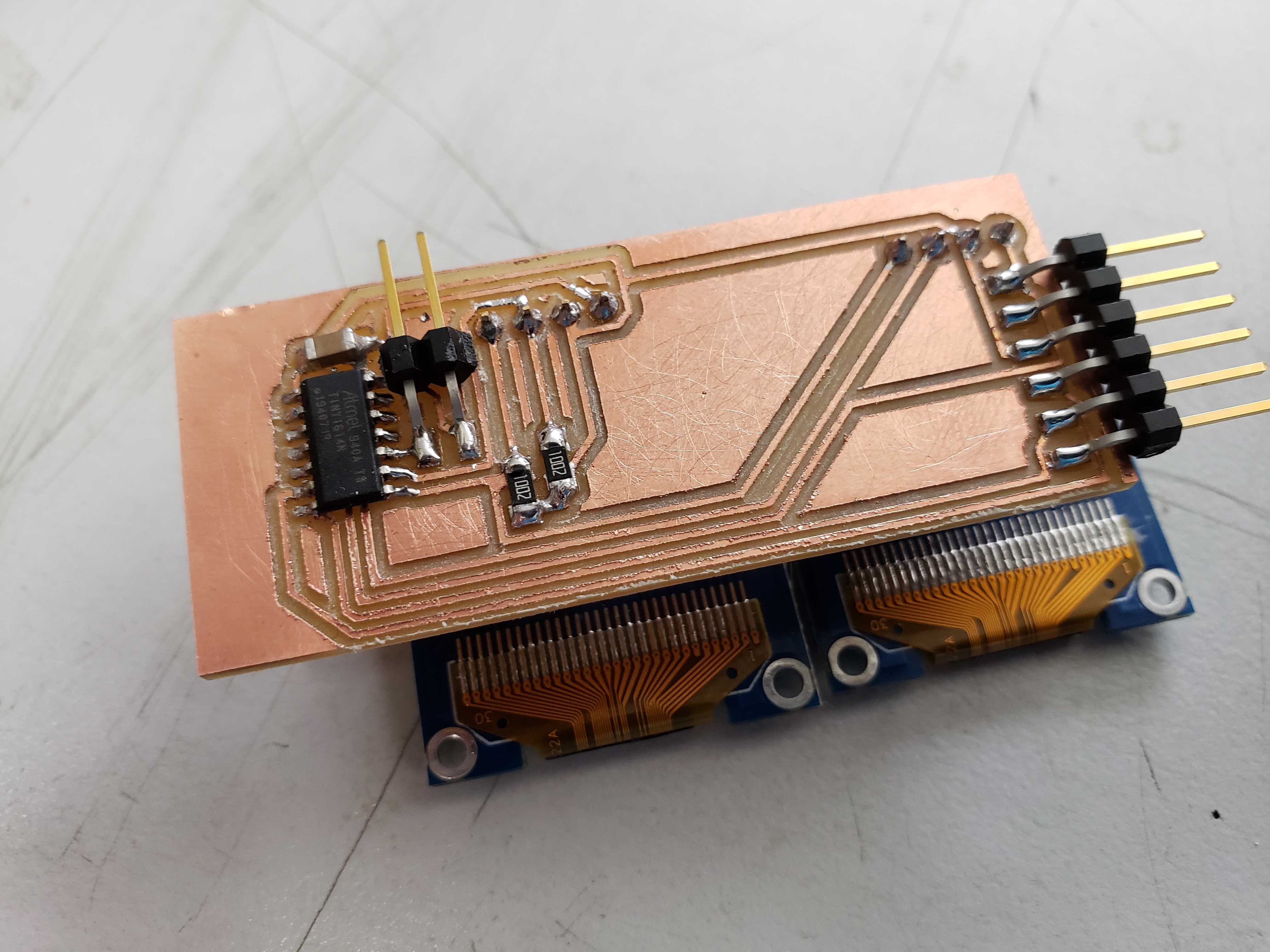
I coded the board to take commands from serial in the format: s{screen #}{row}{column}{text}. Simply, the command tells the board what screen, row, and column a certain piece of text is to be displayed. In addition, the board should be able to take multiple commands by tokenizing the string using the semicolon. Static text, such as identifiers, will be defined in the setup function.
void subString(char* str, char* buff, int index, int len) {
  strncpy(buff, str+index, len);
  buff[len] = '\0';
}
void parseCommand(char* str) {
  //Serial.println("Parsing");

  char screen[3];
  subString(str, screen, 0, 2);
  //Serial.println(commandType);

  char row[2];
  subString(str, row, 2, 1);
  //Serial.println(commandType);

  char column[3];
  subString(str, column, 3, 2);
  //Serial.println(commandType);

  char text[strlen(str)-1];
  subString(str, text, 5, strlen(str)-2);
  //Serial.println(text);


  if (strcmp(screen, "s1") == 0) {
    //Serial.println("Screen 1");
    OLED10x16string(atoi(row),atoi(column), text, slave_addr_1);
  }
  else if (strcmp(screen, "s2") == 0) {
    //Serial.println("Screen 2");
    OLED7x8string(atoi(row),atoi(column), text, slave_addr_2);
  }
}
void setup() {
  //Init TWI
  TWI_init();
  //Initialize both OLEDs
  OLEDinit(slave_addr_1);
  OLEDinit(slave_addr_2);

  OLED10x16string(0,0,"Yaw", slave_addr_1);
  OLED10x16string(2,0,"Pitch", slave_addr_1);
  OLED10x16string(4,0,"Roll", slave_addr_1);
  OLED10x16string(6,0,"Gesture", slave_addr_1);

  //USART0_init();
  Serial.begin(38400);
}
void loop() {
  if (Serial.available()) {
    char buff[60];
    int index = 0;
    while (Serial.available()) {
      if (index < 59)
        buff[index++] = Serial.read();
        _delay_us(1500);
    }
    buff[strcspn(buff, "\n")] = '\0';
    //buff[index] = '\0';

    char* ptr;
    ptr = strtok(buff, ";");
    while (ptr != NULL) {
      parseCommand(ptr);
      ptr = strtok(NULL, ";");
    }
  }
}
To test the code, I wrote a python script that feed commands with random numbers as the text. However, the python script print commands on serial on a delay of about .5 seconds as that delay is the most stable. Going below that delay causes the OLED board to stop updating the OLED screens and freeze up. I found this delay through trial and error.
AI Classification
I used Kaggle in order to leverage the more powerful GPUs and CPUs available. I created a new notebook and I uploaded the datasets that I used. In order to refresh my memory on LSTM networks, I read this article. Kaggle notebooks already come preloaded with most of the popular data science and machine learning packages, such as Keras, Scikit-Learn, Pandas, NumPy, and TensorFlow.
At first, I simply randomized data as the negative set.
random_df = circle_df.copy()
random_df = random_df.sample(frac=1).reset_index(drop=True)
I used a simple LSTM network to decrease complexity and increase performance on my MacBook.
from keras.models import Sequential
from keras.layers import Dense
from keras.layers import LSTM
from keras.layers import Input
from keras.metrics import AUC

# create and fit the LSTM network
model = Sequential()
model.add(LSTM(50, input_shape=(10, 3)))
model.add(Dense(1, activation='sigmoid'))
model.compile(loss='binary_crossentropy', optimizer='adam', metrics=[AUC(), 'accuracy'])
print(model.summary())
Unfortunately, the LSTM was unable to differentiate random motion from the circular motion.
I decided to make the random data more “realistic” by sampling from the normal distribution fit on the circular motion.
from scipy.stats import norm
yaw_dist = norm.fit(circle_df["yaw"])
pitch_dist = norm.fit(circle_df["pitch"])
roll_dist = norm.fit(circle_df["roll"])

def get_random_df(size):
    X = np.zeros(((int)(circle_df.shape[0]/10), 10, 3))
    print(X.shape)
    for i in range(0, circle_df.shape[0], 10):
        for j in range(i, i+10):
            X[int(j/10)][j-i][0] = norm.rvs(yaw_dist[0], yaw_dist[1], random_state=seed+j+i)
            X[int(j/10)][j-i][1] = norm.rvs(pitch_dist[0], pitch_dist[1], random_state=seed+j+i)
            X[int(j/10)][j-i][2] = norm.rvs(roll_dist[0], roll_dist[1], random_state=seed+j+i)

    return X

random_X = get_random_df()
Furthermore, I used 5-fold cross validation as a better means of training the NN.
from sklearn.model_selection import KFold
kfold = KFold(5, shuffle=True, random_state=seed)
for train, validation in kfold.split(X_train, y_train):
    model.fit(X_train[train], y_train[train], validation_data=(X_train[validation], y_train[validation]), epochs=1, batch_size=64)
The results did not differ from before. I decided that more data was required to fully train the network. I gathered 3 more datasets: pitch, quick, and still. Pitch is where I rapidly change the pitch of the wand. Quick is where I subject the wand to rapid, random motion. Still is where I leave the wand still.
To create even more data for the negative set, I masked some columns of the circle dataframe with samples from a normal distribution fitted on the circle dataframe.
temp1 = circle_df.copy()
temp2 = circle_df.copy()

yaw_dist = norm.fit(circle_df["yaw"])
pitch_dist = norm.fit(circle_df["pitch"])

temp1["yaw"] = norm.rvs(yaw_dist[0], yaw_dist[1], size=circle_df.shape[0], random_state=seed)
temp2["pitch"] = norm.rvs(pitch_dist[0], pitch_dist[1], size=circle_df.shape[0], random_state=seed)
mask_df = temp1.append(temp2).reset_index(drop=True)
I dropped the first rows of data due to the rx buffer being full of data when I collected the datasets. In addition, I realized that the absolute rotation might cause overfitting and I used the differences in angles between time frames in stead.
circle_df = circle_df.diff().fillna(0).drop(range(0, 90))
still_df = still_df.diff().fillna(0).drop(range(0, 90))
quick_df = quick_df.diff().fillna(0).drop(range(0, 90))
pitch_df = pitch_df.diff().fillna(0).drop(range(0, 90))
This drastically increased the performance of the LSTM NN. THe NN filters out nearly all of the miscellenous movements.
Project In Action
Update
Neil suggested that I make a bitmap display when the gesture is detected so I set to work implementing the displaying code for the bitmap. I didn’t want to use any third-party libraries due to worries about the size of the libraries and the potential incompatiblities with the libraries and hardware I2C. I found a guide that used the exclusively the Wire library that I could easily adapt into hardware I2C. However, I needed to make several modifiations to get this funcitonality to work.
First, I needed to add an if-else block inside the OLEDinit() function because the guide uses a different memory address mode.
if (bitmap) OLEDcommands(0x20,0x00, slave_address);
else OLEDcommands(0x20,0x02, slave_address);
Next, I adapted the functions to make use of the hardware I2C functions.
void OLED_draw_bmp(unsigned char* bitmap, unsigned char slave_address) {
  for(int i=0; i<1024; i++){
    TWI_start(slave_address);
    TWI_write(0x40);
    for(unsigned char x=0; x<16; x++){
       TWI_write(pgm_read_byte(&bitmap[i])); //Transmit data to be displayed
       i++;
    }
    i--;
    TWI_stop(); //End communication with slave
  }
}
Now, I scaled my image into the resolution of the OLED screen (128 x 64). To generate the byte array for the scaled image, I used this site. Since one screen is now unvailable for displaying information, I rearranged the information to fit onto one screen and modified the python code accordingly.
Here is the updated project:
Files
Primary files: Files
Update files: Files