5. Electronics production
Group Assignment:
- Test the design rules for your 3D printer(s)
Individual Assignment:
- make an in-circuit programmer by milling and stuffing the PCB,
- test it, then optionally try other PCB processes
PCB Production
G-Code
To create a programmer, we followed this guide.
The PNG files for the traces and outlines were provided by the guide. However, the website did not provide any methods to generate g-code files from the PNG files.
However, we looked at past alumni’s Fab Academy websites and found that Ms. Fabian used Fab Mods to generate her gcode files.
In order to access the tool that generate gcode from PNG, you must right click and navigate to program > open server program > mill 2D PNG.
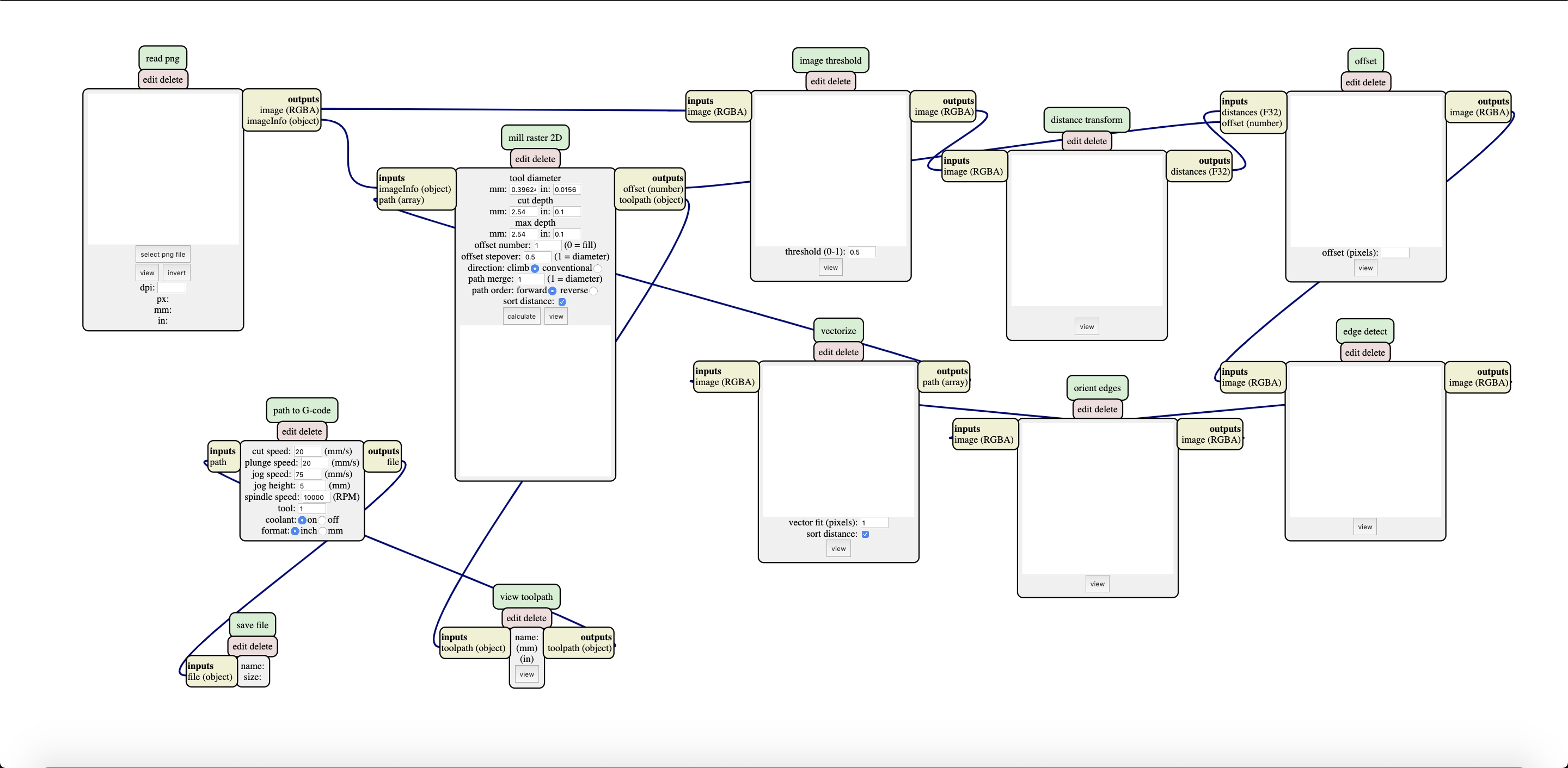
For each PNG we followed the following process:
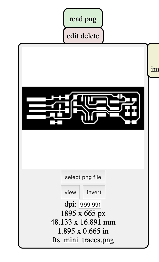
First, open the PNG file in the “read PNG” box
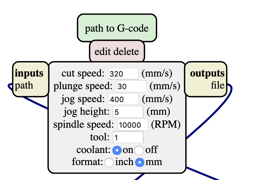
Second, change the “path to g-code” box settings according to the recommended settings for the required bit size.
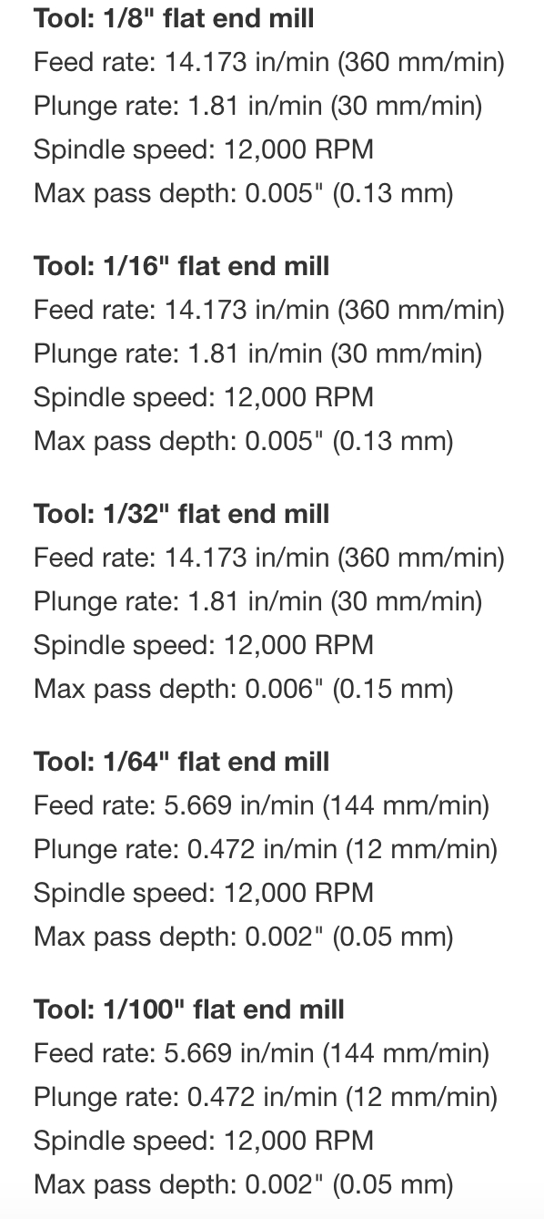
Third, change the “mill raster 2D” box settings according to the recommended settings for the required bit size. - Tool diameter reflects the bit size. - The max depth of traces is equal to cut depth, but the max depth of the outline is equal to FR-1 thickness.
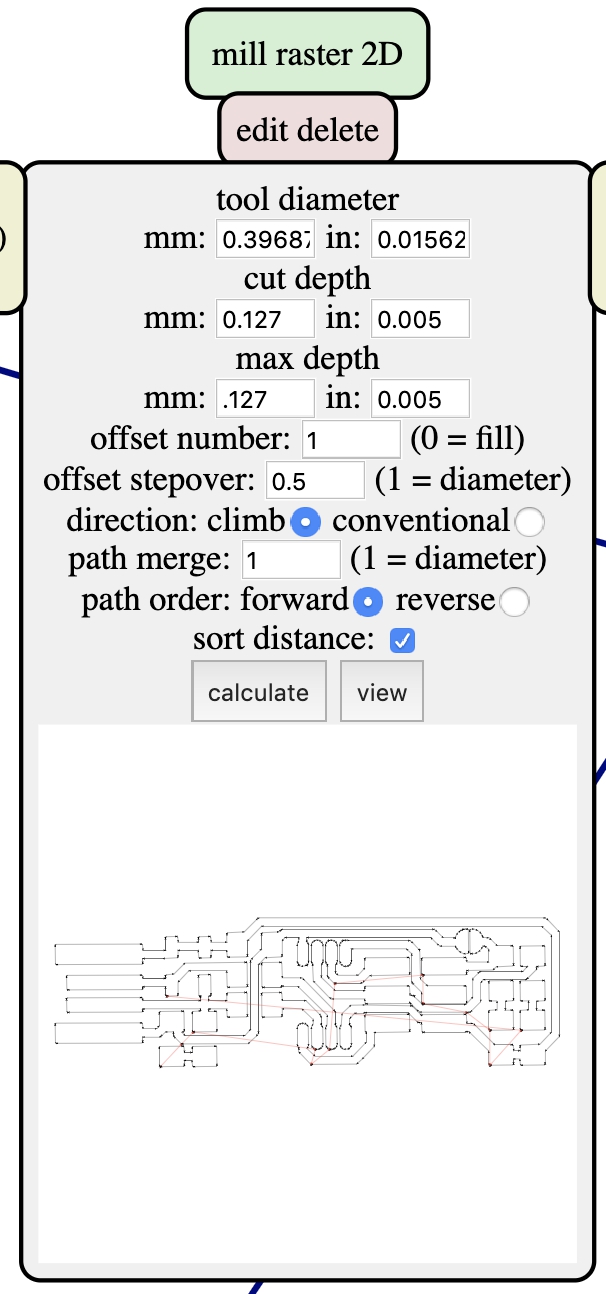
Fourth, click calculate and save the g-code file.
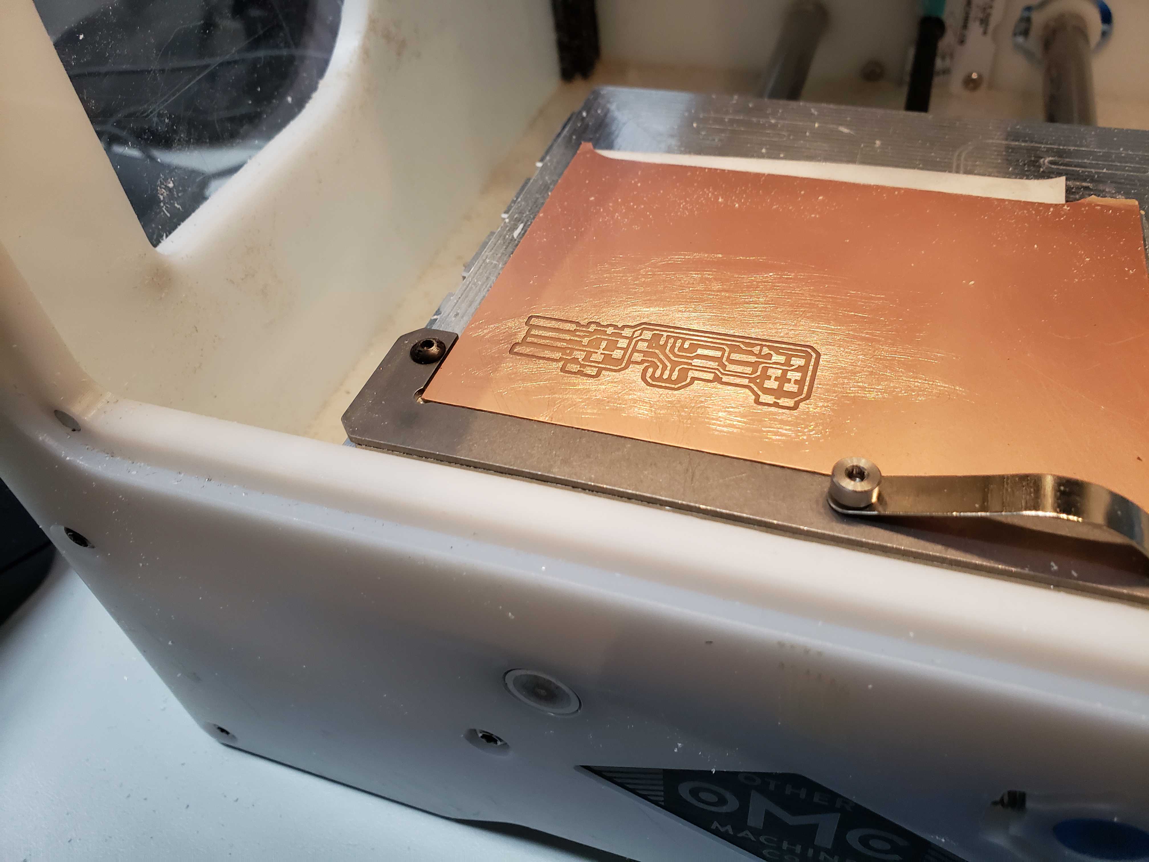
Milling
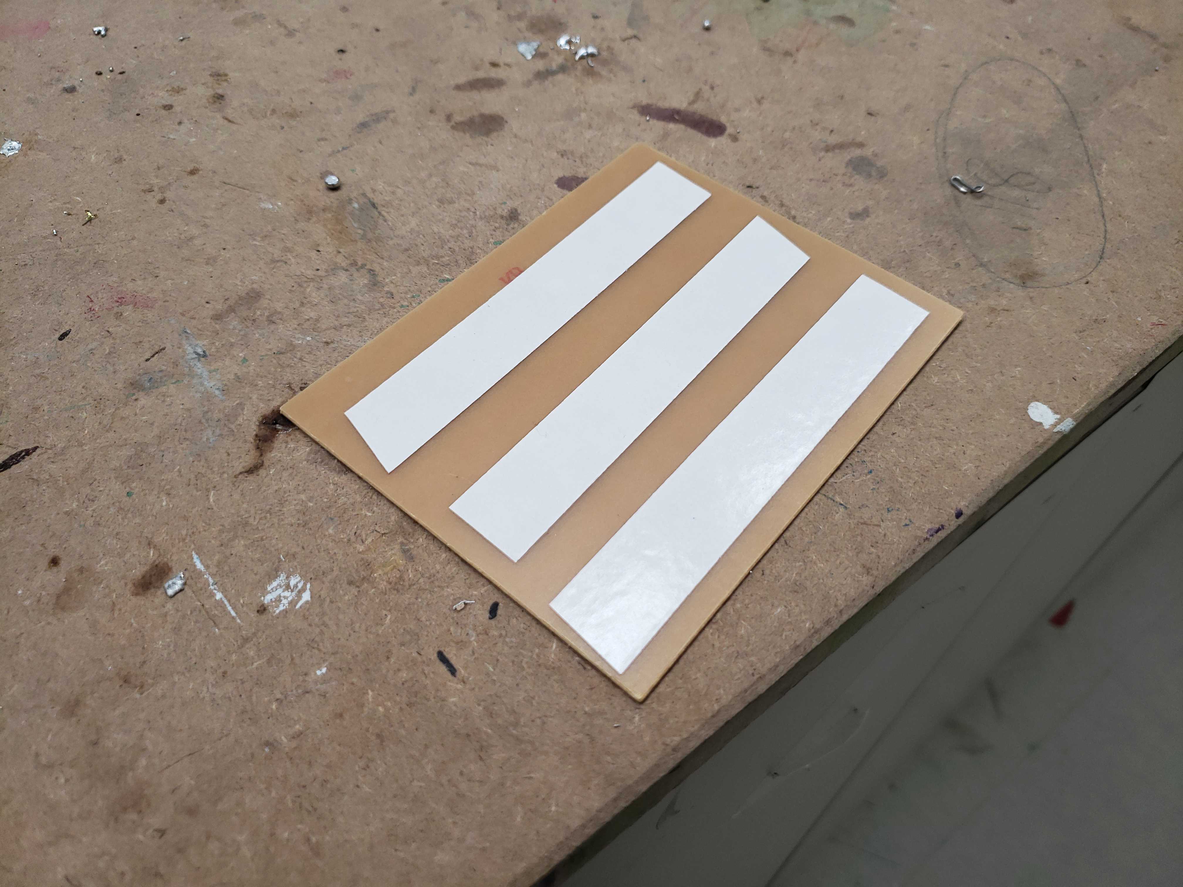
The material used to fabricate the boards was single sided FR-1. We used Neato double-sided tape to keep the FR-1 attached to the base plate of an Othermill Pro.
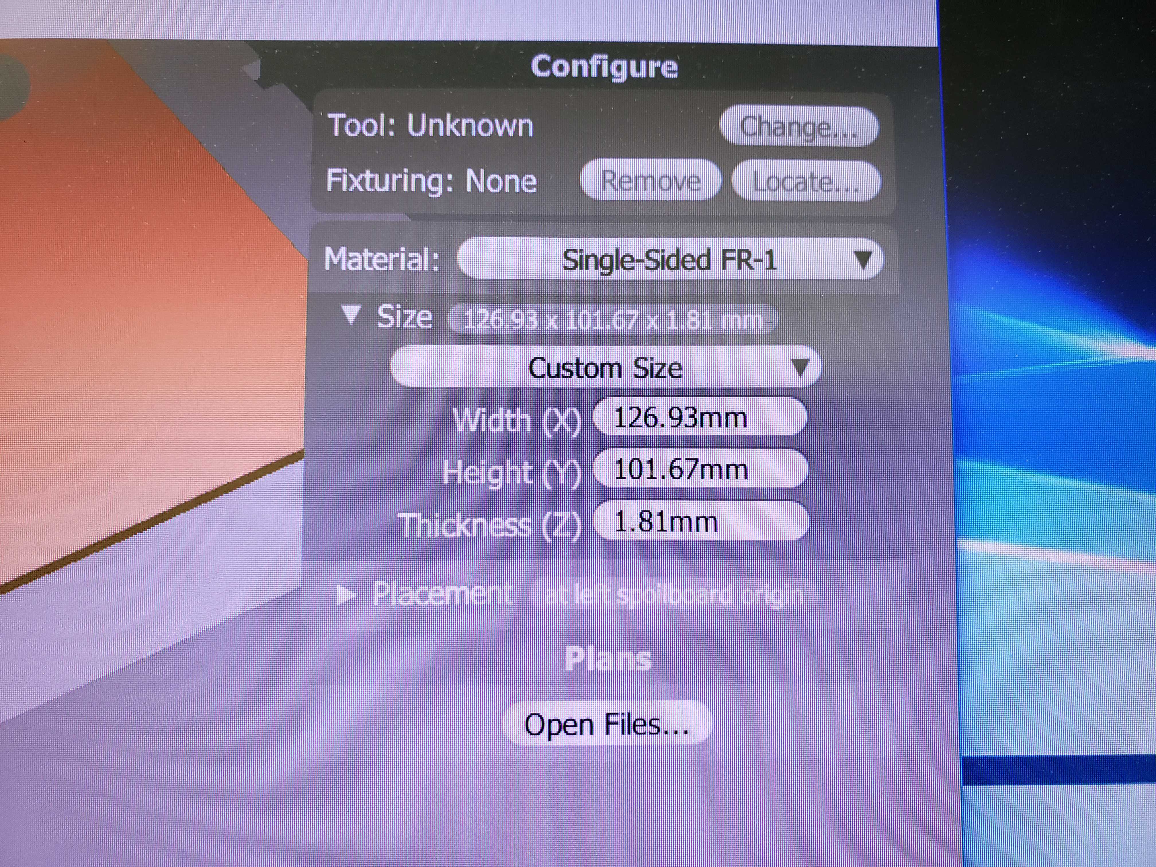
Then, we measured the FR-1 piece with calipers and entered the measurements into the Bantam Tools software.
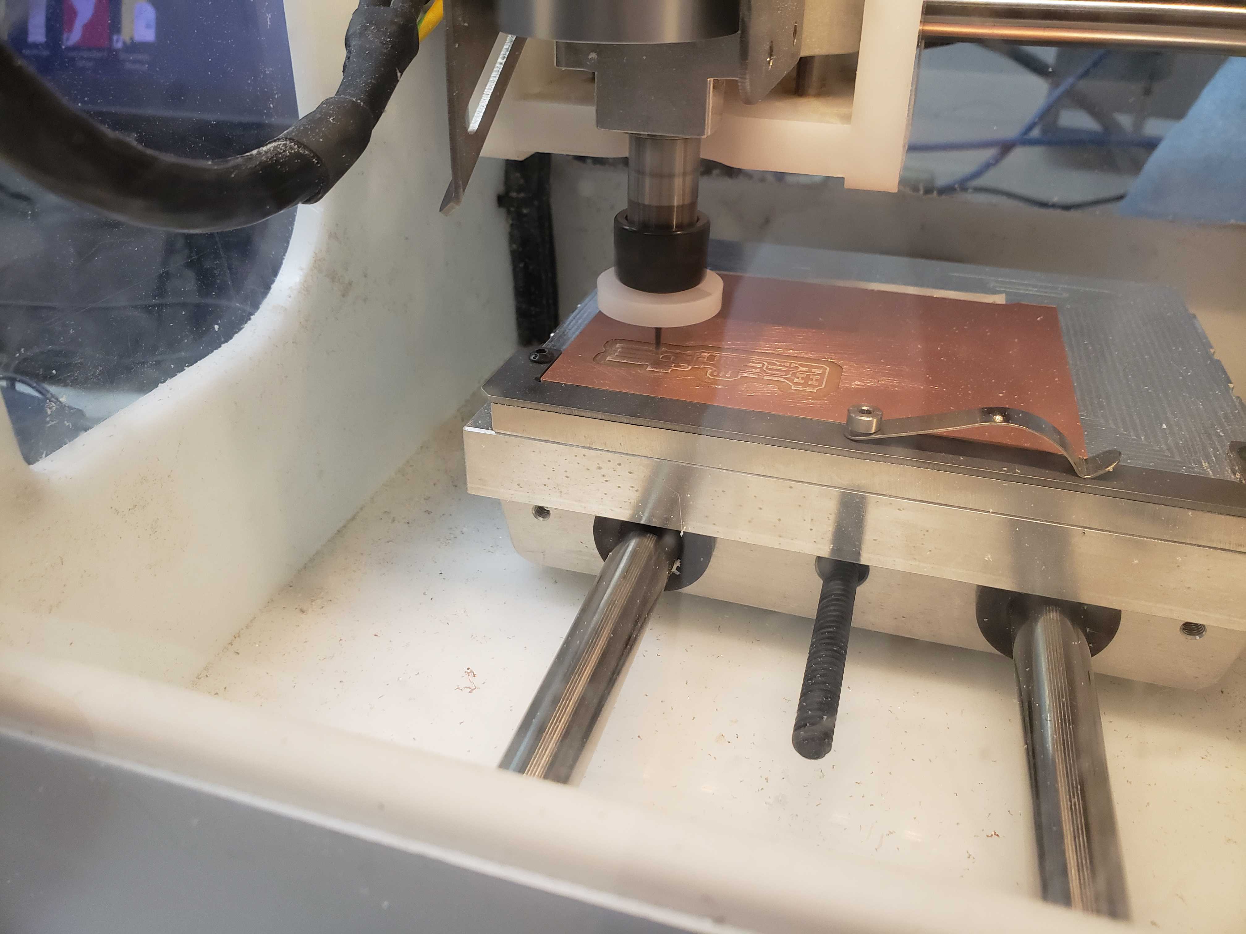
We also installed a 1/64in. bit into the milling machine and changed the bit in software. The BitBreaker tool was used to determine material depth through electrical probing.
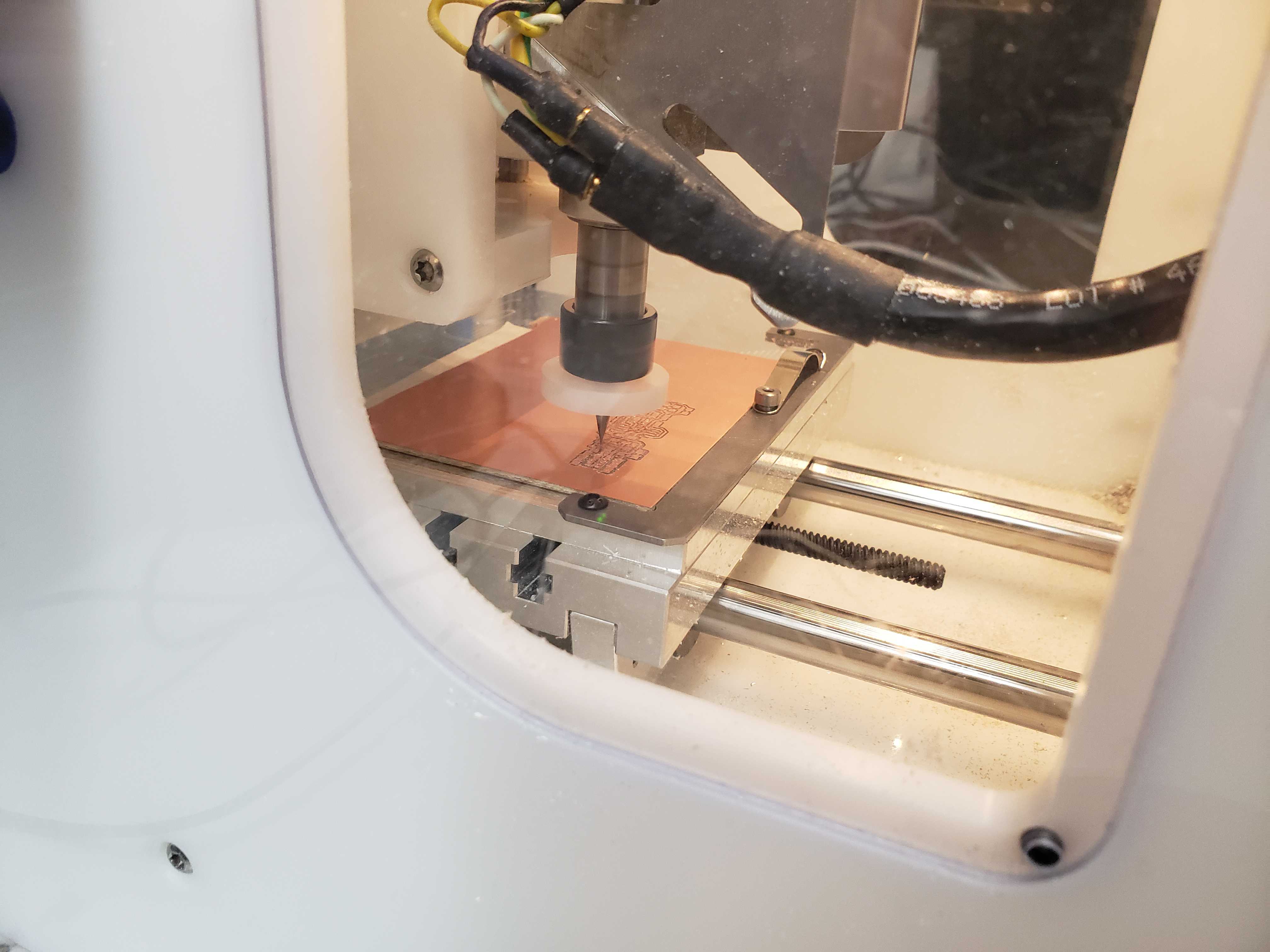
Next, we imported the two g-code files in order to mill out each PCB. We made sure the offsets for both files were the same with a 4mm offset on the X and Y axis. One file provided the instruction to mill the PCB traces using the 1/64th in. flat end mill bit.
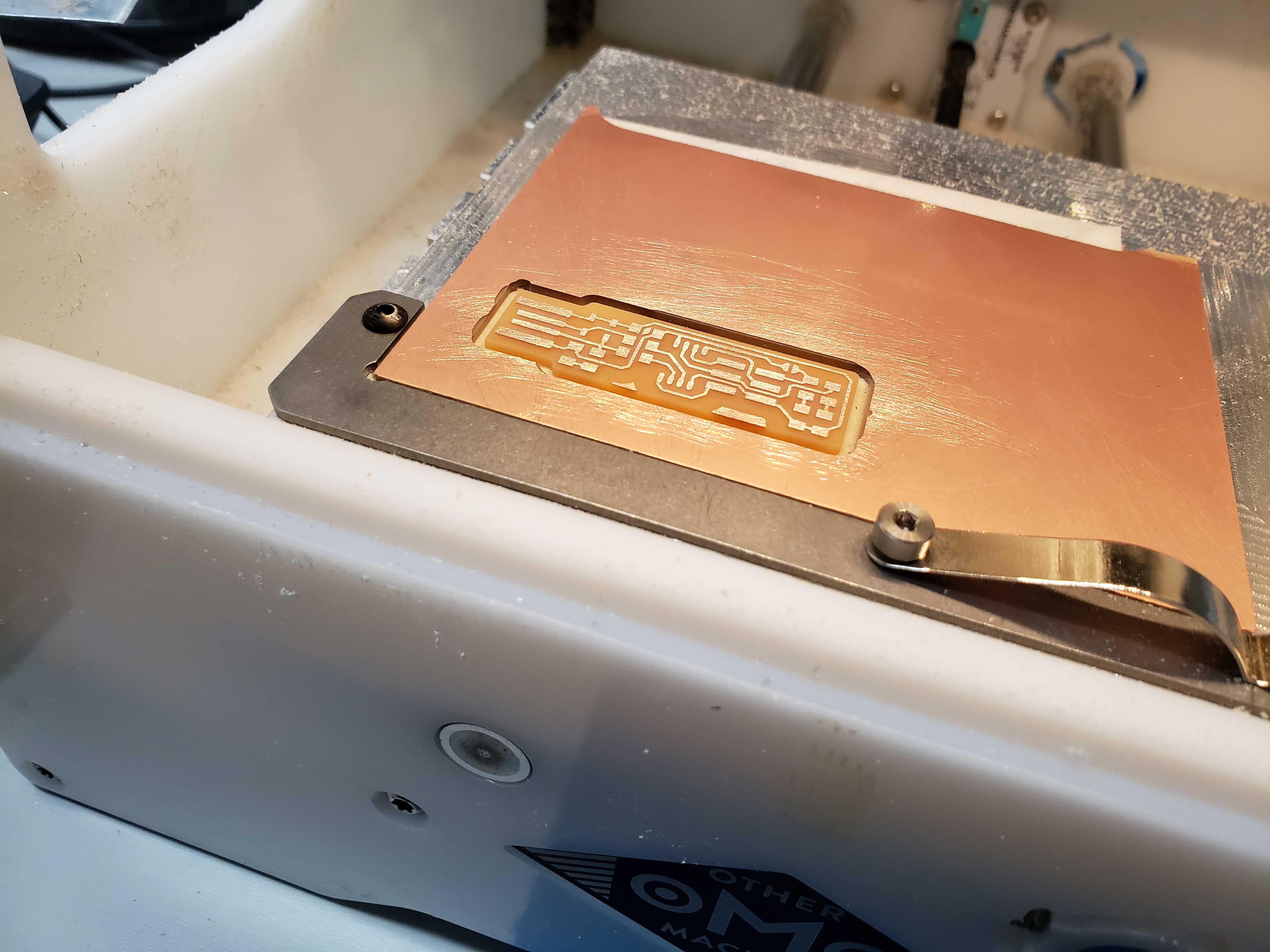
After the PCB traces were milled out we sanded down the top of the FR-1 to remove any burrs. Then, we changed the bit to a 1/16in. flat end mill bet.
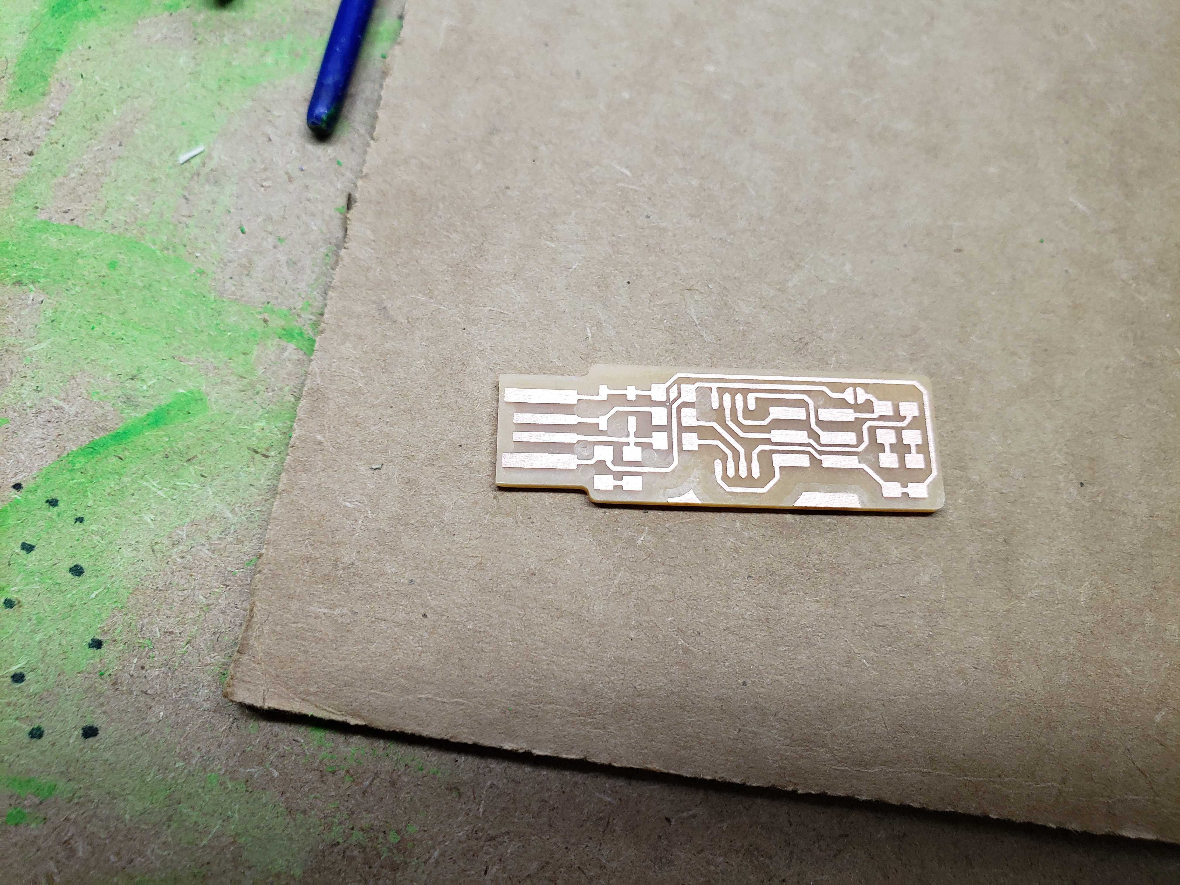
The other file cut out the PCB from the rest of the material using the 1/16th in. flat end mill bit.
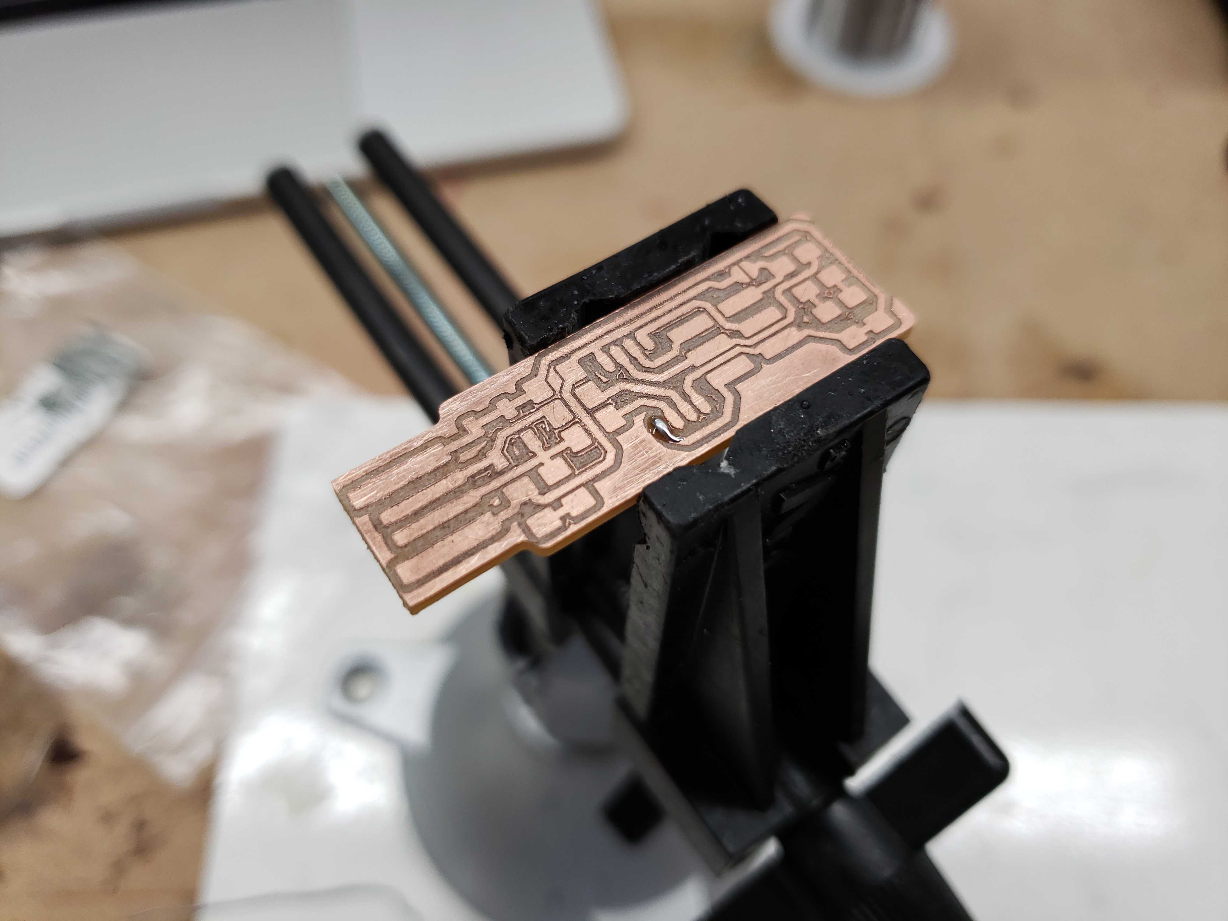
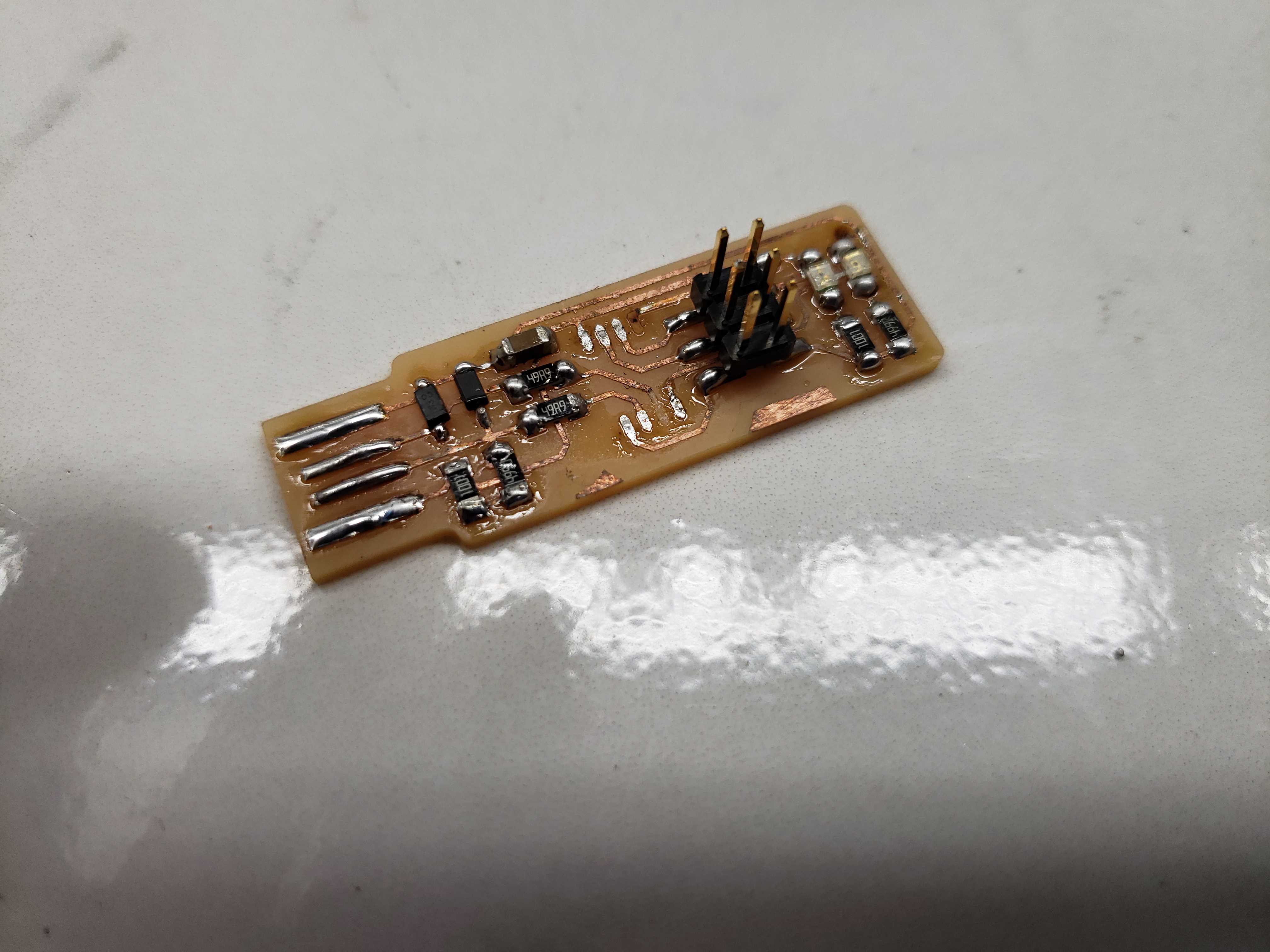
Here is what my first board looked like:
Surface-Mount Soldering
The Basics
We also were instructed before Fab Academy on an effective technique for surface mount soldering.
For chip components that require many contacts, we would first apply solder to one corner of the contacts.
Then, we would use tweezers to hold the chip in place while heating up the solder to allow the chip pins to align with the contacts.
Finally, we would solder the opposite corner of the contacts to secure the chip. It becomes a trivial task to solder the rest of the contacts.
For components with two contacts, such as resistors, diodes, and LEDS, we would first apply solder to one contact.
Then, we would use tweezers to hold the component in place while heating up the solder to allow the component to align with the contacts.
Finally, we would solder the other side.
The required parts and polarities are given on the guide.
Pain
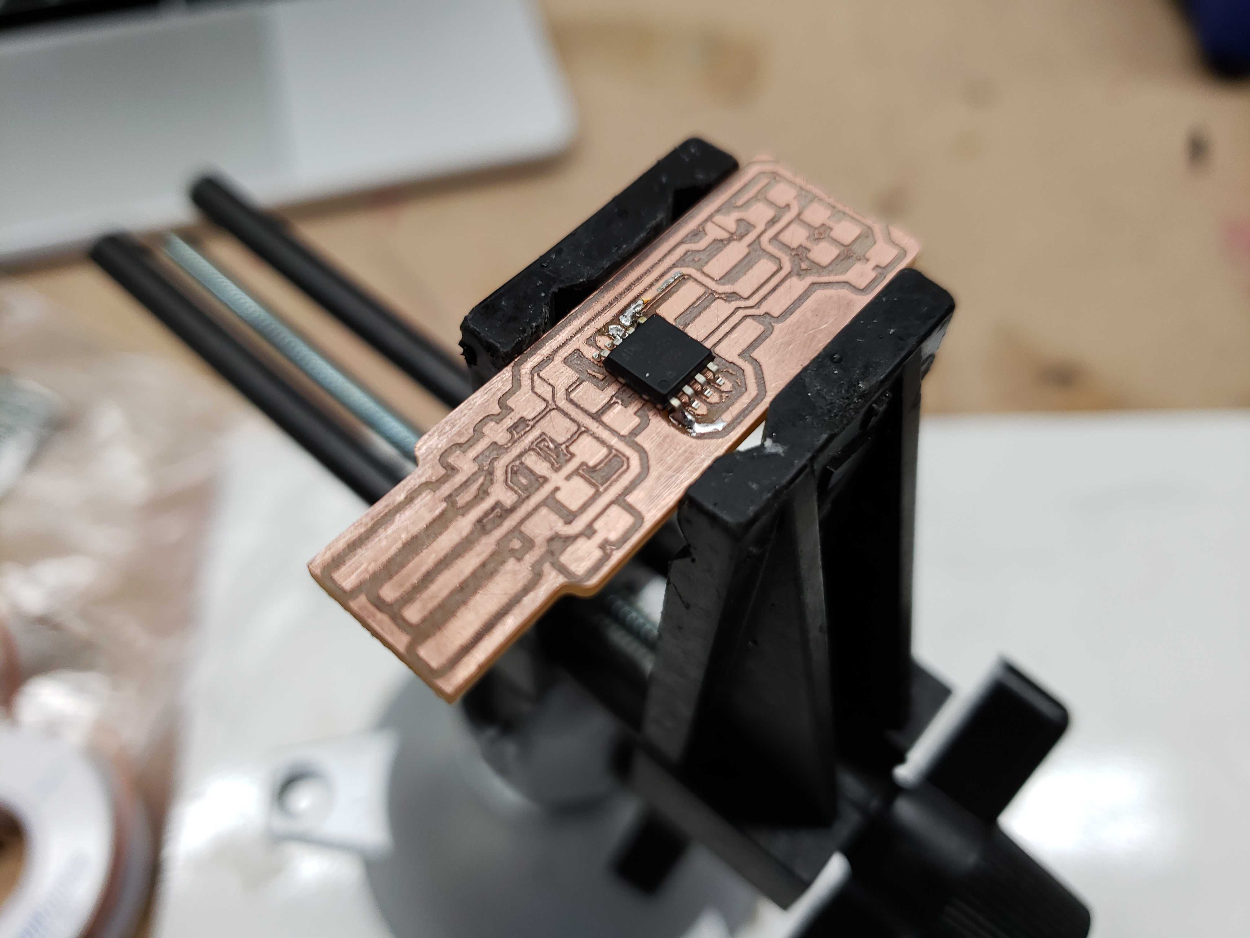
After finishing the first board, I realized that the chip was oriented the wrong position. The dot on the chip was supposed to be facing the USB contacts. I tried to desolder the chip pins, but I ended up ripping the traces off of the board.
I remilled another board, however, Mr. Dubick suggested that we use the engraving bit to mill the traces instead. Unfortunately, the engraving bit did a poor job of removing copper material and left behind many copper bits that could potentially cause a solder bridge. Pressed for time, I decided to solder the board anyway and tried to scrape off the most concerning bits of copper.
I ended up discarding this board as well because the board was unable to be consistently powered and unable to be recognized as a programmer on a computer.
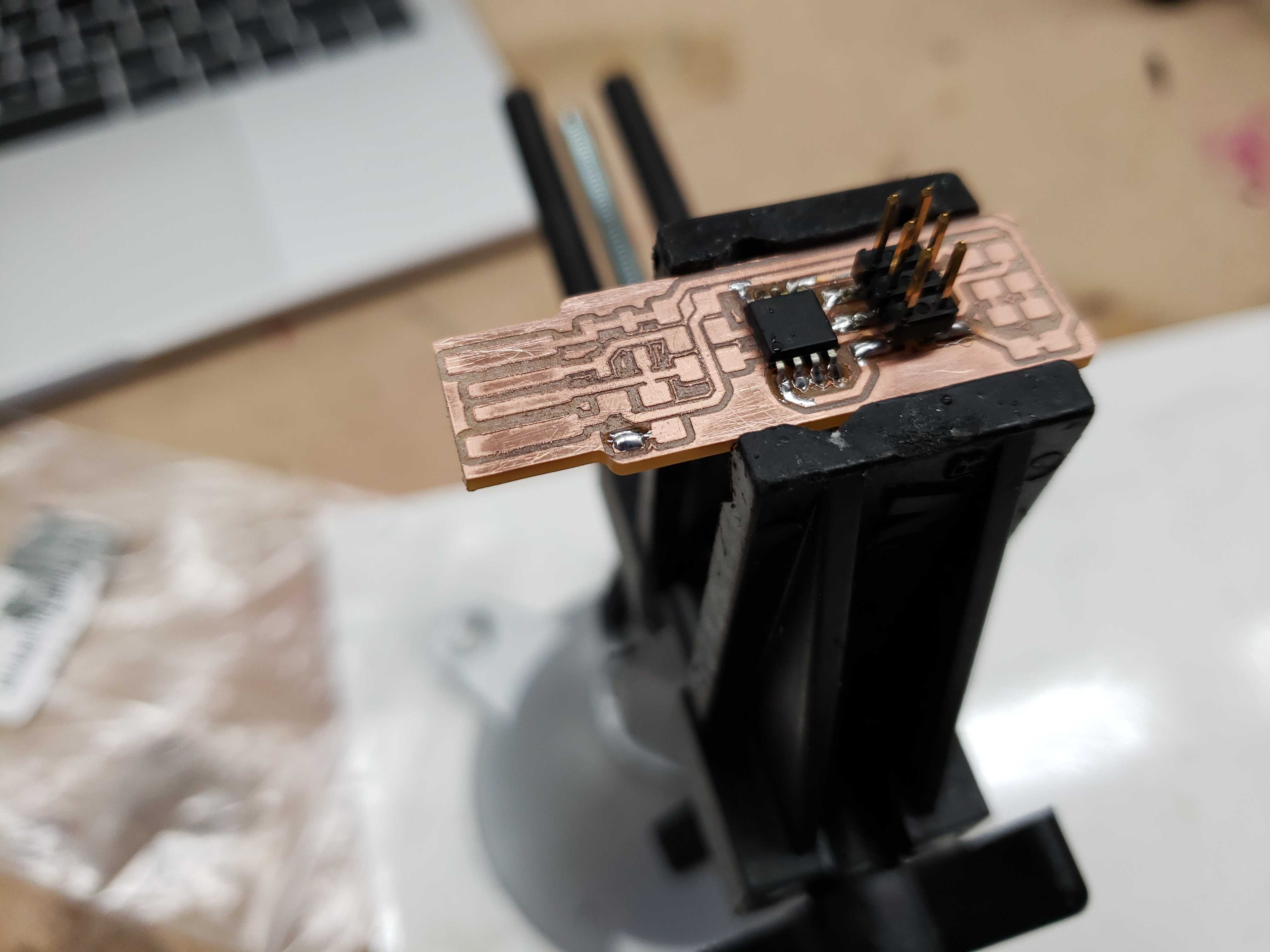
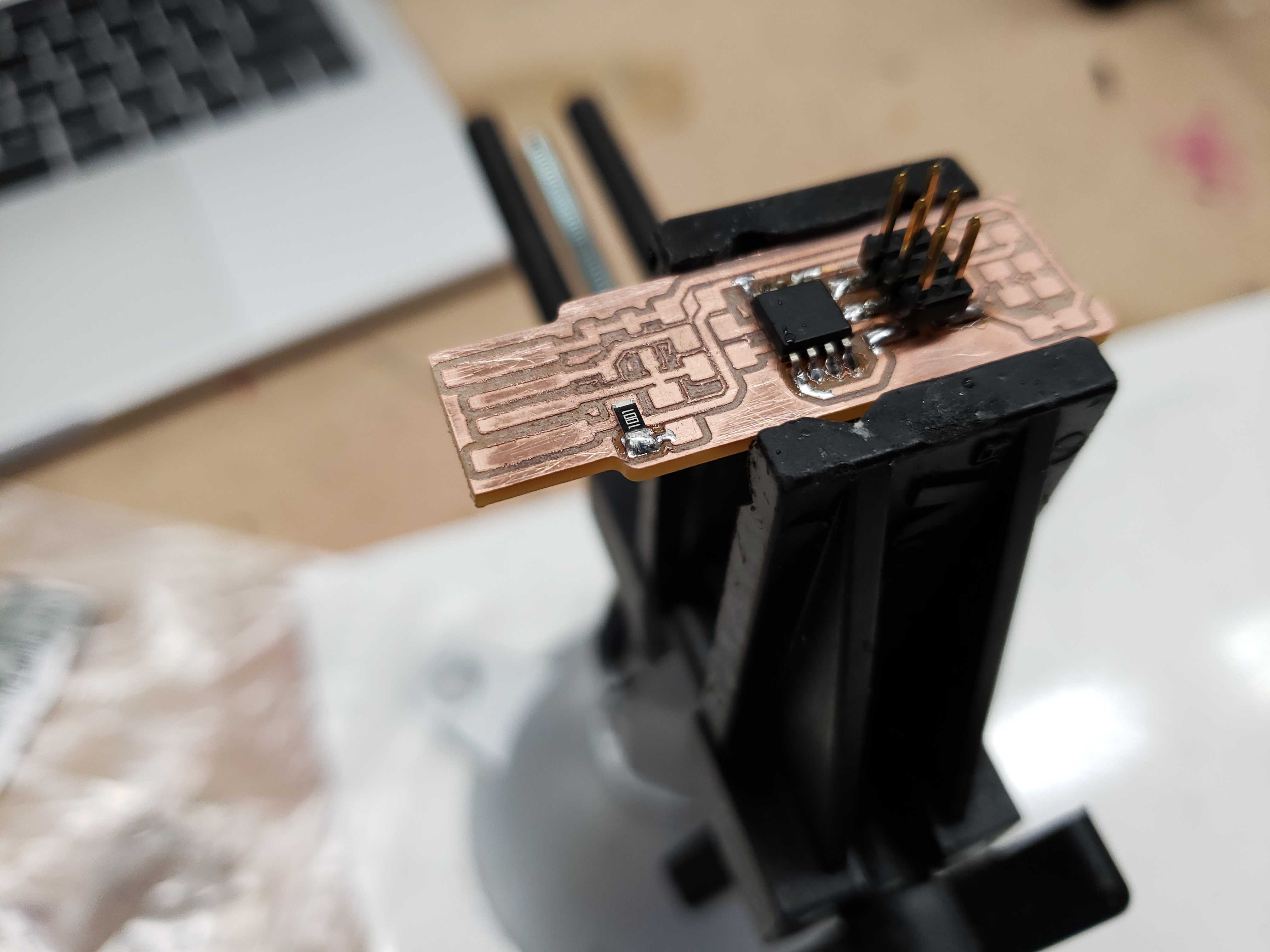
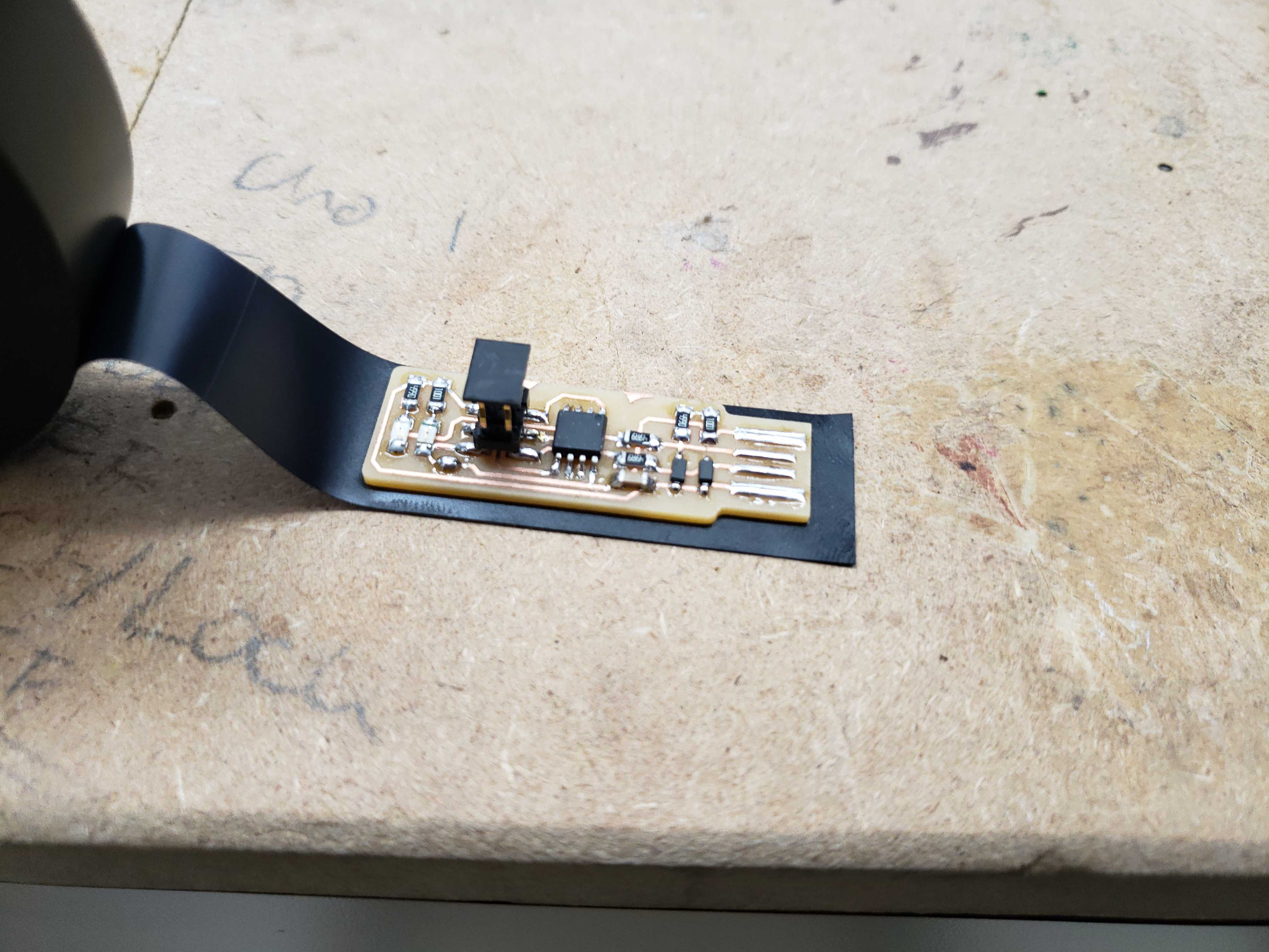
Once again, I remilled a third board using the trusty 1/64th bit again. Thebm I soldered on all the components with intense care to get the right polarity and orientation for all components.
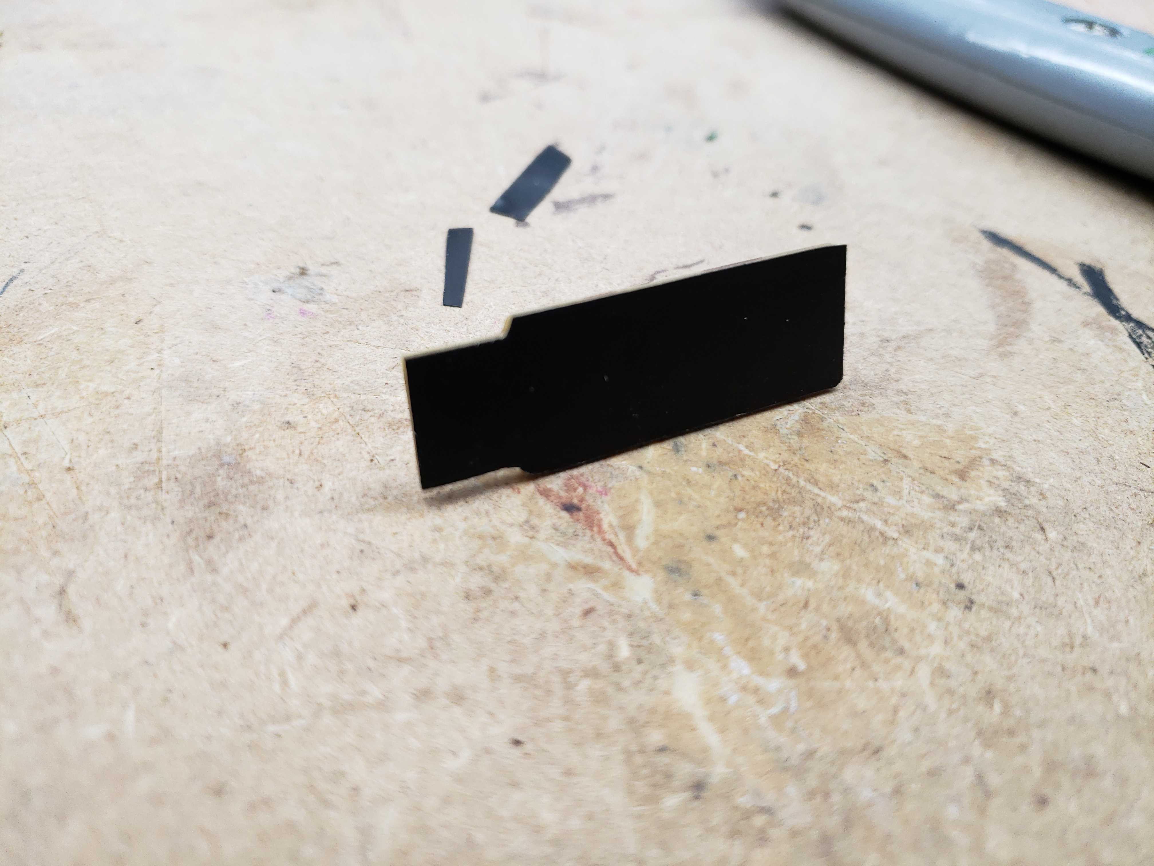
For the finishing touch, I took advice from my brother, William, and cut out an eletrical tape back to the board using a utility knife. The added width of the tape allows the USB male end to have better contact with the computer’s female port.
Programming the programmers
Turning the FabTinyISP boards into functional programmers was a difficult process because the Windows process was significantly more convoluted than Linux or MacOS.
First, we downloaded the depedencies required to flash the programmers.
- AVR Dude
- AVR-GNU Toolchain (Requires an account)
- Make
Since Make came in a installer exectuable, the installation was done by executing the installer.
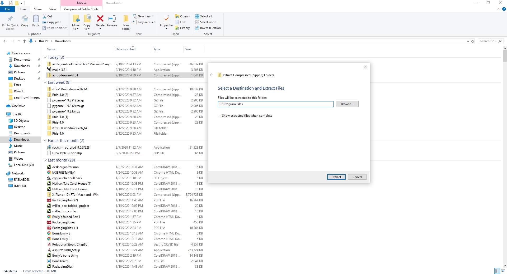
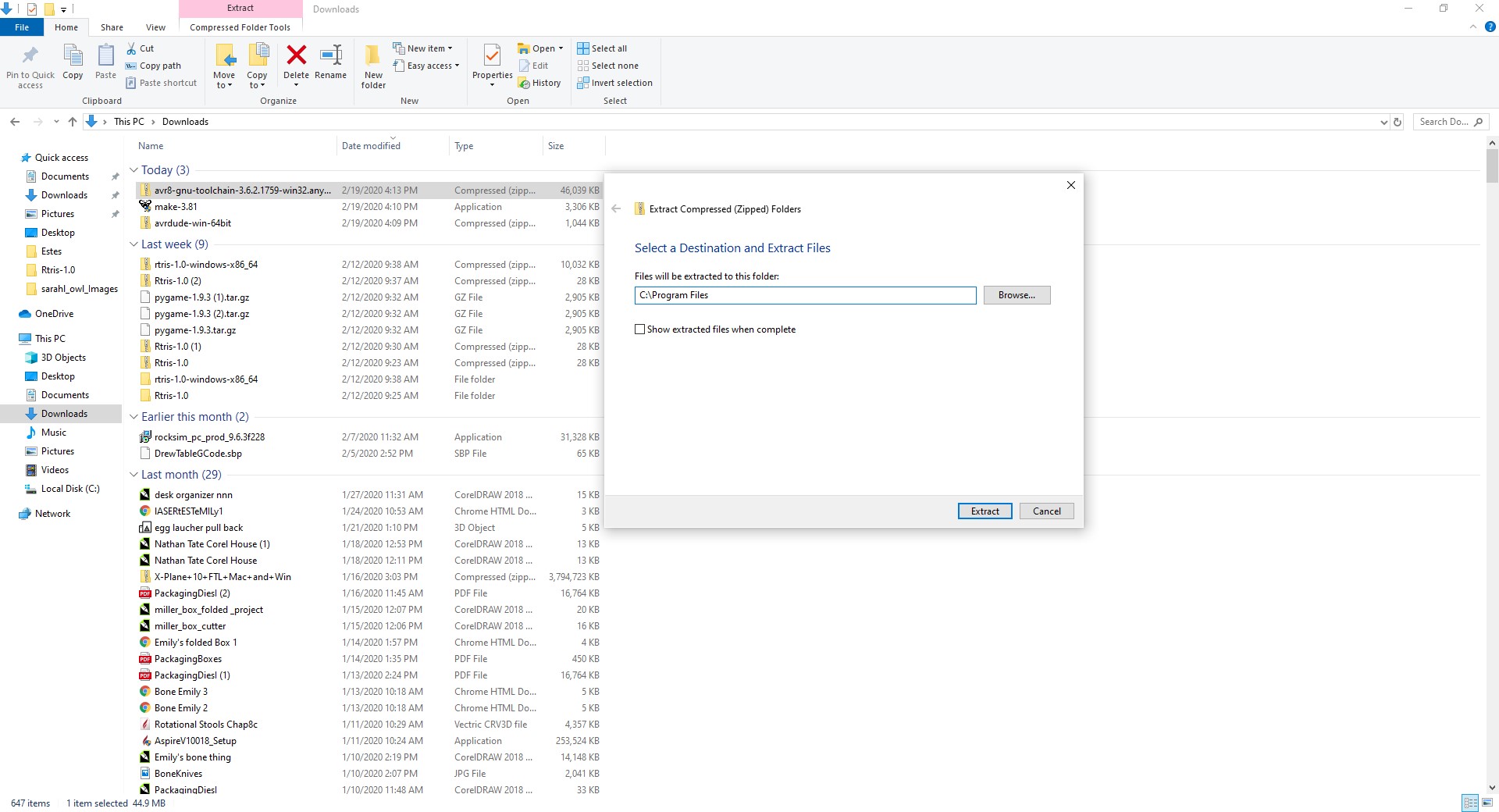
Dependecies that came in a ZIP folder were extracted to the C:\Program Files folder.
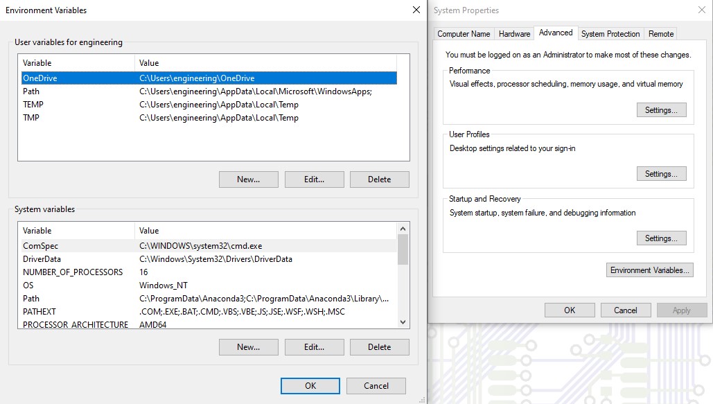
With the dependencies installed, it was time to update the PATH environment variable with the locations of the dependencies. By using the Windows search, we located the dialog box to edit environment variable.
However, we had an issue with the file paths given in the guide. The guide gave us these paths to input into the PATH variable:
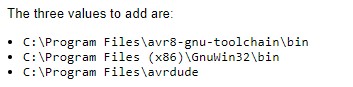
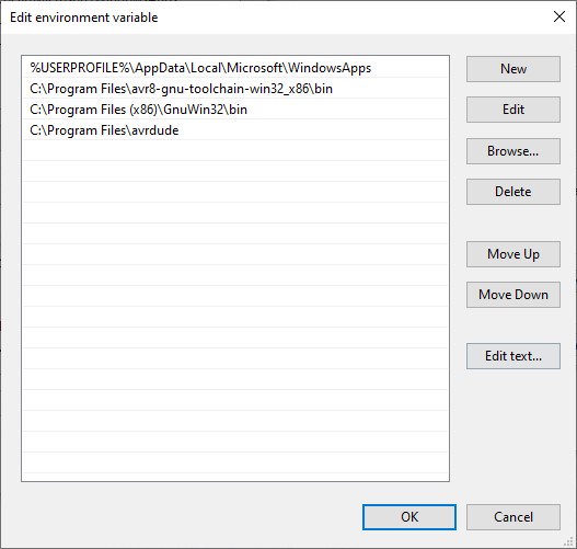
In reality, the name of the AVR Toolchain that we extracted into C:\Program Files was slightly different than the name in the guide. The actual file paths were these:
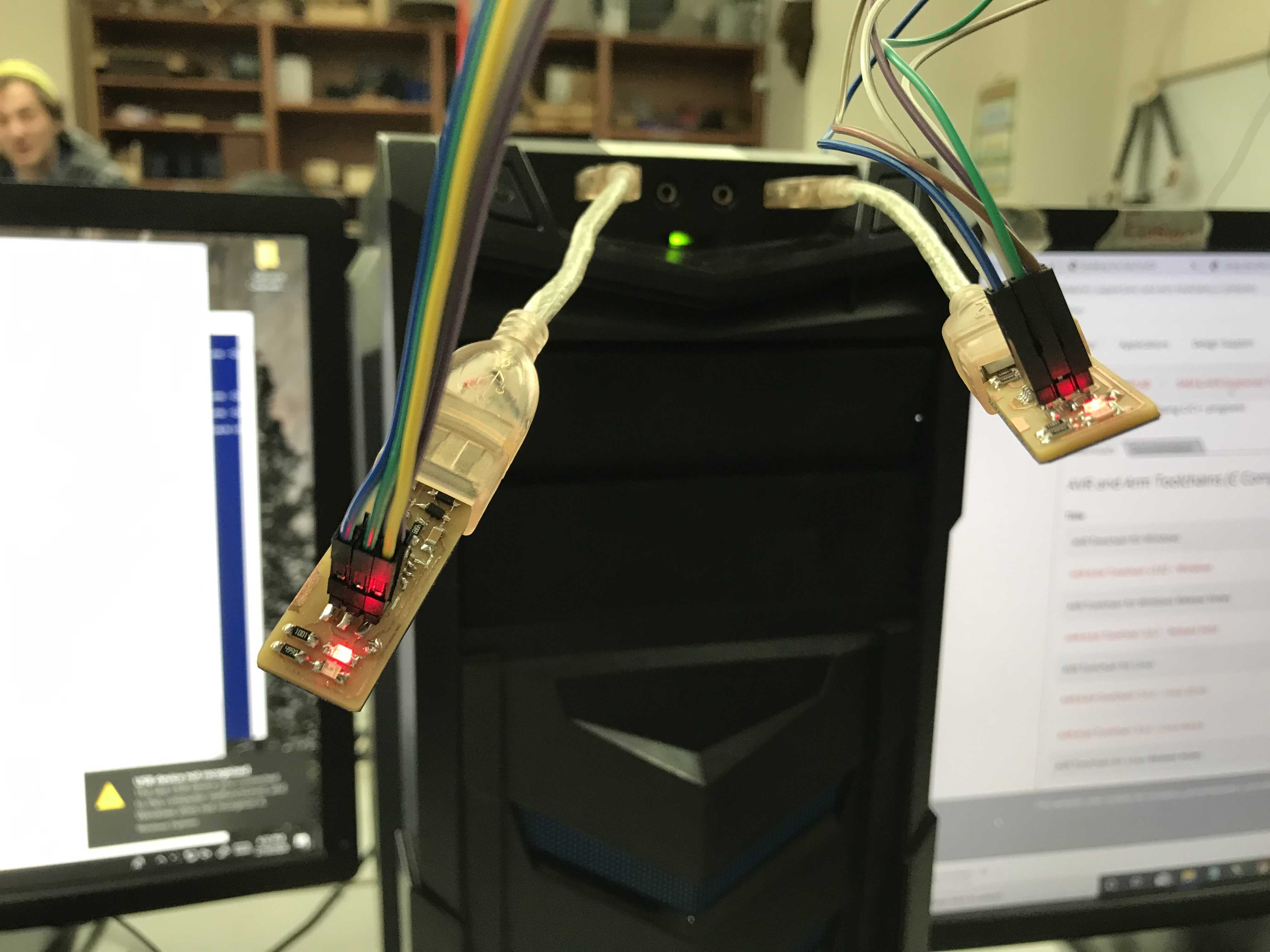
Next, I attached 6 wires from the pins on my brother’s programmer to the pins on my programmer in the same orientation.
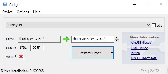
We downloaded Zadig to install the drivers for my brother’s programmer.
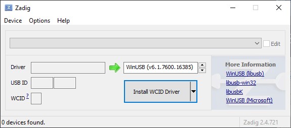
In order to see my brother’s programmer in the dropdown menu, we had to choose Options > List All Devices. We selected my brother’s programmer named USBTinyISP. Then, we selected the libUSB drivers to be installed and clicked the install button.
With all the required setup done, it was time to actually flash firware onto my board. We opened up a Powershell terminal and navigated to the directory containing AVR Dude.
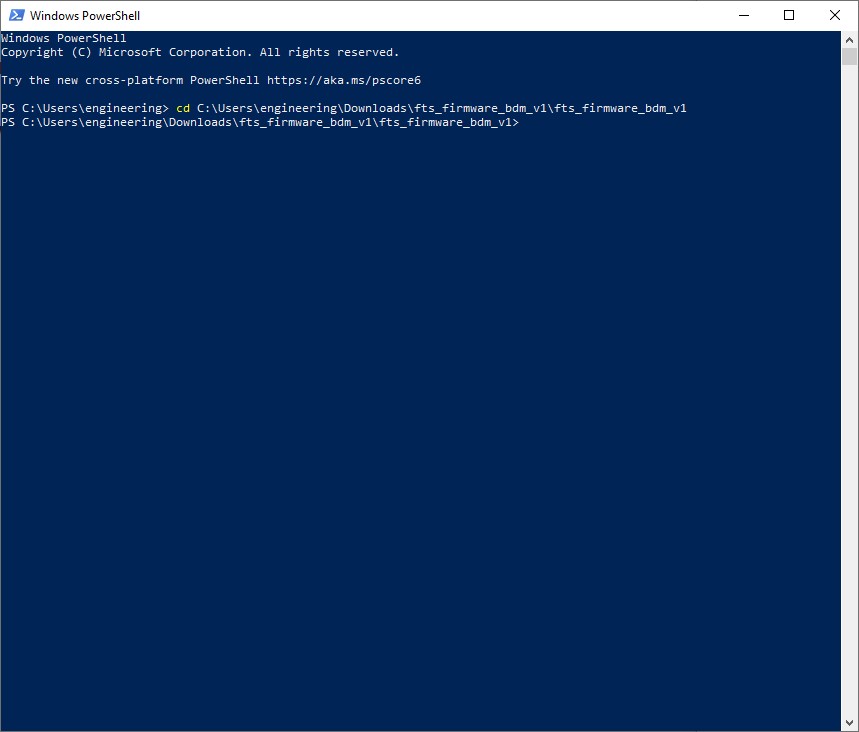
Then, we issued commands in the following order:
make allmake flashmake fusesmake rstdisbl
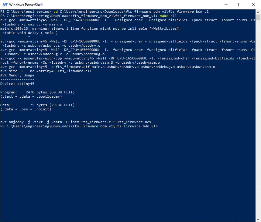

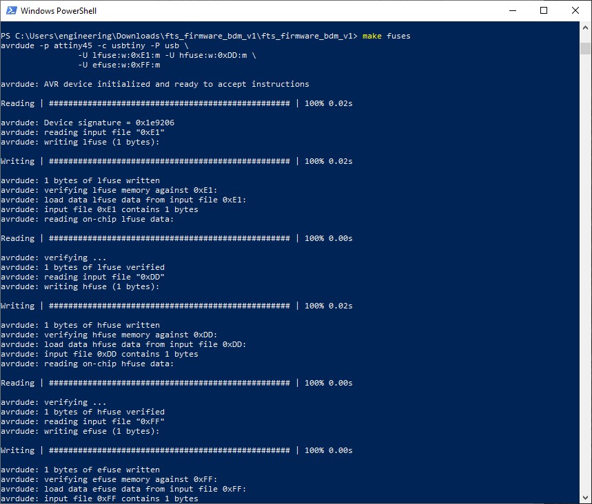
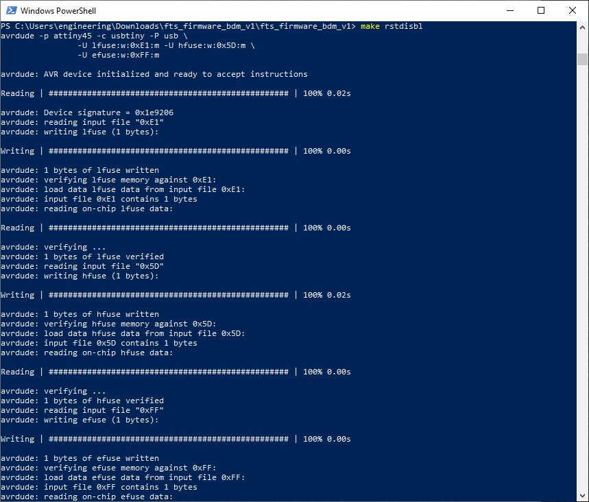
After the firmware was sucessfully flashed onto my board, I used soldering wick to desolder the solder bridge and now I had a fully functioning programmer. To test the programmer, I plugged my programmer into a PC and it sucessfully recognized the programmer as a USBTinyISP. Then, I used my programmer to program Harry’s programmer using the following steps above.
Group Project
During the group project, I helped navigate and experiment with Fab Mods to produce the desired g-code paths for the ruler.