4. Computer controlled cutting
Group Assignment:
- characterize your lasercutter’s focus, power, speed, rate, kerf, and joint clearance
Individual Assignment:
- cut something on the vinylcutter
- design, lasercut, and document a parametric construction kit, accounting for the lasercutter kerf, which can be assembled in multiple ways, and for extra credit include elements that aren’t flat
Vinyl Stickers
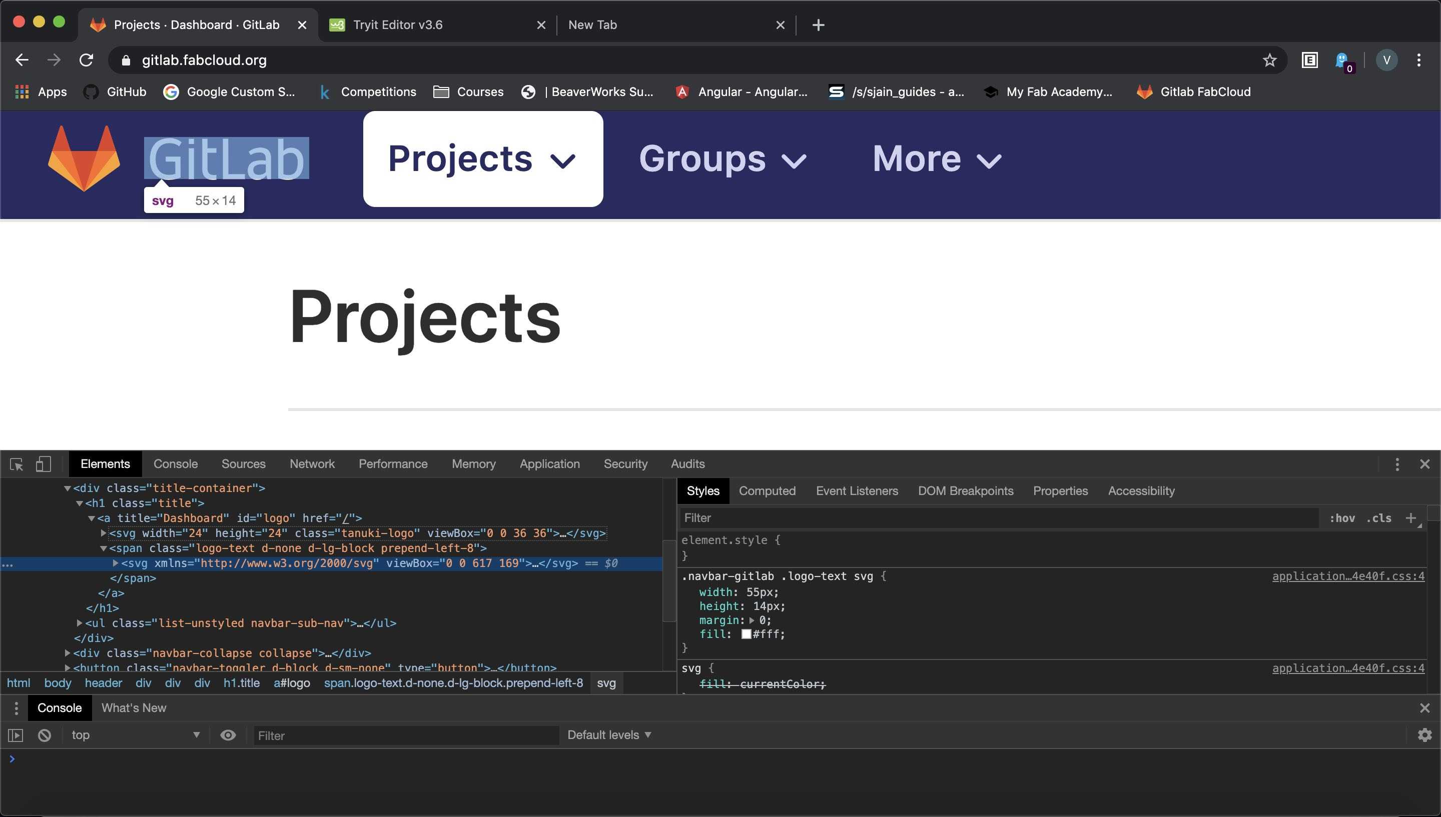
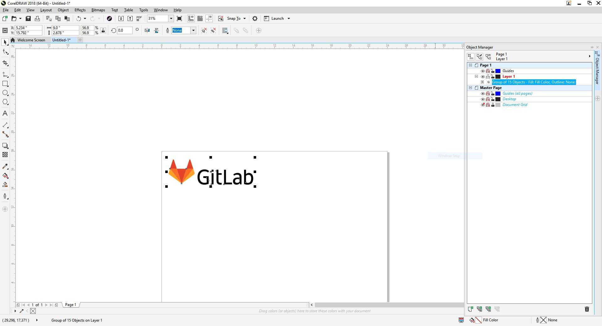
Seeing the stickers made by Charlotte Latin Fab Academy alumni inspired me to create multi-colored stickers. In particular, Kai Vincent created a sticker with correctly colored Fab Academy and Charlotte Latin logos. I decided to create a sticker with a correctly colored GitLab logo. However, in order to do so, I would need to extract a high resolution picture of the GitLab logo. I could have used Google Images to find an image, but I decided to extract the logo from the GitLab website. Using the Inspect Element tool of Chrome, I found the <SVG> tags that stored the SVG data.
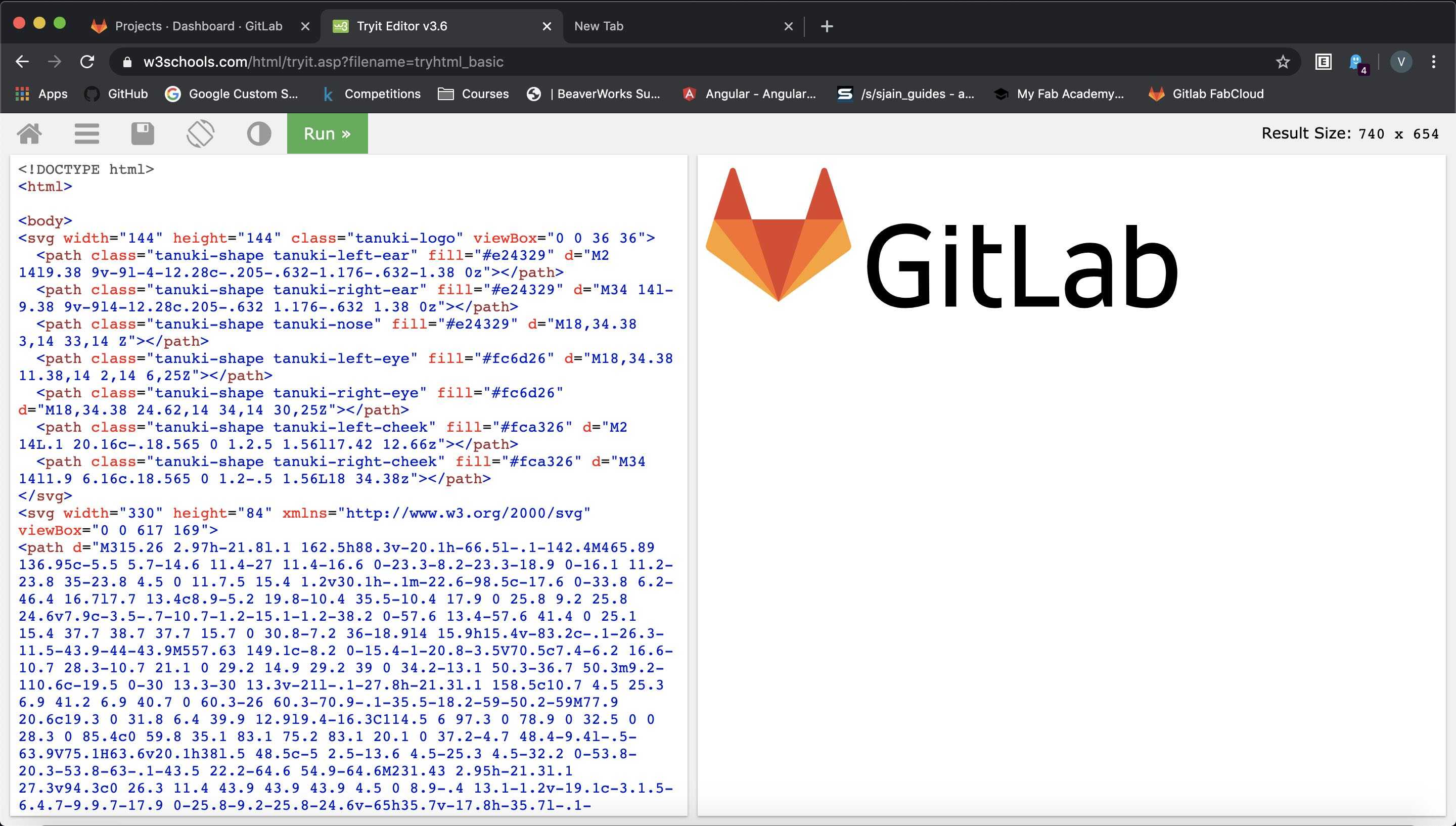
I transfered the points over to an HTML Try-It editor by W3Schools. Intially, the Tanuki (the GitLab mascot) and the textwas too small and the text was unproportional to the Tanuki. To remedy the problem, I added width and attributes to the SVG tags to properly size the logo. Then I took a large screenshot of the result.
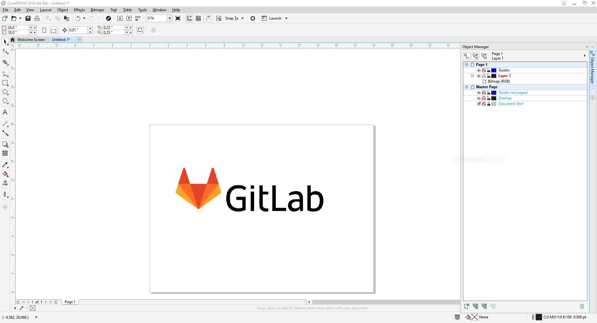
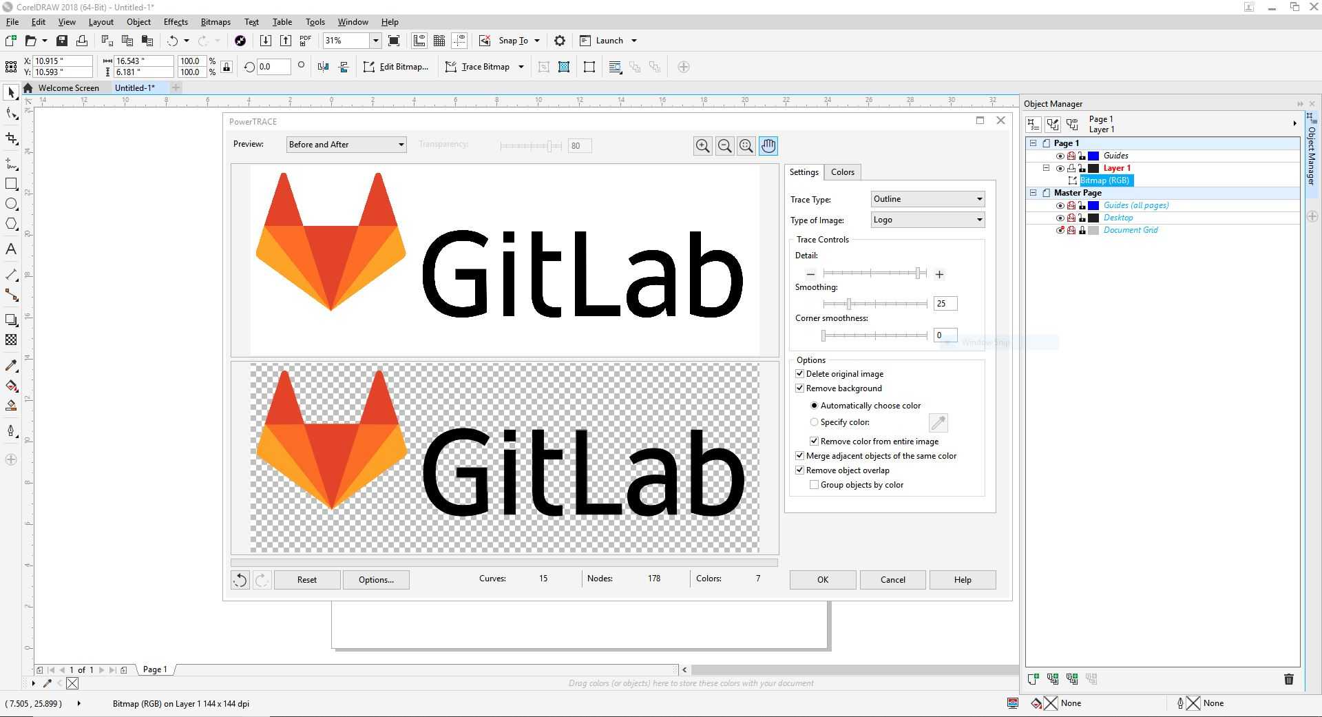
After obtaining a high resolution picture of the GitLab logo, I imported the picture into CorelDraw and traced the bitmap.
I resized the vectorized image to a reasonable size so that I could place the sticker on the window where other Fab Academy alumni had placed their sticker as well.
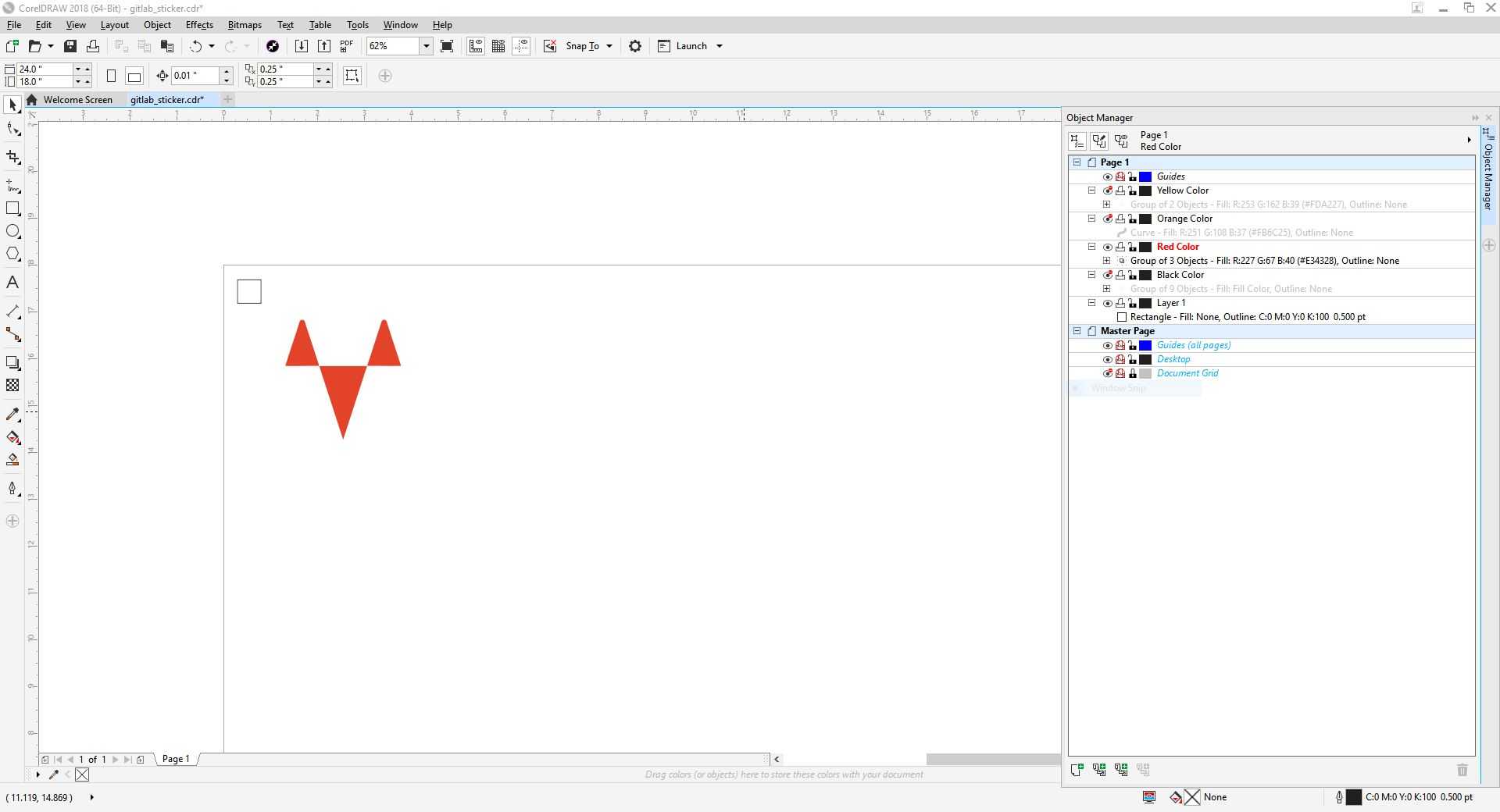
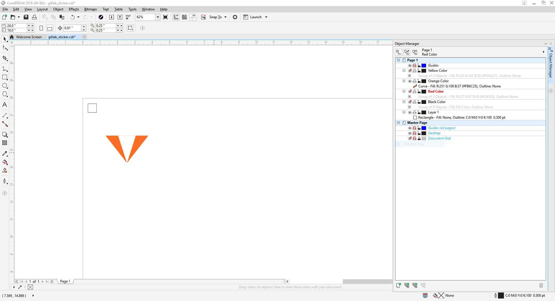
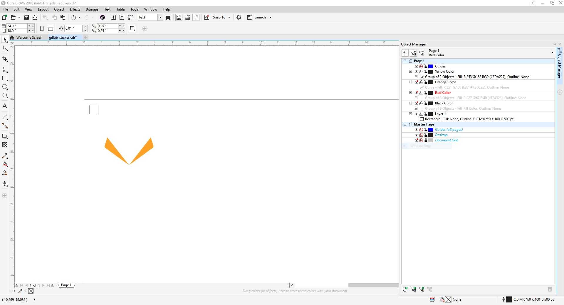
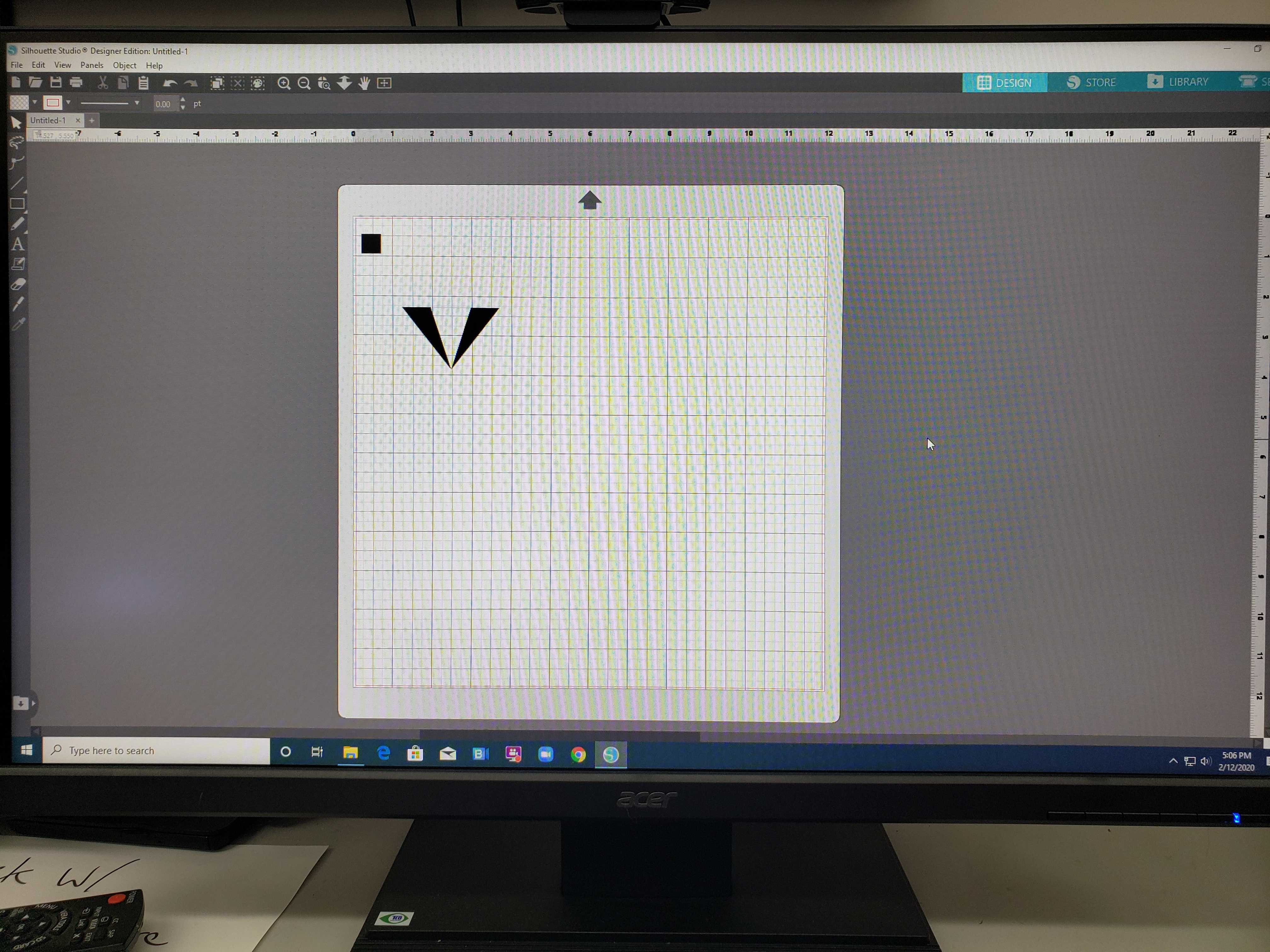
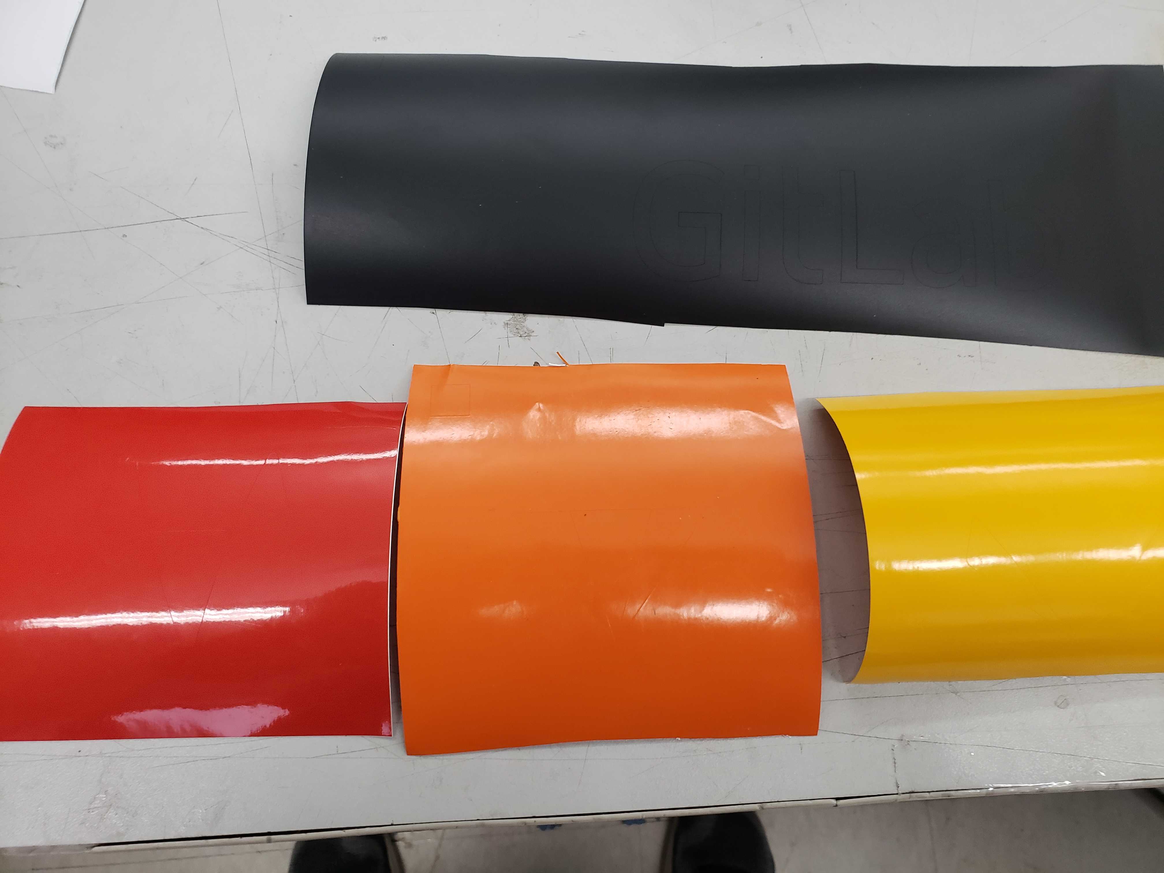
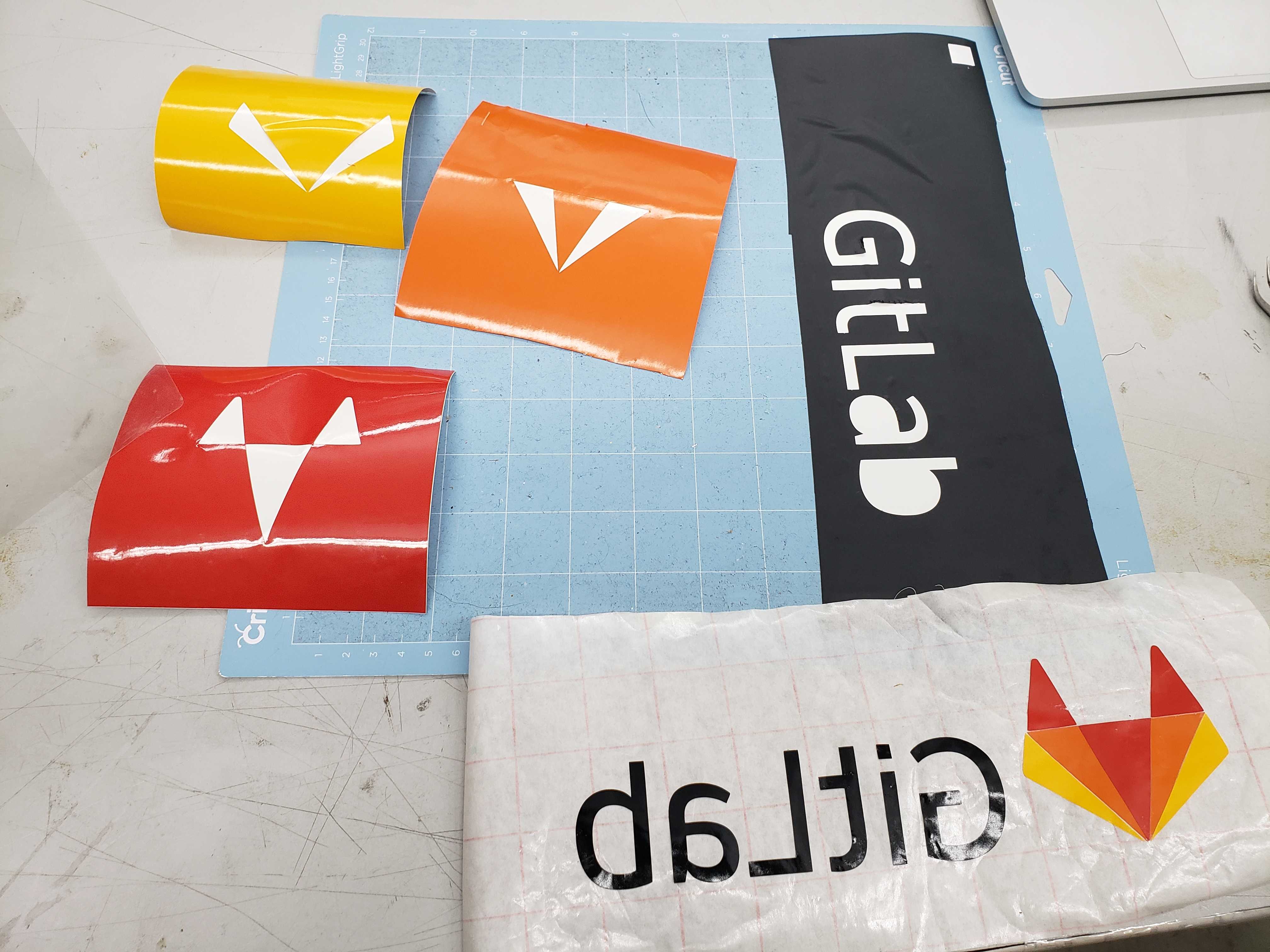
Then, I seperated the color regions of the logo into black, yellow, orange, red layers so that I could cut the colors on seperate colored pieces of vinyl.
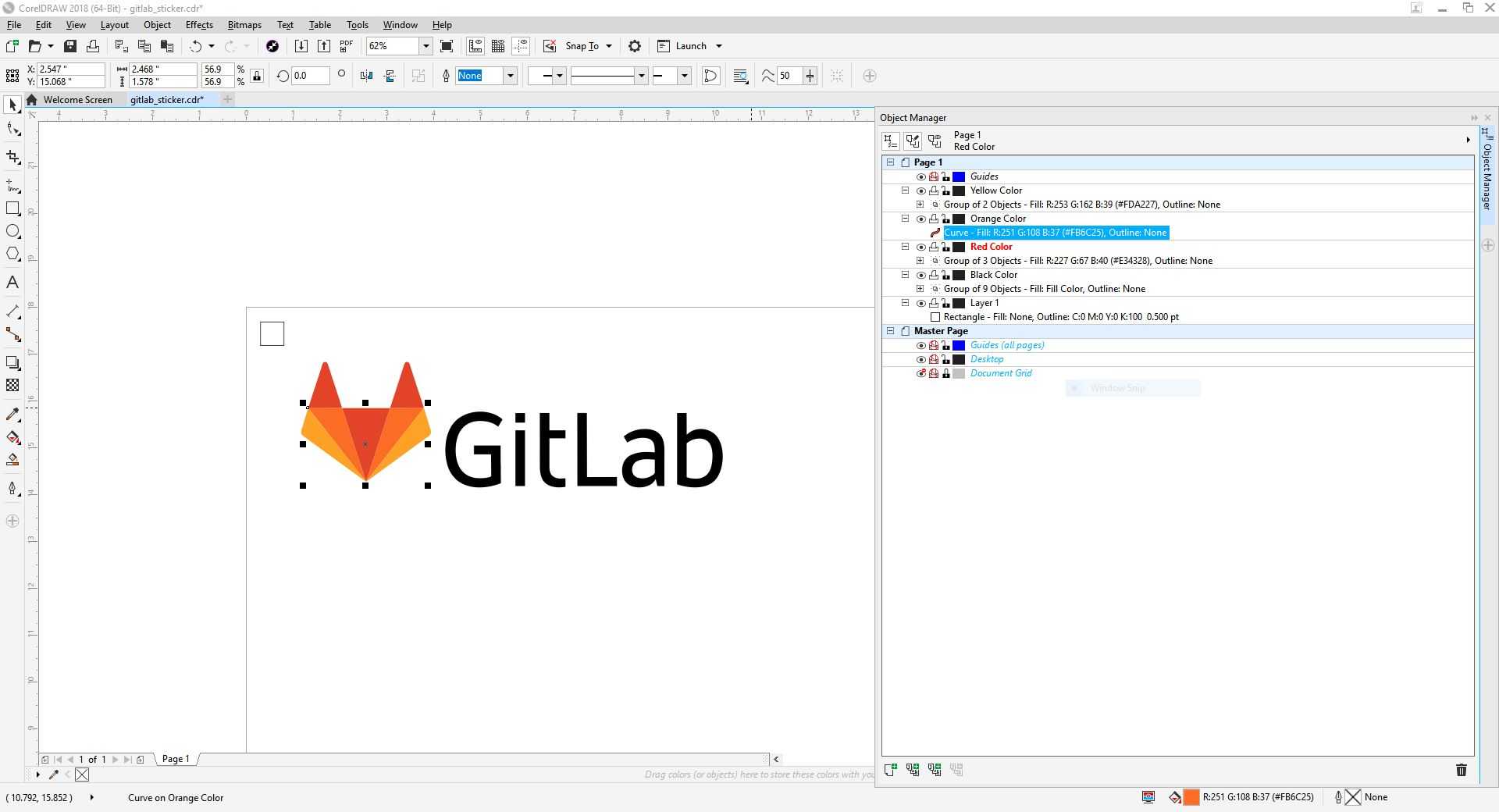
However, an alumni of the Fab Academy program advised me to add shape in the same place on each layer for alignment since I had to cut on different peices of vinyl for each color. I decided to add an alignment box in the top left corner.
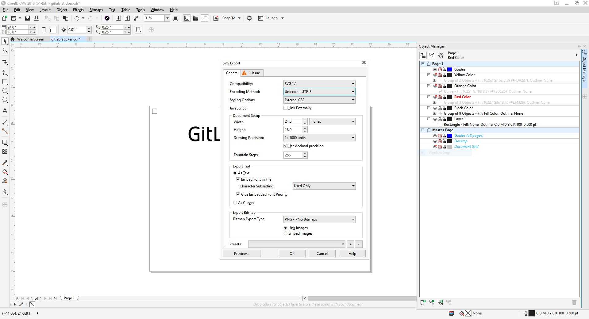
For each color layer, I disabled the printing of the other layers and exported .SVG files of each individual layers.
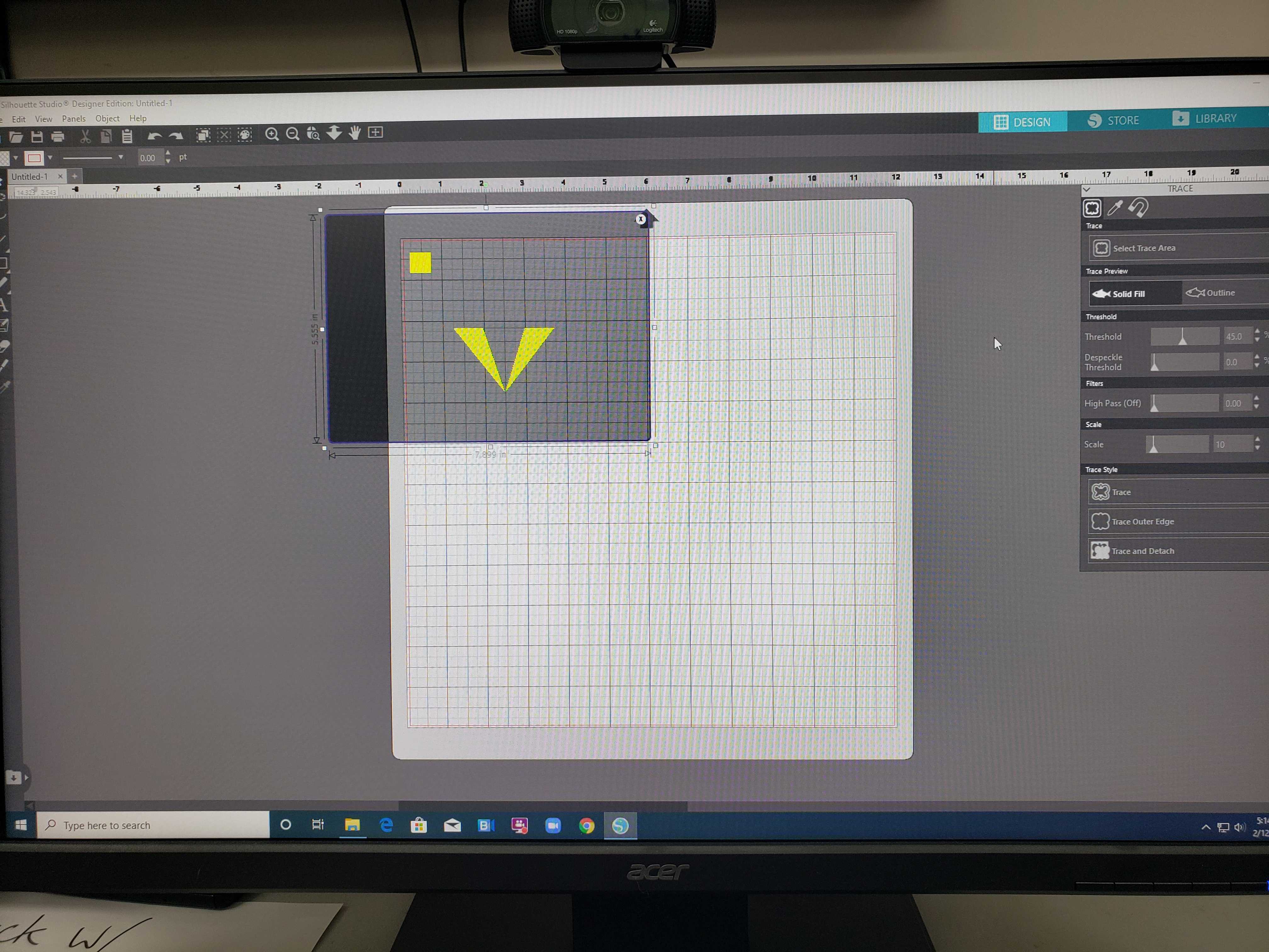
On Silhouette, I imported a .SVG file and used the trace tool to trace the outline.
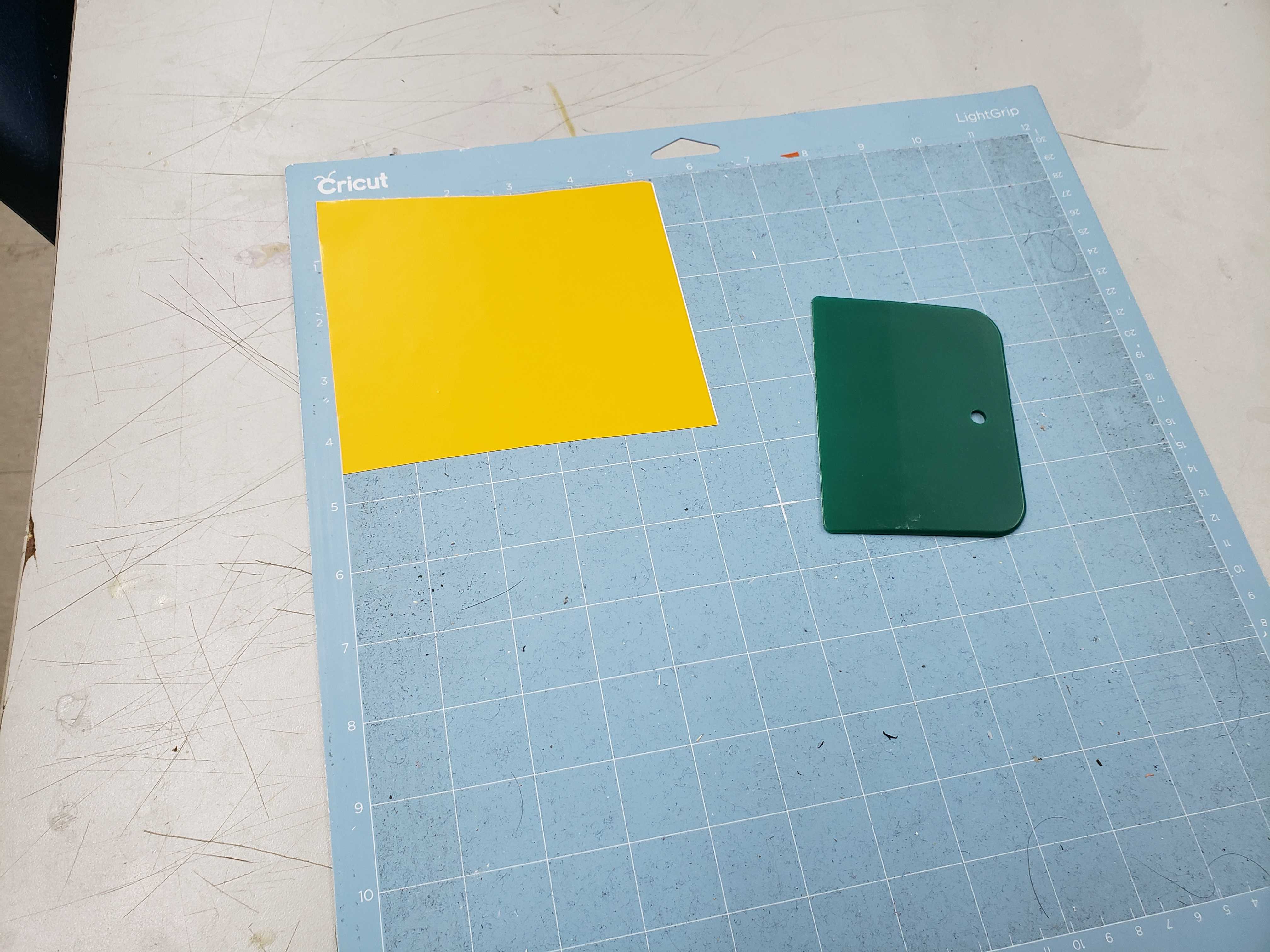
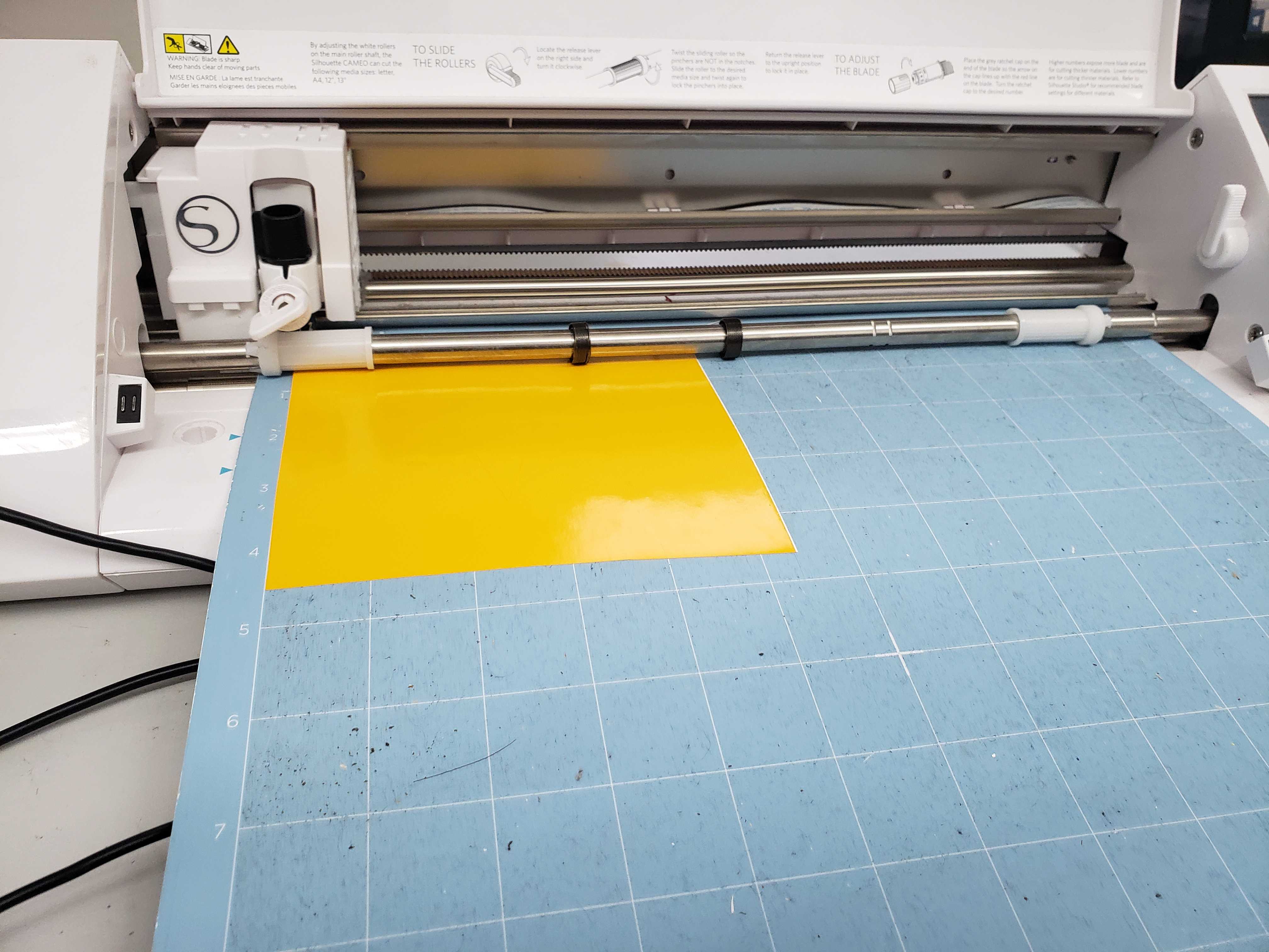
Next, I placed the corresponding color vinyl piece onto a cutting mat and loaded the mat into the vinyl cutter.
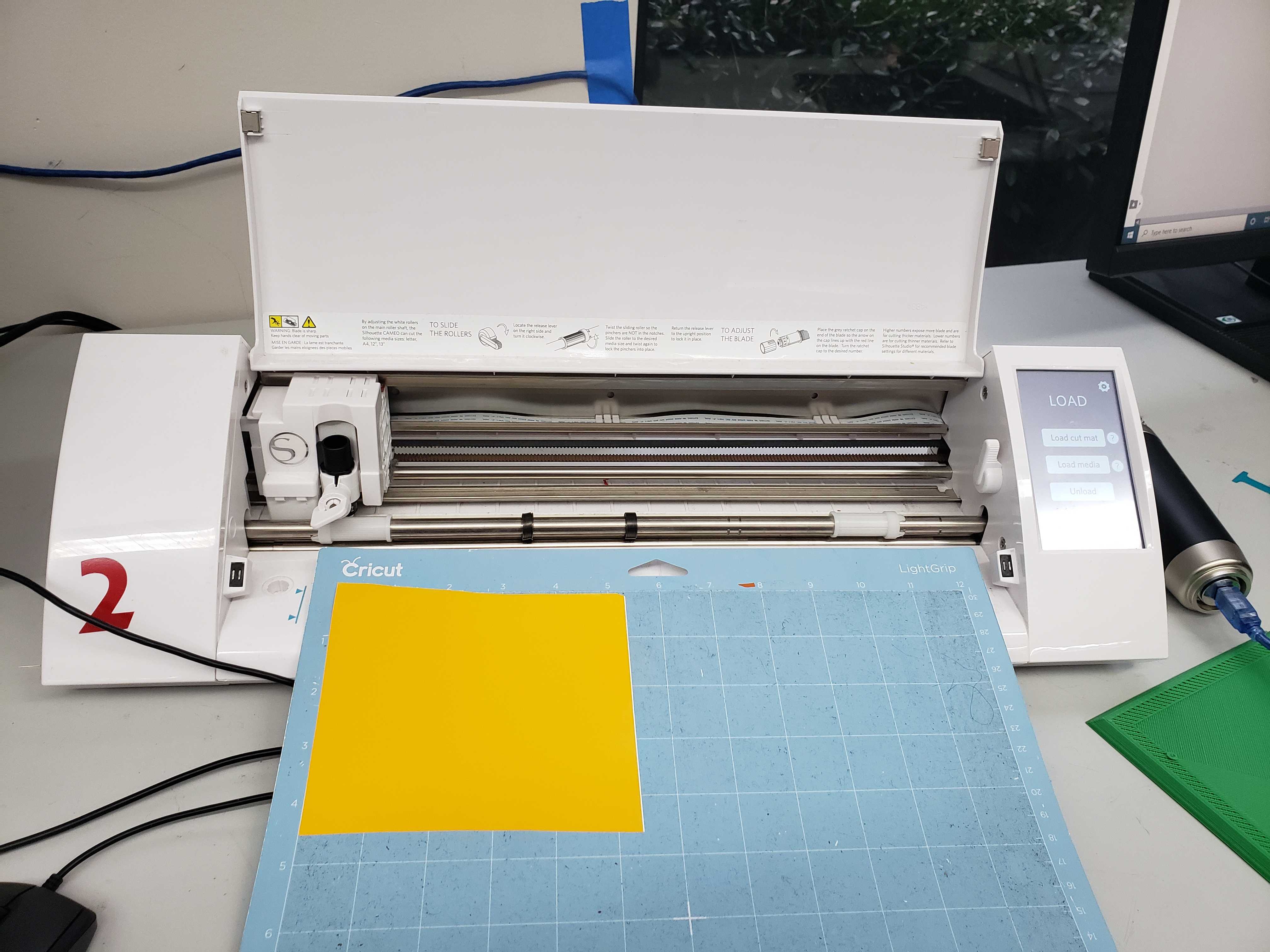
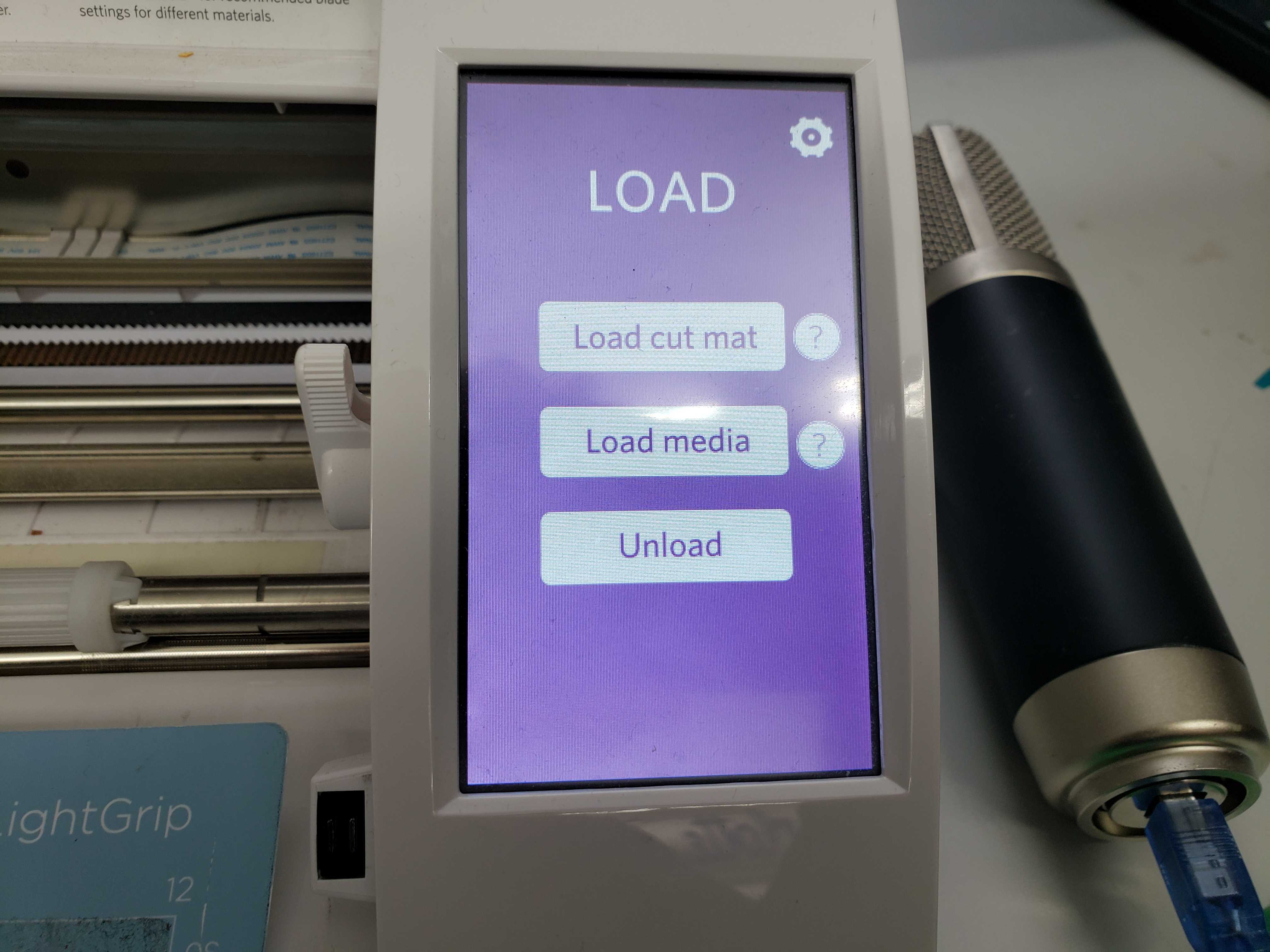
Then, I clicked the “Send to Silhouette” button and the vinyl cutter automatically started cutting. I repeated this process for each color.
To combine all the cut vinyl sticker together, I firmly applied transfer paper to one sticker and peeled off the paper. I repeated this step for the other stickers, making sure to align the box.
![]()

Parametric Construction Kit
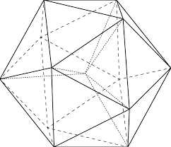
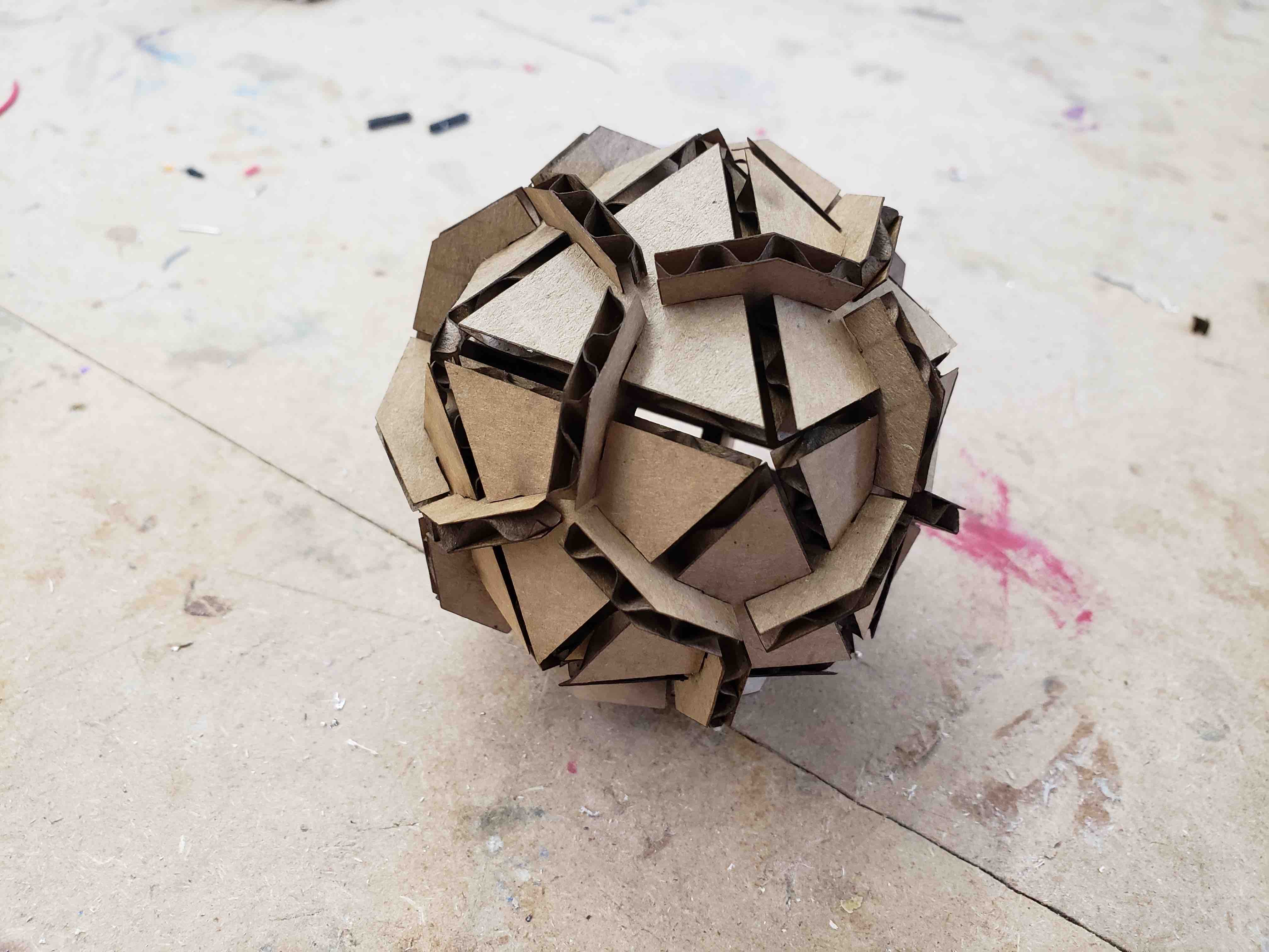
I wanted to create a regular polyhedron using two pieces. I came across a picture of a icosahedron after multiple Google Image searches and decided that I would make the construction kit based upon the icosahedron.
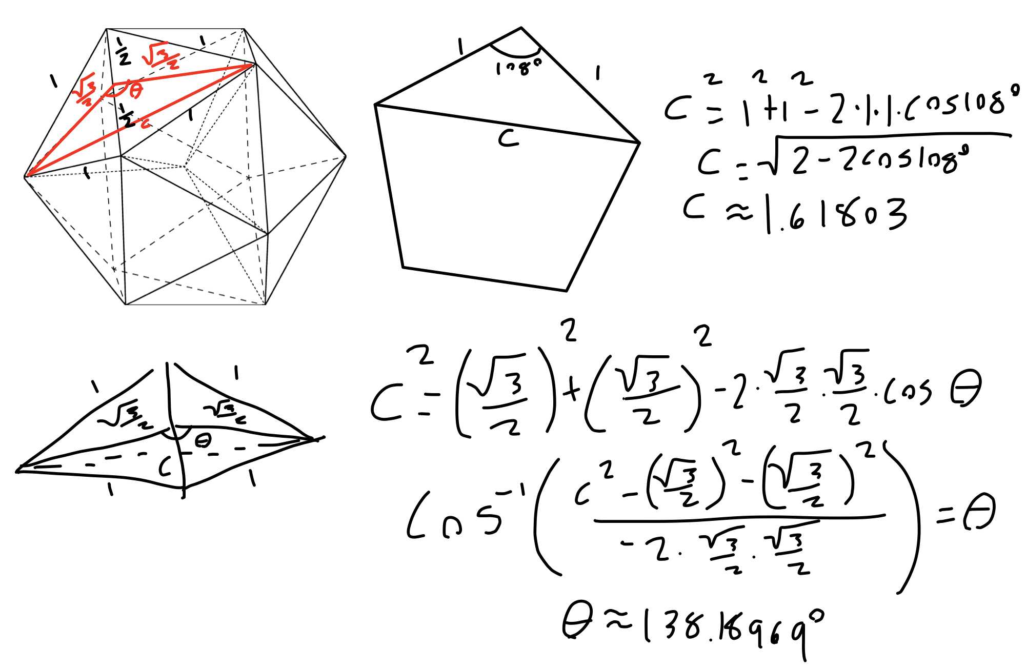
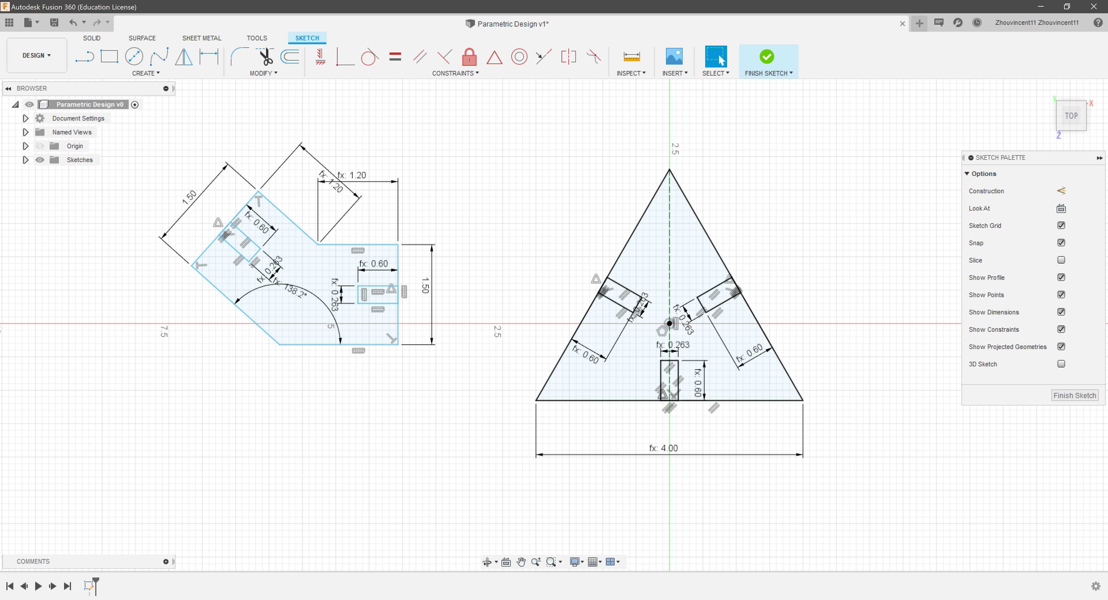
However, determining the angle of the connector proved to be a challenge. First, I realized that the top portion of the isocahdedron made a regular pentagon. I set the sides of the icosahedron to one and found the length of the line connecting two endpoints of two adjacent sides of the pentagon. Second, I determined the altitude of the two adjacent traingles as bisecting the altitude creates two 30-60-90 triangles. Finally, I used the Law of Cosines to determine the angle between the two altitudes and opposite from the line. Now, I know that the conector must have an angle of about 138.18969º.
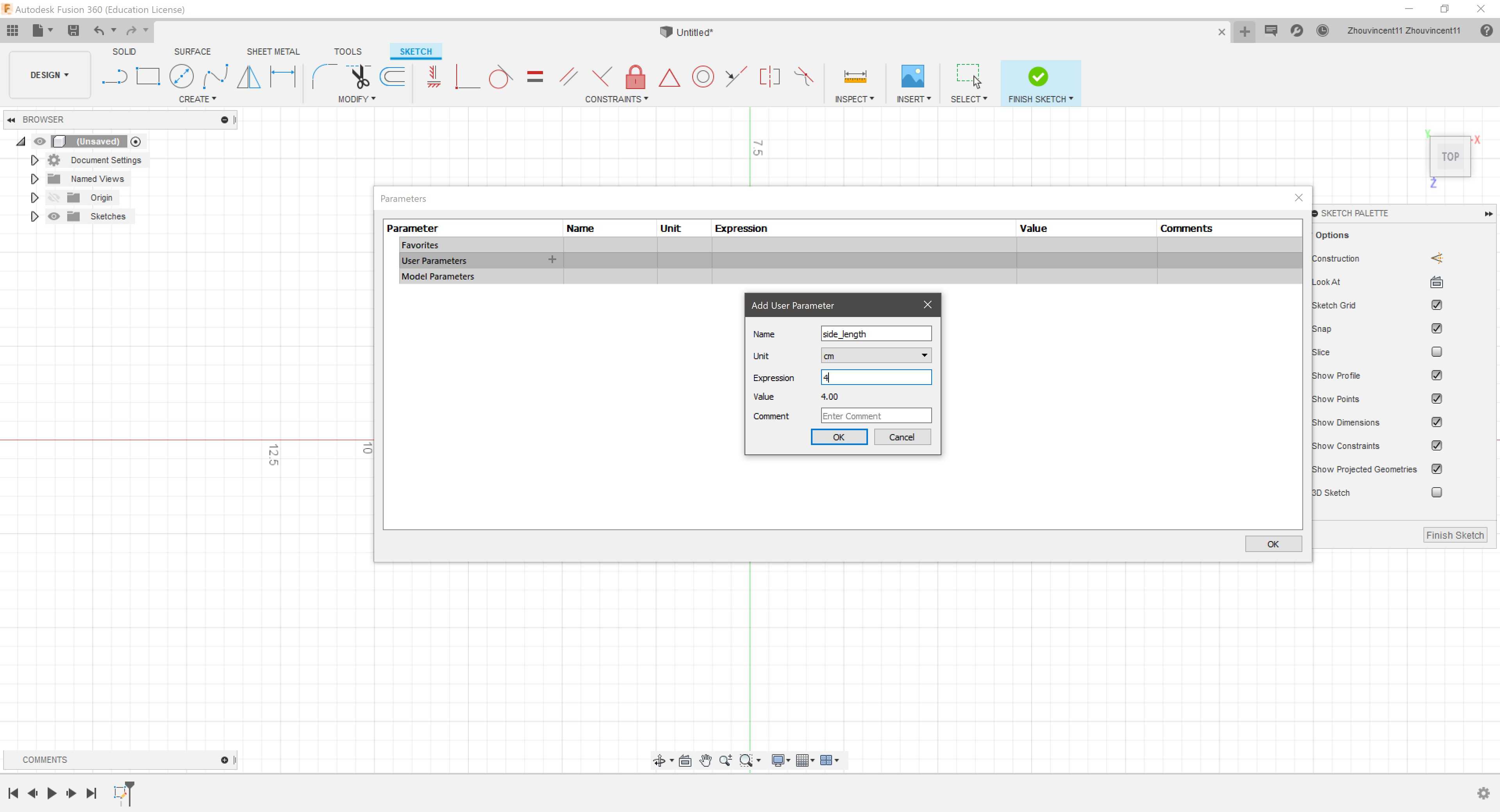
In Fusion 360, I selected the “Change Parameters” tool and I created a new user parameter called “side_length” and set the value to 4 cm.
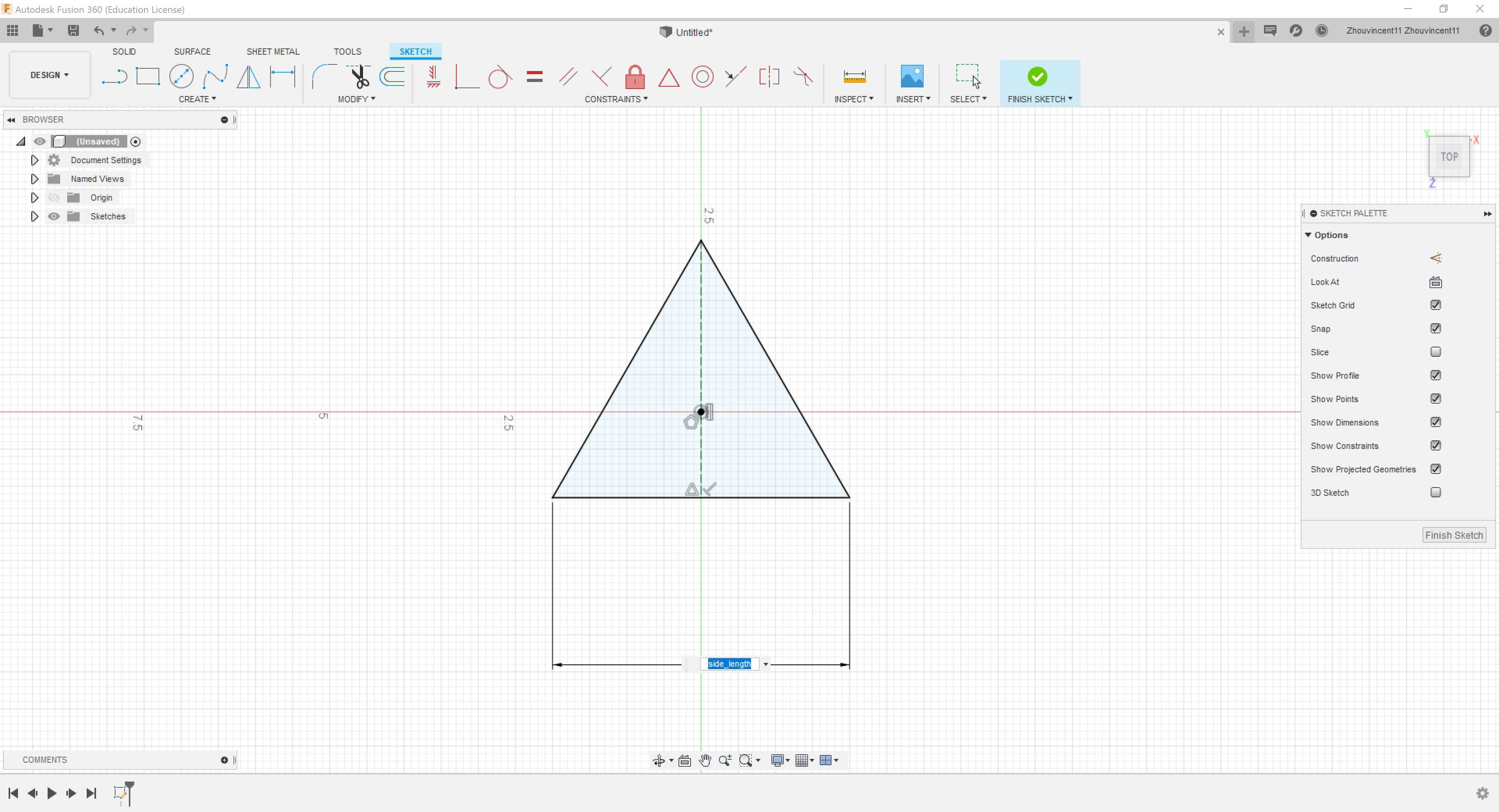
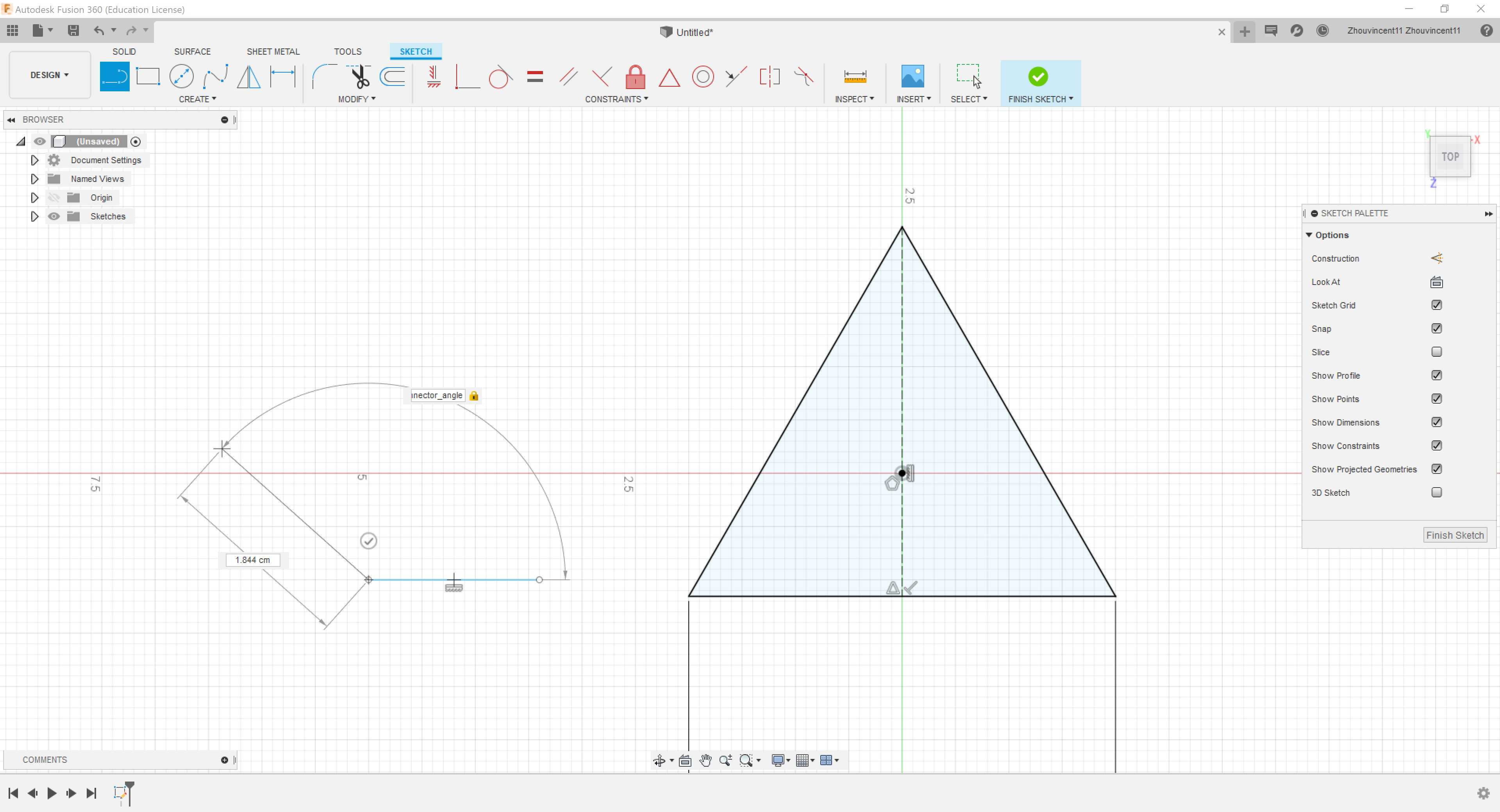
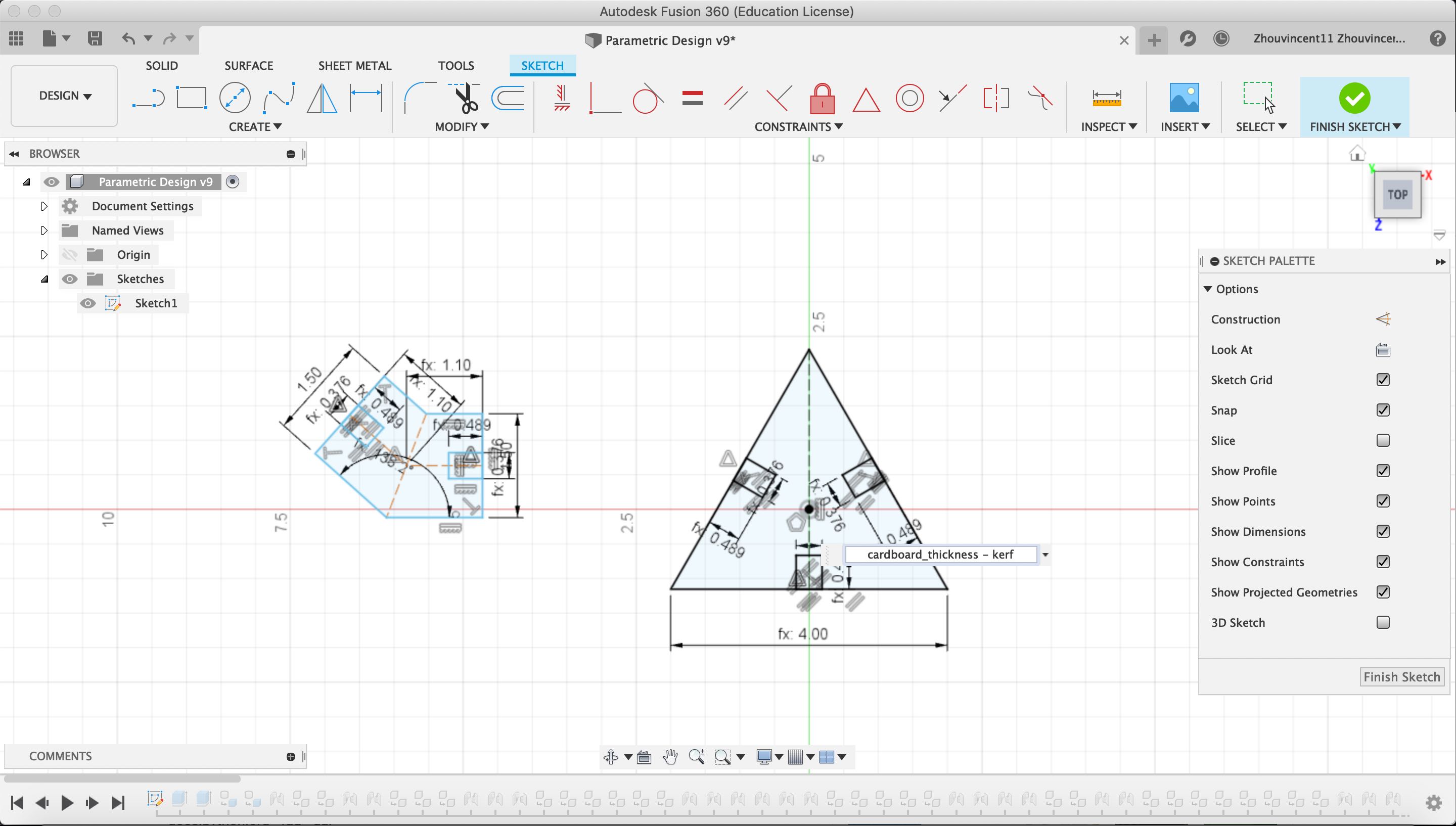
Then, I created a regular triangle on a sketch and dimensioned the side length to the parameter “side_length”.
Next, I added another user parameter called “angle” and set the value to 138.18969º.
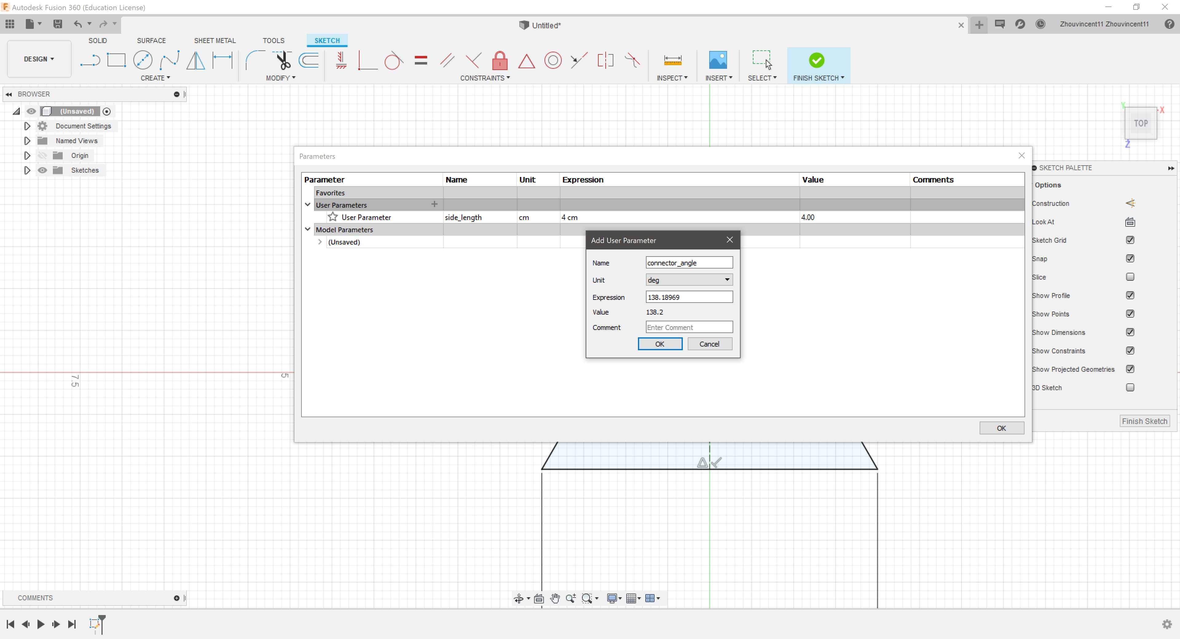
Then, I created two lines and dimensioend the angle between the two liens to the parameter “angle”.
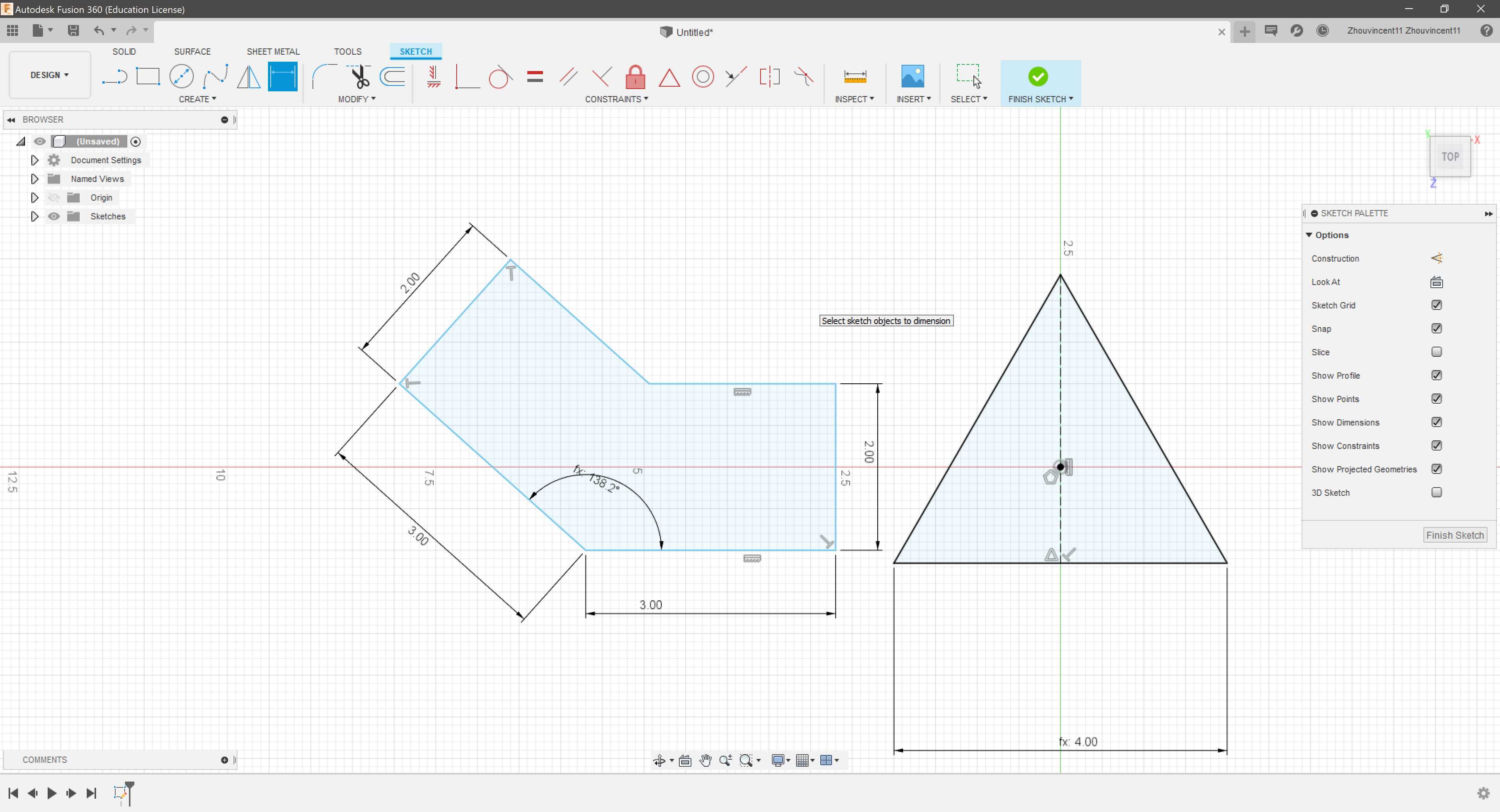
I completed the basic outlines of the connector by creating two perpendicular lines at the ends and two parallel lines. I dimensioned the sides to some arbitrary value that I will change later.
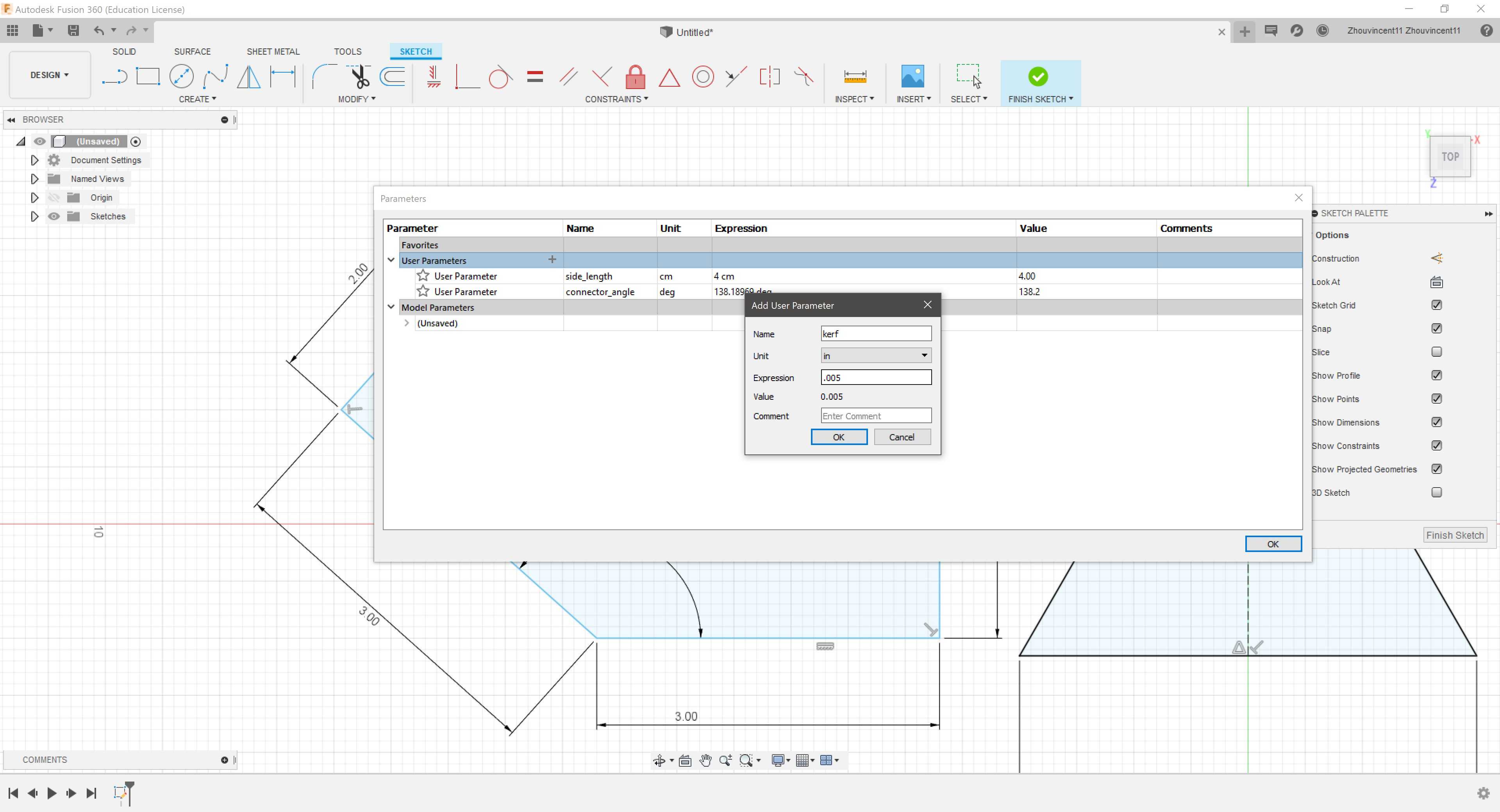
To begin creating the slots, I first added two user parameters called “kerf” set to .005 in. and “cardboard_thickness” set to .25 cm. As I didn’t know the thickness of the cardboard yet, I set the parameter to an estimate.
I created rectangles on the two endes of the conenctor and all three sides of the triangles. Then, I dimensioned the width of all the rectangles to “cardboard_thickness + kerf”.
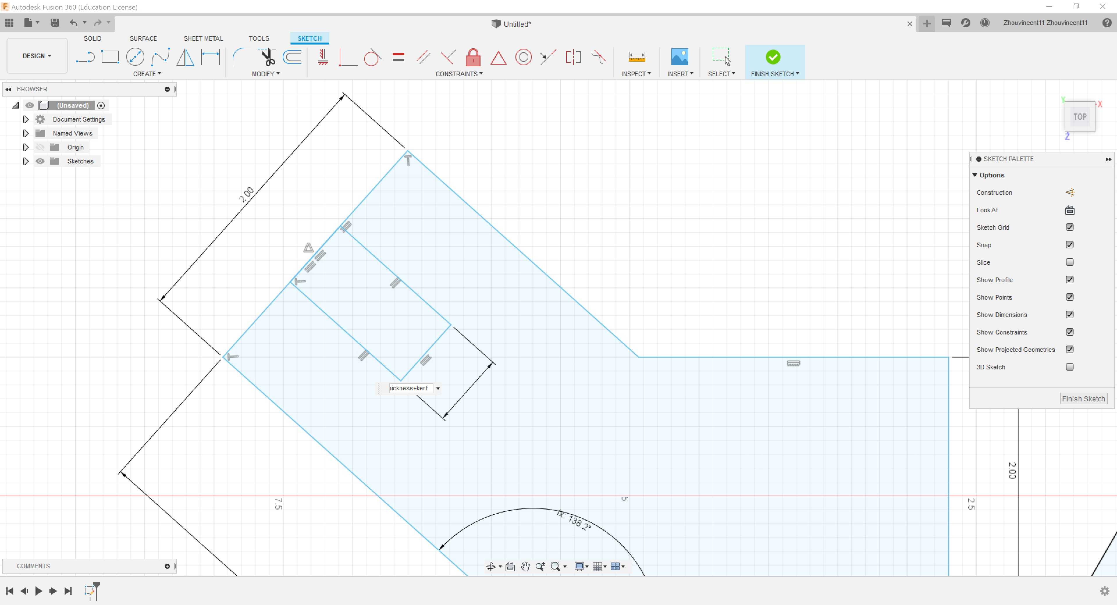
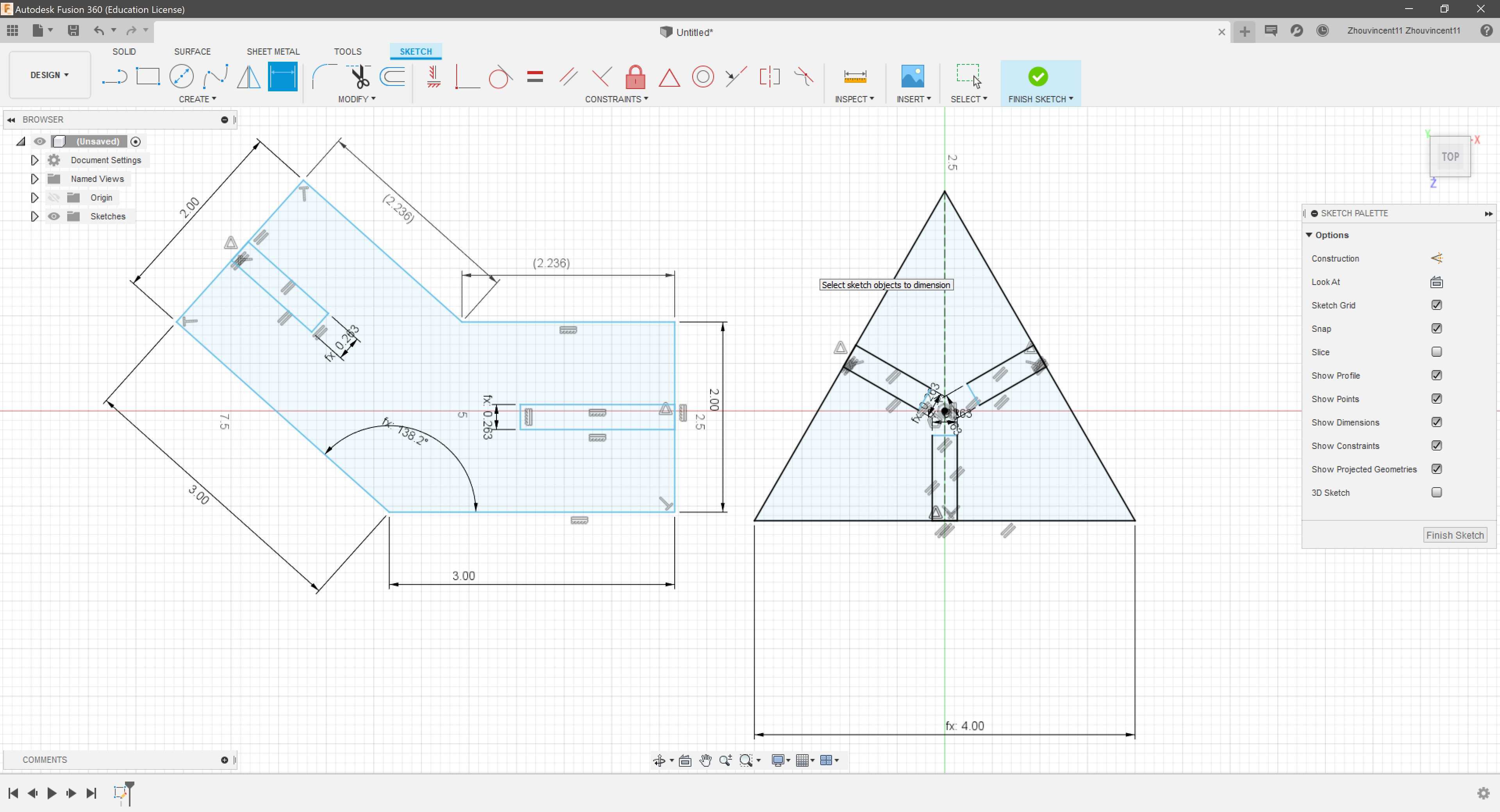
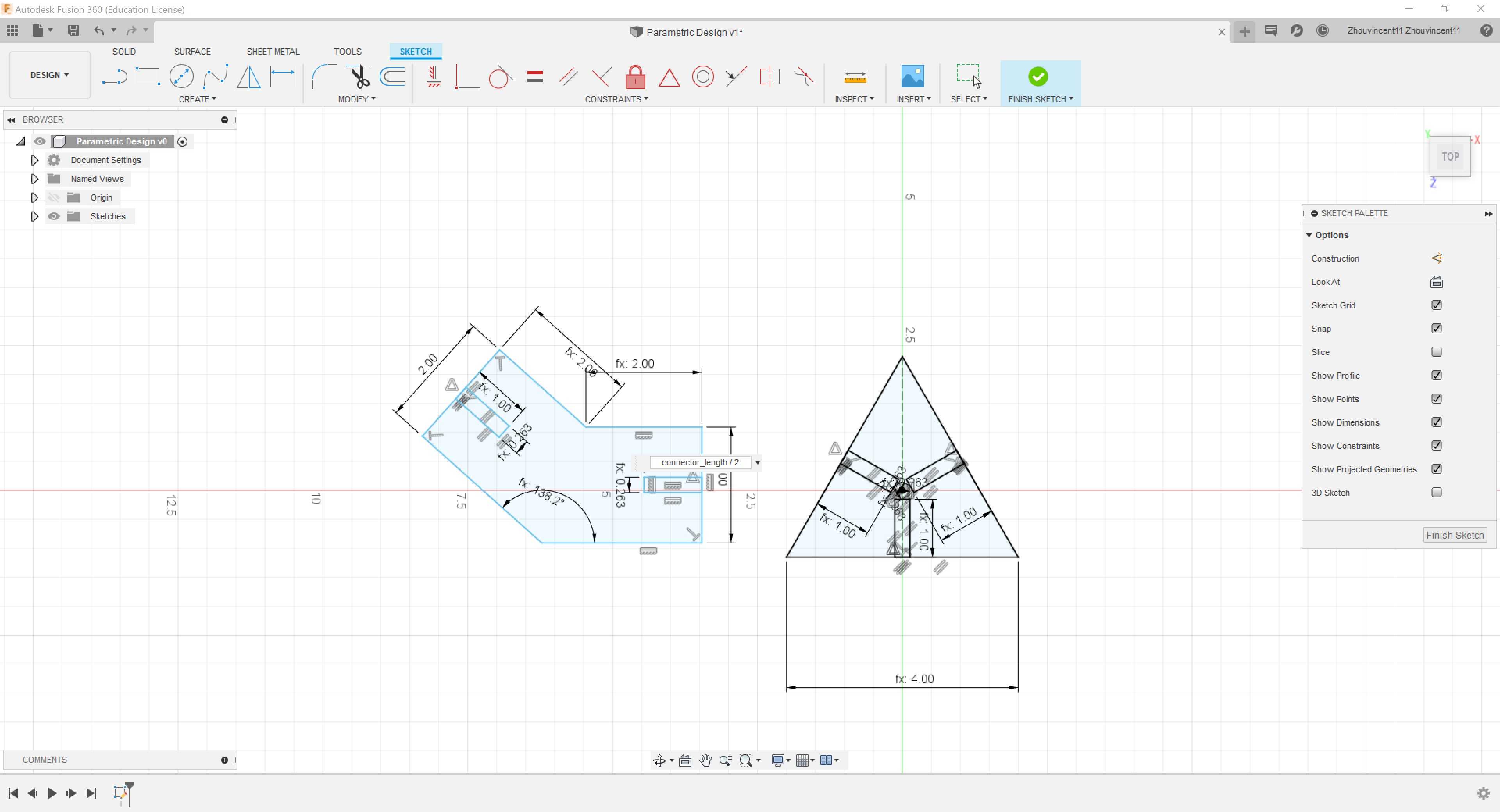
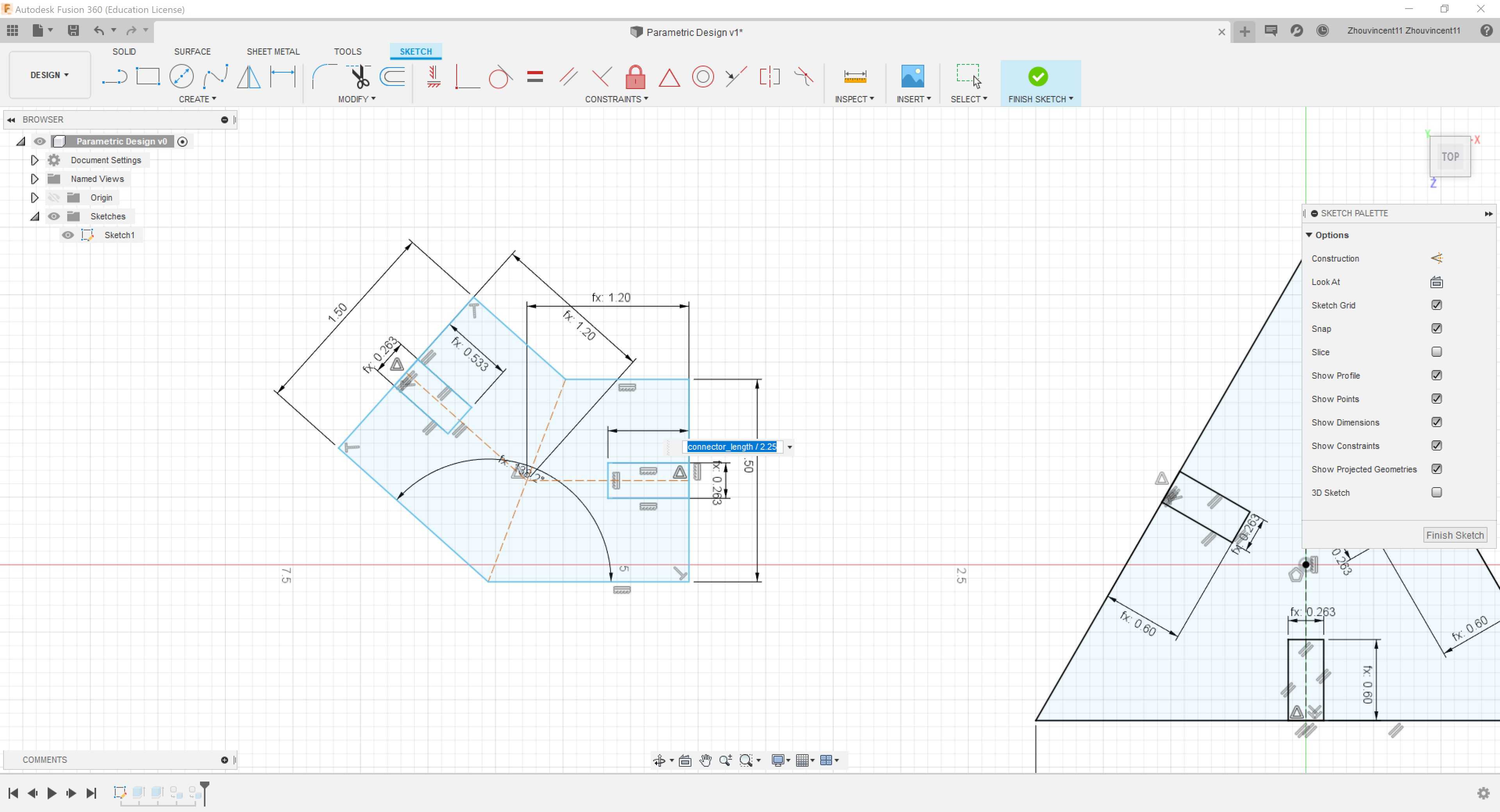
However, I realized that I should dimension the smaller lengths of the connector as the smaller sides wouild provide a better measurement of clearance between joining pieces. I added a parameter called “connector_length” set to 2 cm and reset the connector length dimensions to the parameter. To provide clearance, I set the length of all slots to “connector_length / 2”.
I decided to test the parts by extruding the parts by “cardboard_width + kerf”, converting the bodies into components, and joining them together with joints.
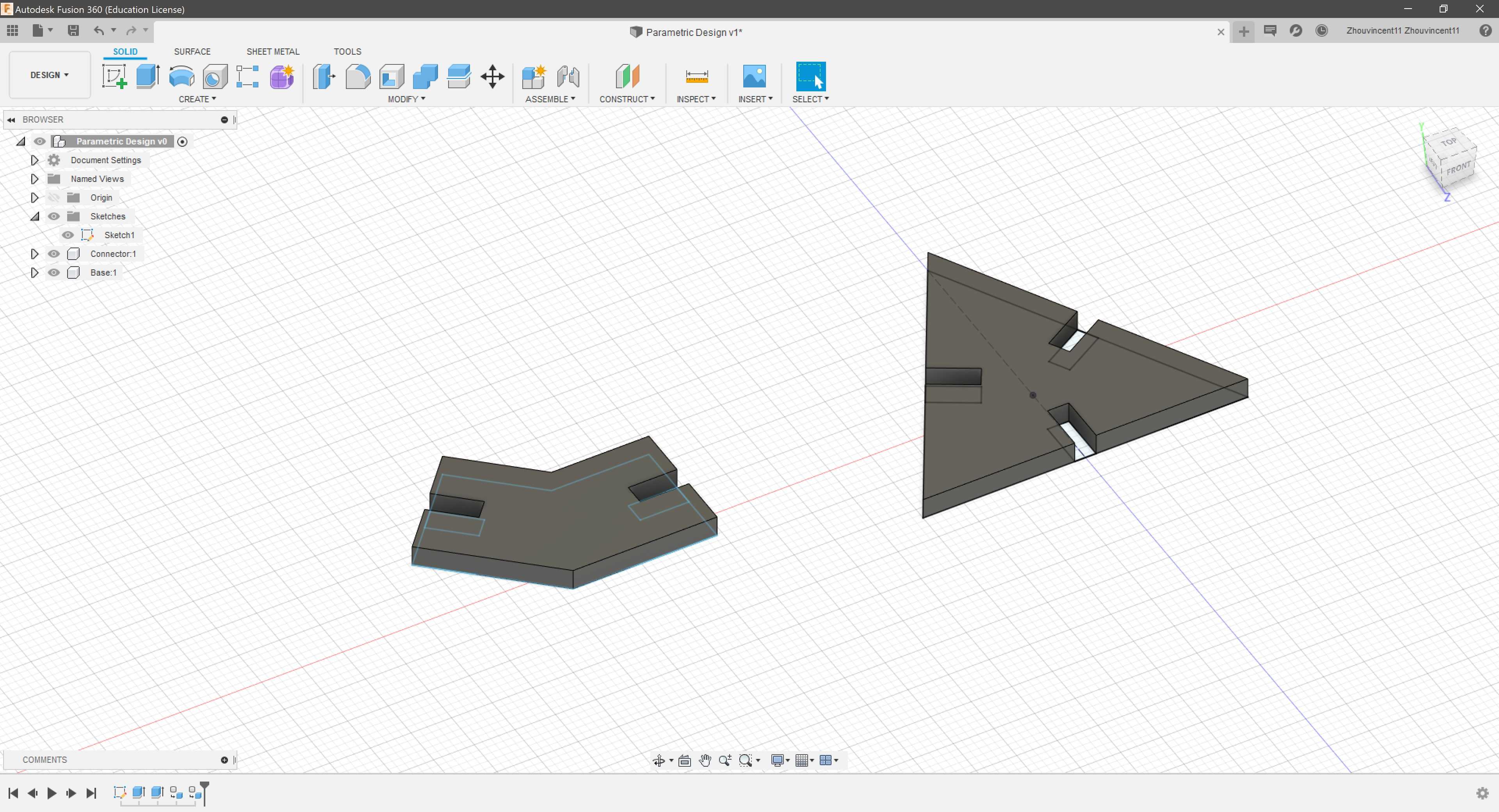
However, the resulting assembly revealed that the connector encroaches upon the space of other connectors.
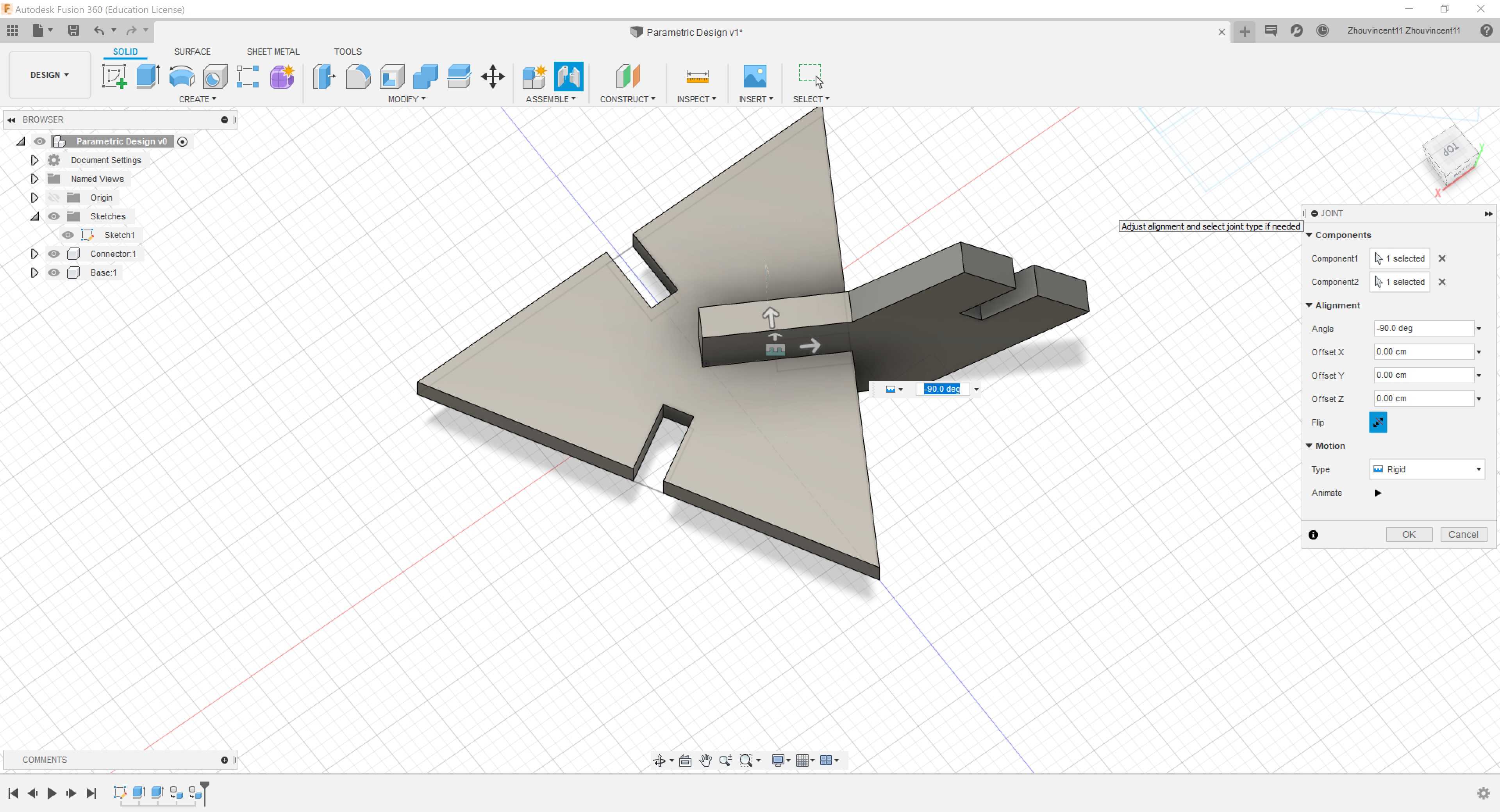
To fix the sketch, I set the length dimension to the middle of the connector with the help of several construction lines. Then, I replaced the length of all slots to “connector_length / 2.25” to add some tolerance.
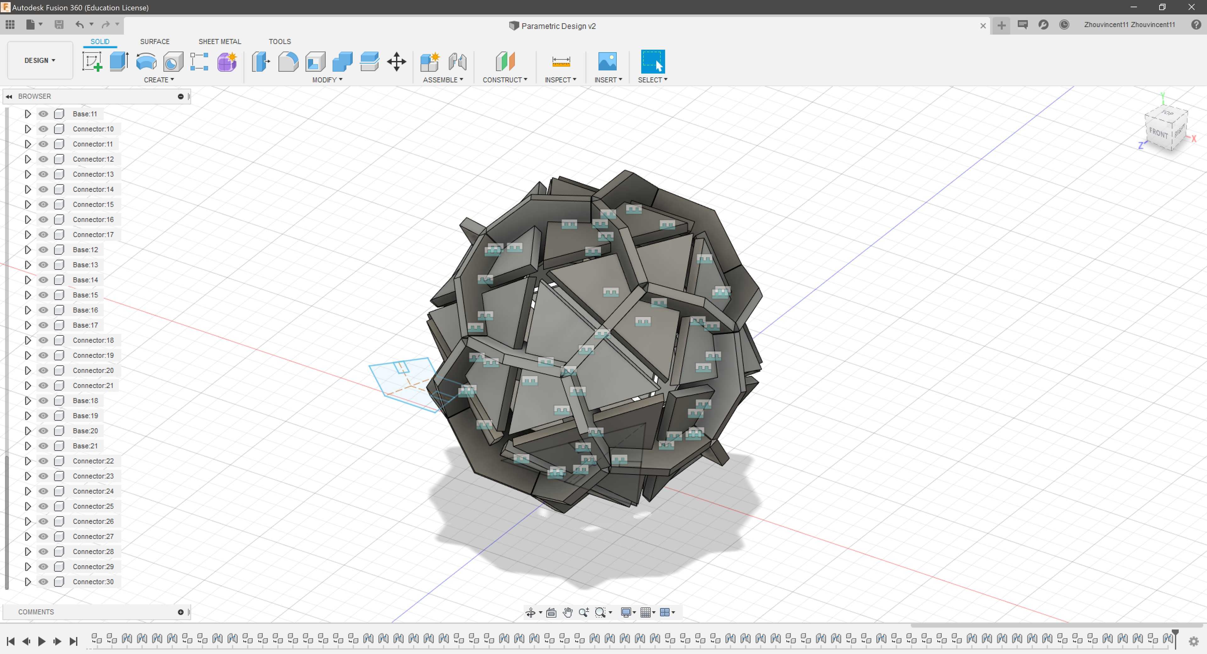
The corrected assembly worked perfectly and I continued duplicating and joining pieces together until I had fully assembled the icosahedron.
To actually cut the parametric design on cardboard, I had to measure the thickness of the cardboard with calipers. The cardboard turned out to be about .153 in. thick, so I changed the parameter “cardboard_thickness” to reflect the thickness.
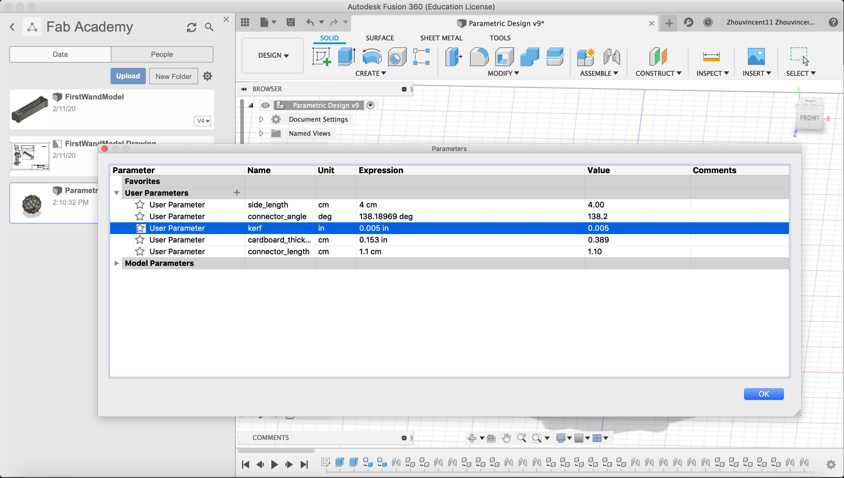
However, my brother, William, informed me that my kerf was wrong because I added the kerf value instead of subtracting the kerf value in the slot width. I changed the dimension of the slot width to “cardboard_thickness - kerf”.
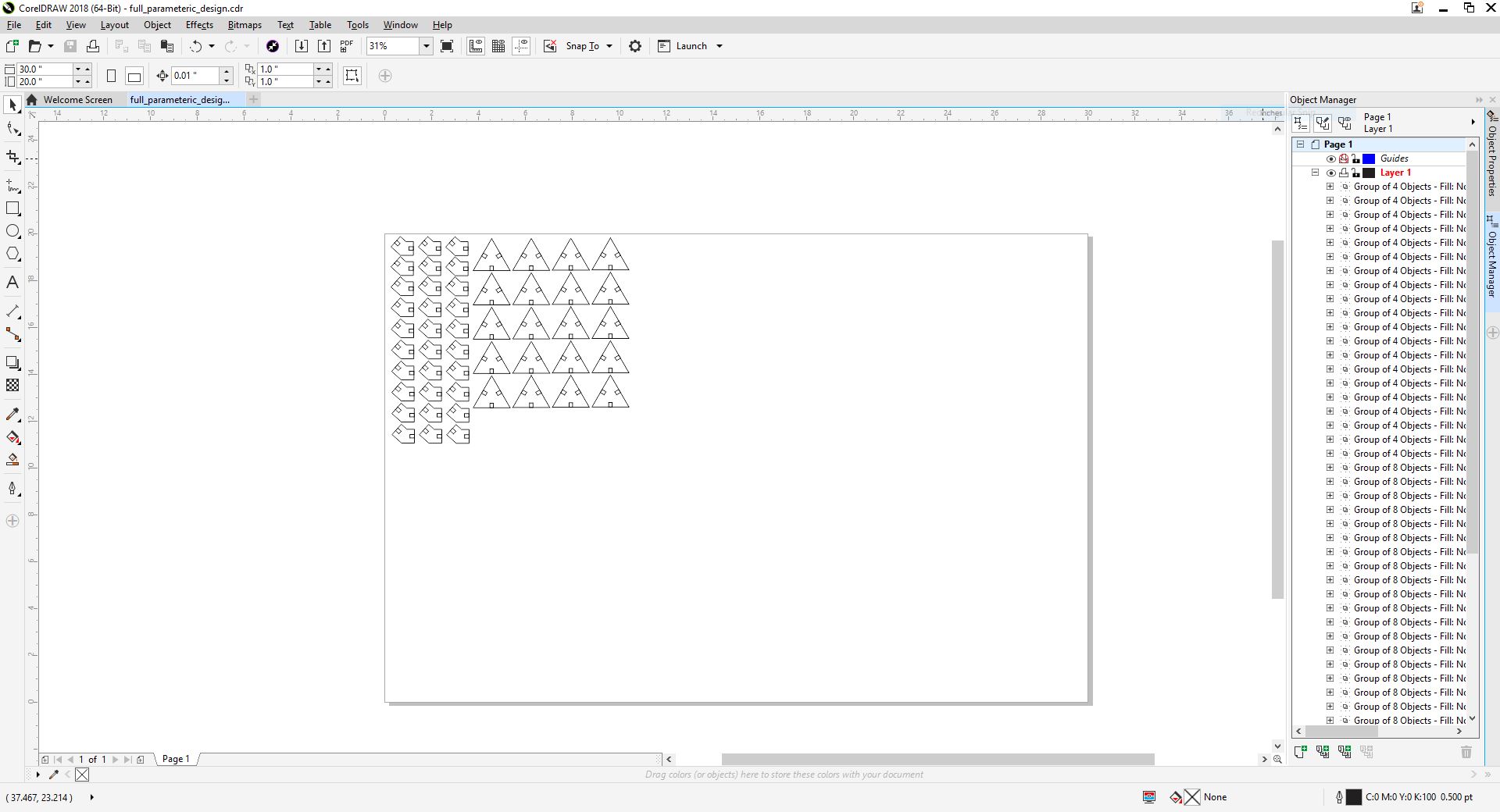
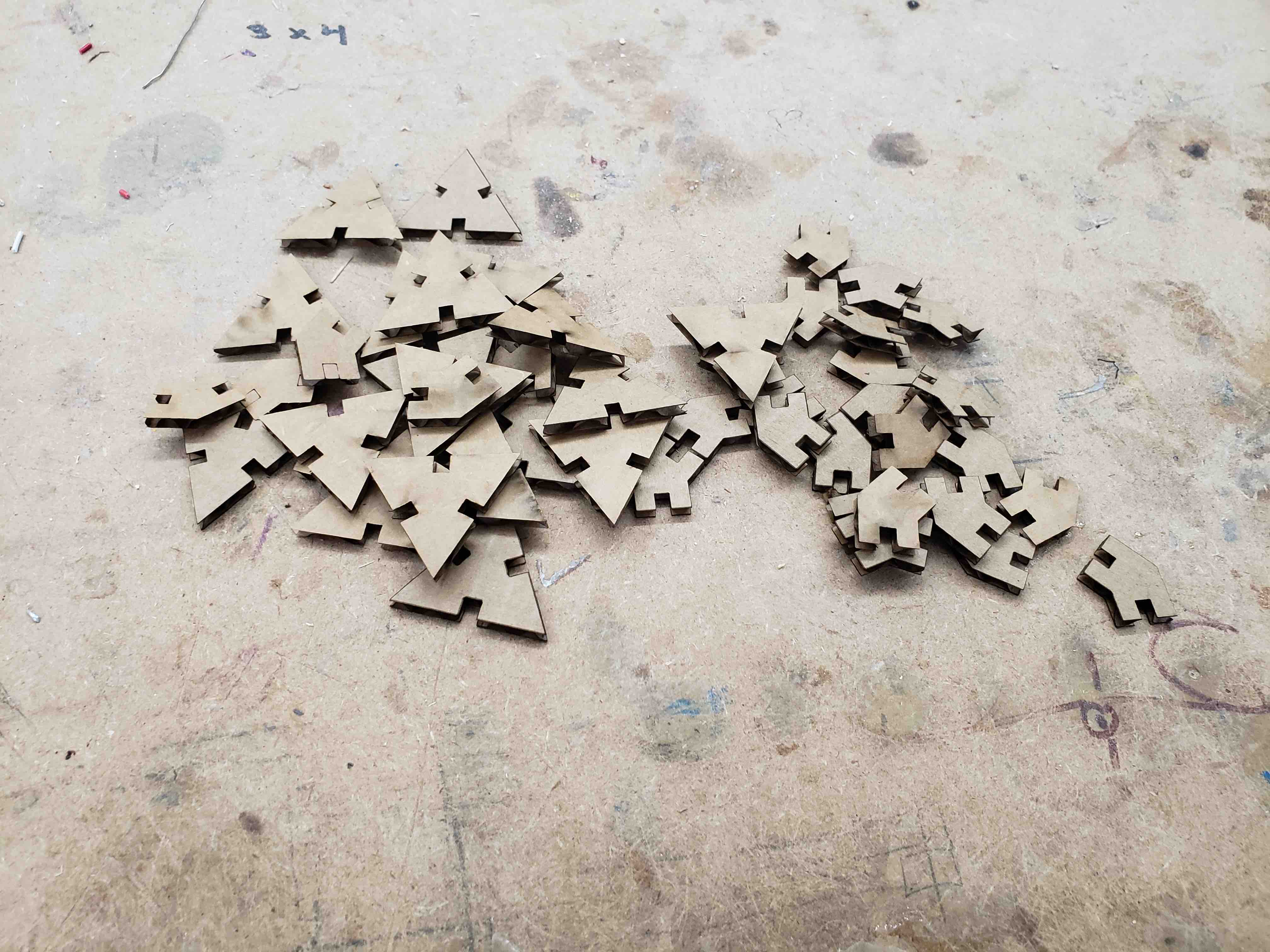
With the changes implemented, I exported the sketch as a .dxf and imported the file into CorelDraw. I decided to create a test design first to see if the dimension were correct. I only put three connectors and one face piece.
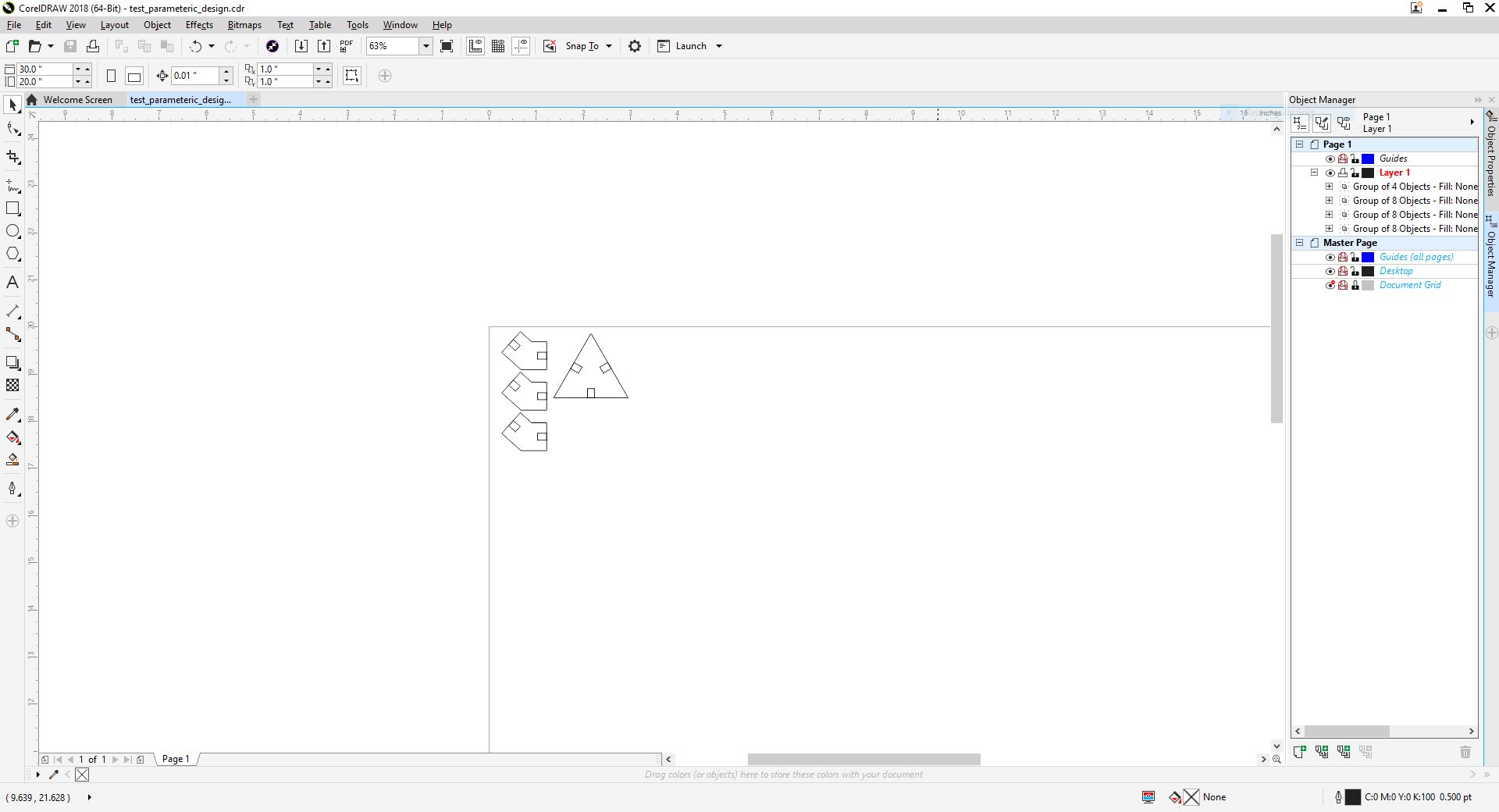
After cutting the test design out, I assembled the pieces together. The pieces fit perfectly.
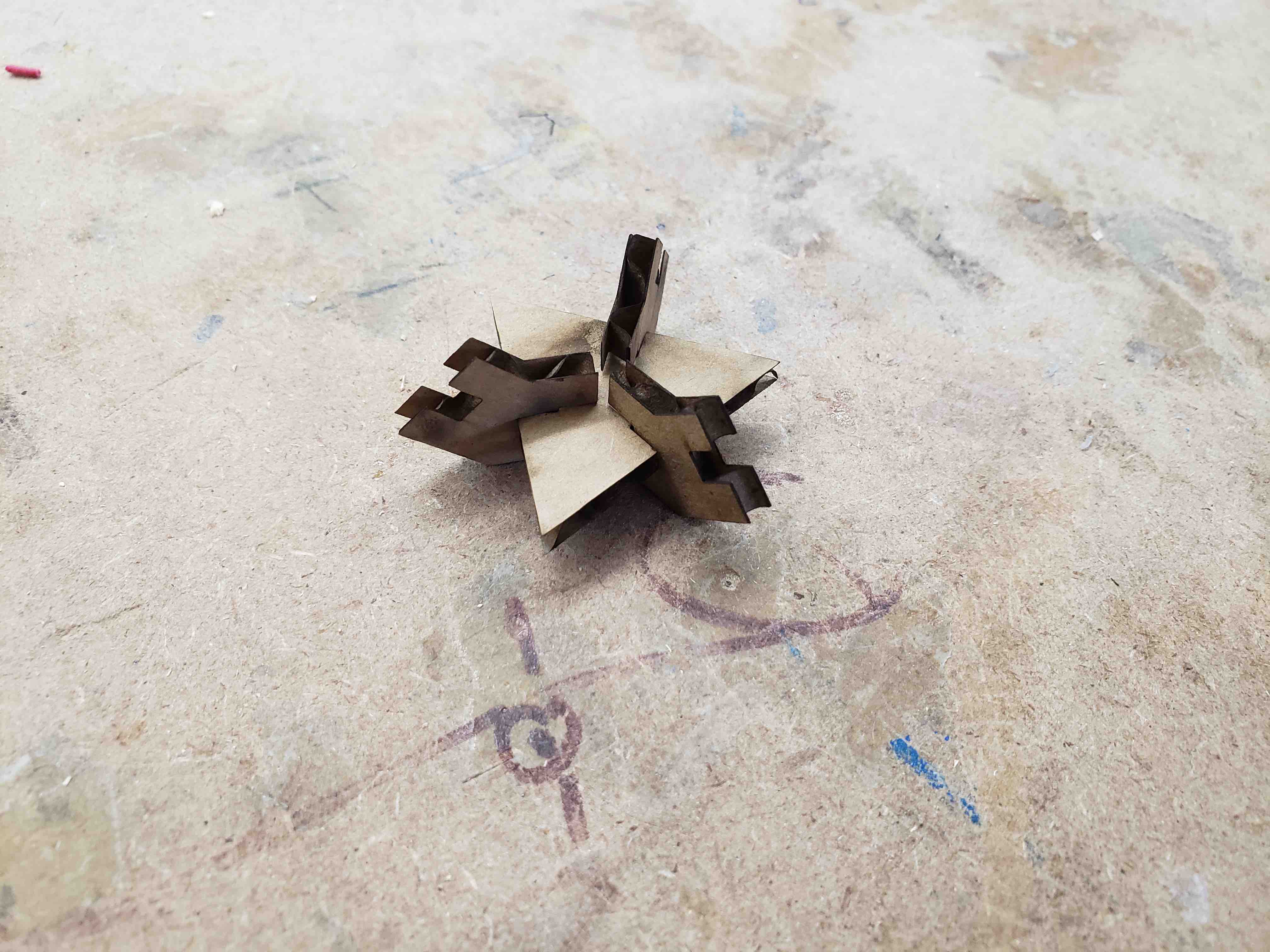
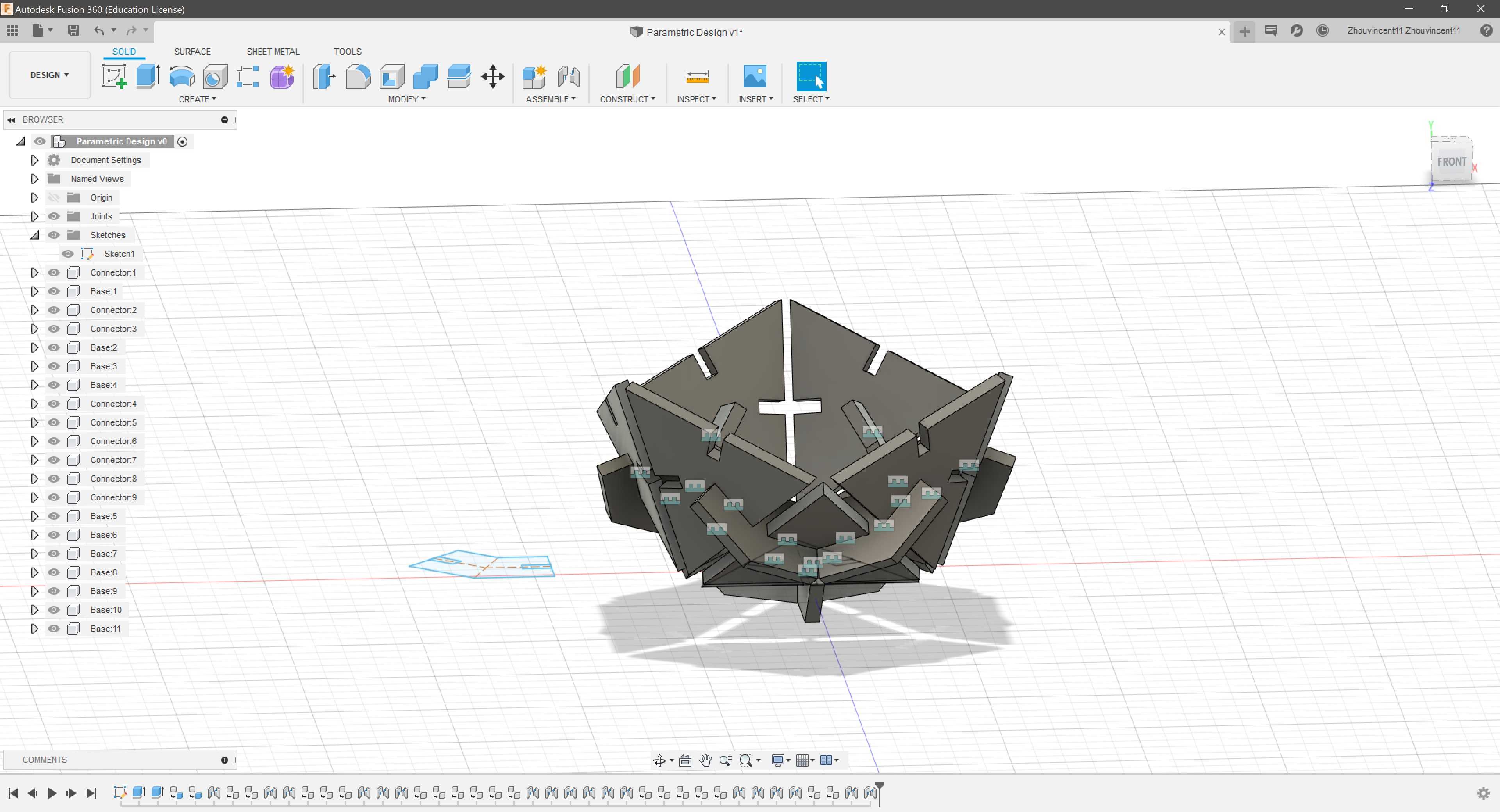
With the sucess of the test design, I cloned enough connectors and face pieces to assemble a full icosahedron. This required 30 connectors and 20 face pieces.
Assembling the icosahedron was a painstaking task as it became increasingly difficult to join connectors and face pieces as the final assembly became more crowded. However, in the end, I was able to assemble a full icosahedron.
Group Assignment
During the group assignment, I helped design the CorelDraw sketches for the laser cutter characterization. The first iteration was based off of the sketch done by Charlotte Latin Fab Academy alumni. For each laser cutting settings (Speed, Power, Freqeuency), we would change that settings and keep the other settings constant at 50%. However, William Knight, an alumni, warned us that what they did was incorrect. Neil wanted the characterization to included all possible combinations of laser cutter settings. So, I decided that we should increment each setting by 33.33% so that there would be a manageable 27 possible combinations. I envisioned the sketch to have three columns (Speed, Power, Frequency) and short laser cut lines next to each row that was cut using the corresponding settings. In addition, I decided to shorten the lines that the laser cutter cut out to decrease cut time.