9. Embedded programming
Individual Assignment:
- Read a microcontroller data sheet
- Program your board to do something, with as many different programming languages and programming environments as possible
Group Assignment:
- Compare the performance and development workflows for other architectures
C Programming
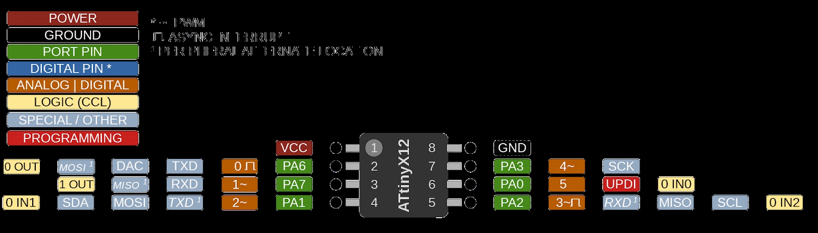
To start, I used the standard Arduino functions for pinmode, reading, and setting pins. I had previous experience with Arduino libraries, so it was relatively easy. To figure out the pin numbers, I used the helpful pinout diagram provided by Mr. Rudolph. Through trial and error, I figured out that the pin numbers used for Arduino’s functions are in the boxes labeled “Analog | Digital”. This was confusing because all other documentation pointed to pin numbers being denoted by “Port Pin”.
int led_pin = 0;
int button_pin = 1;
int delay_ms = 100;

void setup() {
  pinMode(led_pin, OUTPUT);
  pinMode(button_pin, INPUT);
}

void loop() {
  if (digitalRead(button_pin)){
    digitalWrite(led_pin, HIGH);
    delay(delay_ms);
    digitalWrite(led_pin, LOW);
    delay(delay_ms);
  }
}
While using the Arduino libaries was cool and all, Neil’s code that we used in week 7 revealed that Neil used bitwise operations to set pin modes and output. According to Neil’s code, Arduino’s digitalWrite() was the slowest of all pin setting operations. VPORTA is the fastest method of setting pins.
...

#include <avr/io.h>

#define LED_AVR PIN2_bm
#define LED_ARDUINO 3

...

PORTA.DIRSET = LED_AVR;
//pinMode(LED_ARDUINO,OUTPUT); // does the same thing

...

//
// timing tests
//
// Arduino digitalWrite: 3.9 us/bit
//
digitalWrite(LED_ARDUINO,HIGH);
digitalWrite(LED_ARDUINO,LOW);
//
// port read-modify-write: 304 ns/bit
//    6 cycles at 20 MHz
//
PORTA.OUT |= LED_AVR;
PORTA.OUT &= ~LED_AVR;
//
// port bit write: 96 ns
//    2 cycles at 20 MHz
//
PORTA.OUTSET = LED_AVR;
PORTA.OUTCLR = LED_AVR;
//
// virtual port write: 50 ns
//    1 cycle at 20 MHz
//
VPORTA.OUT |= LED_AVR;
VPORTA.OUT &= ~LED_AVR;
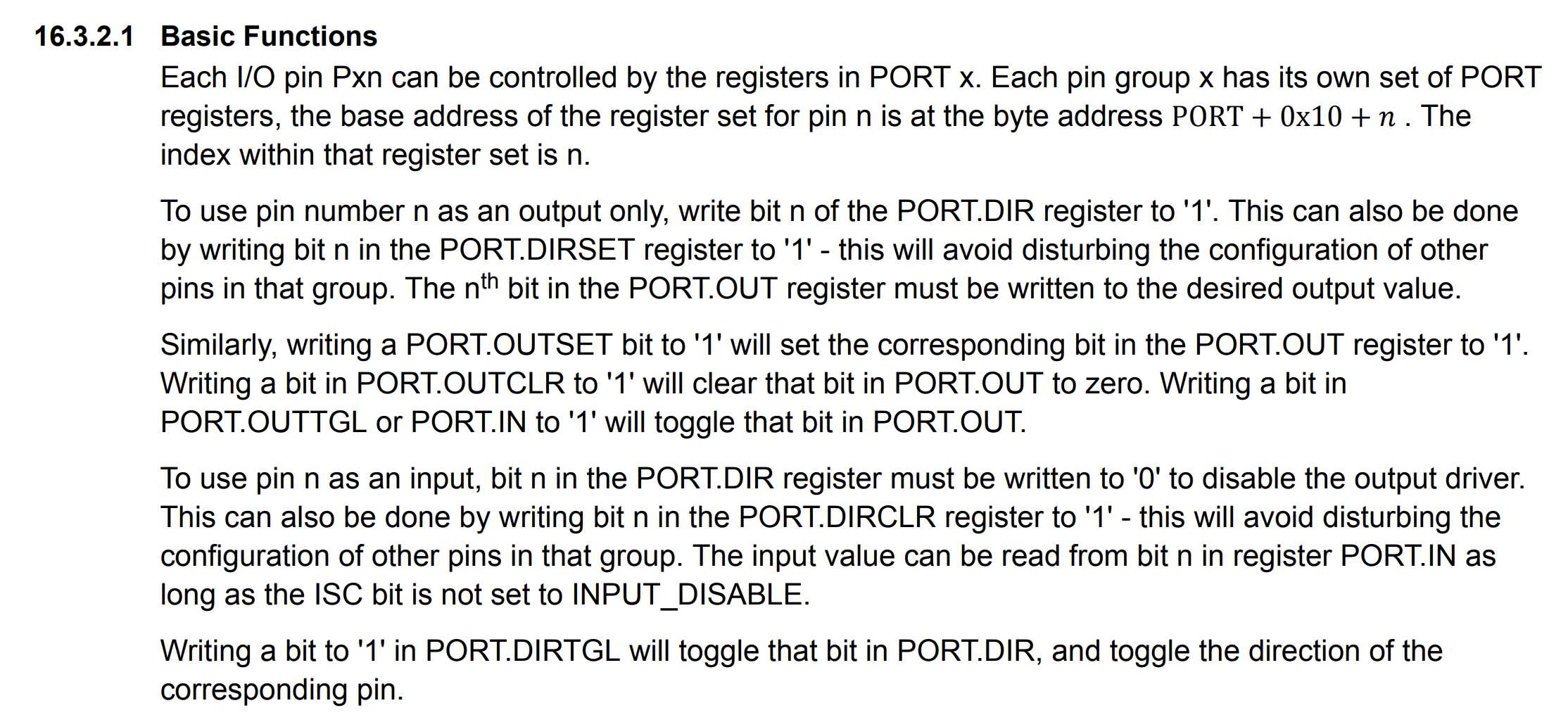
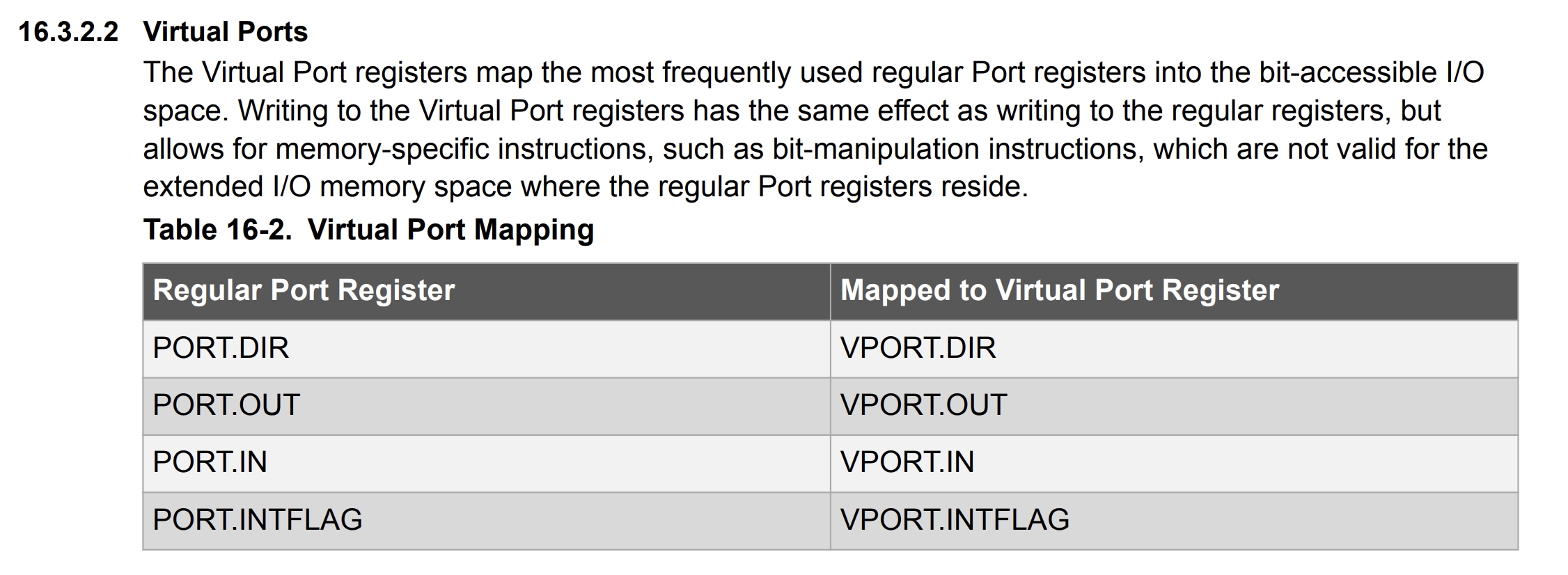
Looking at the “16. PORT - I/O Pin Configuration” section of the datasheet clarifies the use of bitwise operations. PORTA is a register in which the nth bit controls the nth pin. Therefore, in order to modify or read the nth bit, shift 1 by n to obtain the bit mask. Using DIRSET and DIRCLR is recommended as it avoids disturbing the configruations of other pins since only the bits set to 1 are set or cleared. Here, the pin numbers used for bitwise operations are in the boxes labeled “Port Pin”.
#define F_CPU 20000000
#include <avr/io.h>

void setup() {
  PORTA.DIRCLR |= (1 << 7); //DIRCLR must come first
  PORTA.DIRSET |= (1 << 6);
}

void loop() {
  if (VPORTA.IN & (1 << 7)) {
    VPORTA.OUT |= (1 << 6);
    delay(500);
    VPORTA.OUT &= ~(1 << 6);
    delay(500);
  }
}
However, bitwise operations make code less readable, so I looked for a more optimal solution. When looking at Will Knights’s page, I came across C macros that I had completely forgotten about. I decided to create my own custom macros.
#define setInputPin(pin) PORTA.DIRCLR |= (1 << pin)
#define setOutputPin(pin) PORTA.DIRSET |= (1 << pin)
#define setPinHigh(pin) VPORTA.OUT |= (1 << pin)
#define setPinLow(pin) VPORTA.OUT &= ~(1 << pin)
#define readPin(pin) VPORTA.IN & (1 << pin)
I also replaced the Arduino delay functions with Avr library delay functions.
#define F_CPU 20000000
#include <avr/io.h>
#include <avr/delay.h>

#define setInputPin(pin) PORTA.DIRCLR |= (1 << pin)
#define setOutputPin(pin) PORTA.DIRSET |= (1 << pin)
#define setPinHigh(pin) VPORTA.OUT |= (1 << pin)
#define setPinLow(pin) VPORTA.OUT &= ~(1 << pin)
#define readPin(pin) VPORTA.IN & (1 << pin)

#define led_pin 6
#define button_pin 7
#define delay_ms 500
void setup() {
  setInputPin(button_pin);
  setOutputPin(led_pin);
}

void loop() {
  if (readPin(button_pin)) {
    setPinHigh(led_pin);
    _delay_ms(delay_ms);
    setPinLow(led_pin);
    _delay_ms(delay_ms);
  }
}
Arduino
The UPDI programmer that I milled and soldered stopped working during the coronavirus outbreak, so I had to make do with an arduino. I connected a 10µF capcitor from the reset pin to ground and pin 6 to the UPDI pin of the board with a 5k resistor. Then, I uploaded the JTAG2UPDI sketch to the Arduino
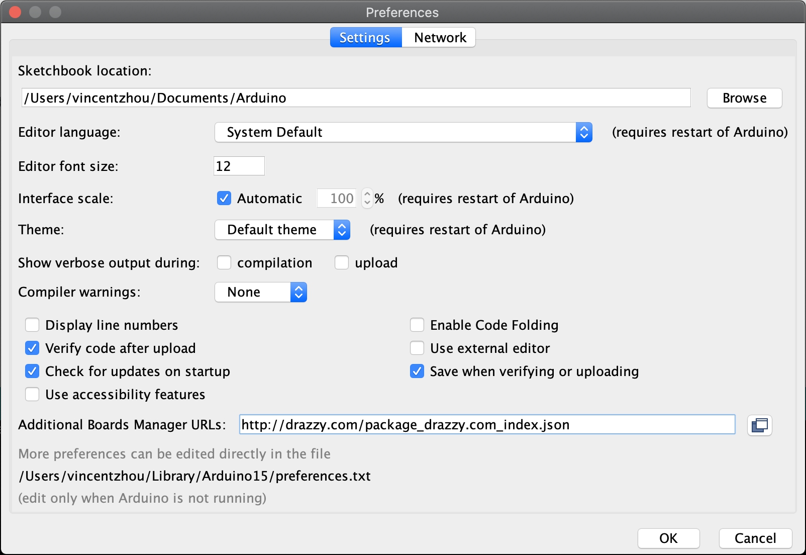
In order to setup my Arduino IDE, I used this guide from week 7.
First, I added the URL of the Board Manager in the preference pane. This allows third-party boards to be intalled in the board manager.
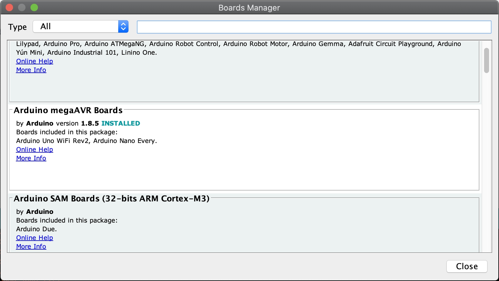
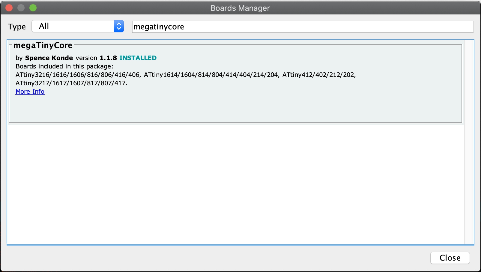
Next, in the board manager, I installed “MegaTinyCore” and “Mega AVR Boards”.
Then, in the “Tools” tab, I set the board to ATTiny412, programmer to jtag2updi, and port to the programmer port.

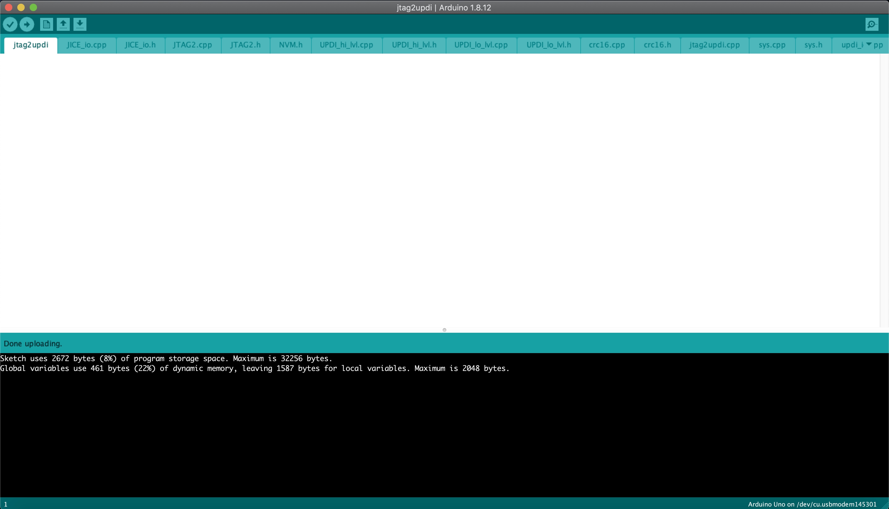
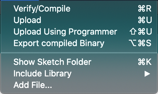
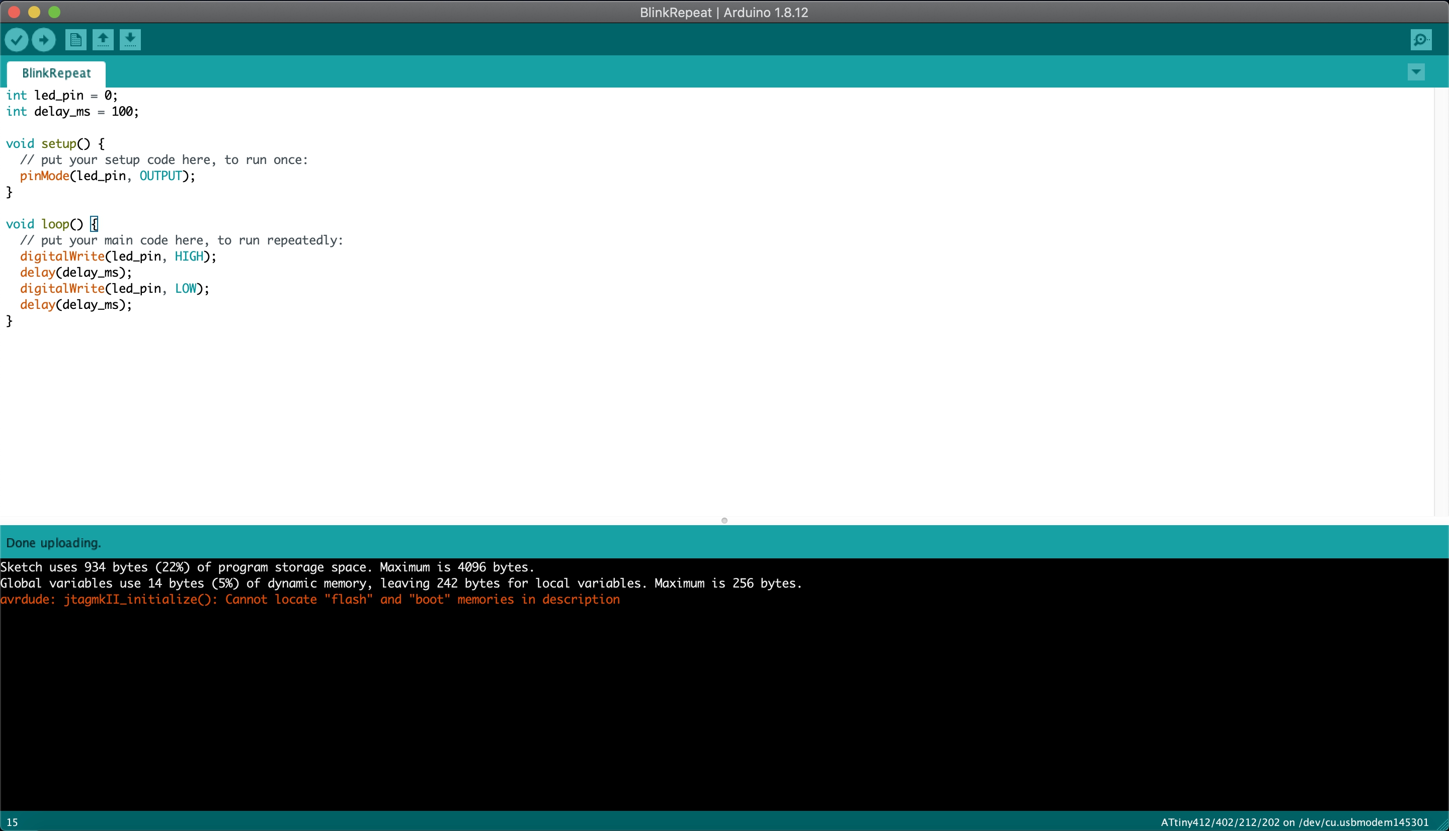
To flash the sketch to the chip, in the “Sketch” tab, I clicked “Upload through programmer”.
The console spits out an error when the flashing is done, but it is normal.
Atmel Studio
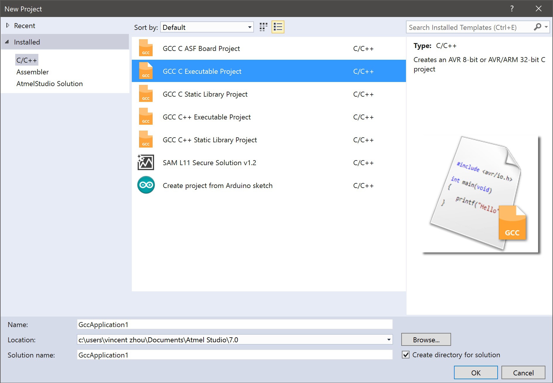
I also tried Atmel Studio to run the code. After installing Atmel Studio, I selected a new project and selected the “GCC C Exectuable Project” option.
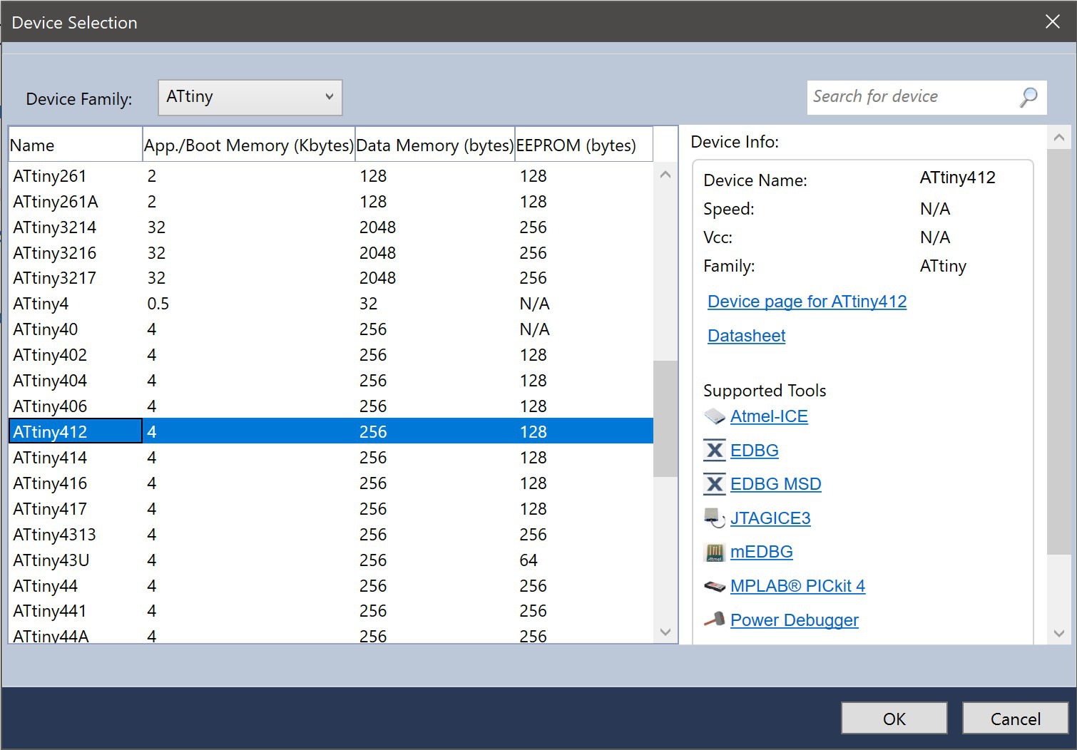
Then, I selected the ATTiny412 as my device. I filtered the options by the ATtiny family.
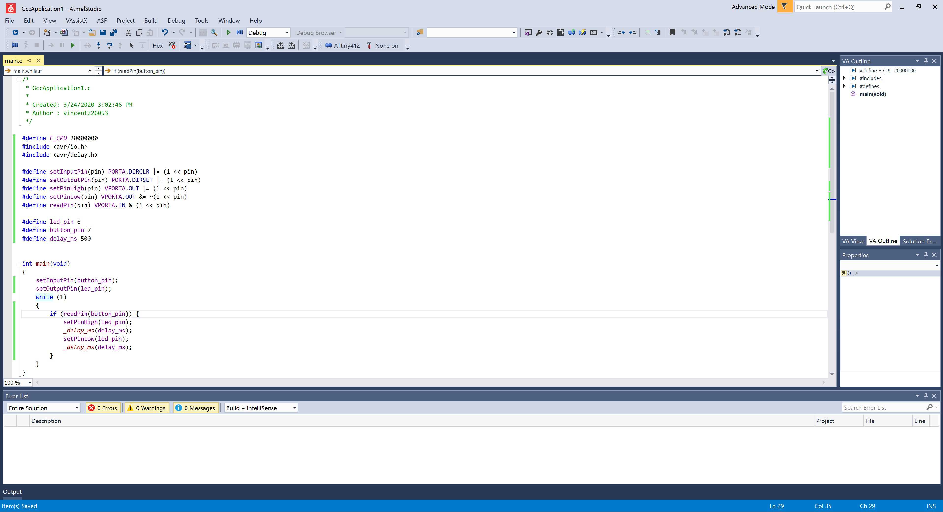
Next, I transplanted my C code into the code template. However, there was a difference in the Atmel template and the Arduino template. Atmel only has one function that runs once. Arduino has two functions: one for setup and one that loops. I had to place the setup code in front of the while loop and the loop code inside the while loop.
#define F_CPU 20000000
#include <avr/io.h>
#include <avr/delay.h>

#define setInputPin(pin) PORTA.DIRCLR |= (1 << pin)
#define setOutputPin(pin) PORTA.DIRSET |= (1 << pin)
#define setPinHigh(pin) VPORTA.OUT |= (1 << pin)
#define setPinLow(pin) VPORTA.OUT &= ~(1 << pin)
#define readPin(pin) VPORTA.IN & (1 << pin)

#define led_pin 6
#define button_pin 7
#define delay_ms 500


int main(void)
{
    setInputPin(button_pin);
    setOutputPin(led_pin);
    while (1)
    {
      if (readPin(button_pin)) {
        setPinHigh(led_pin);
        _delay_ms(delay_ms);
        setPinLow(led_pin);
        _delay_ms(delay_ms);
      }
    }
}
However, Atmel Studios was installed on my Windows Machine, while avrdude, avr-gcc, avr toolchain and other prerequisiites were installed on my MacBook. To remedy this problem, I navigated into the Atmel project and extracted the compiled hex file. I transfered the file over to my MacBook to use avrdude.
On Arduino, I enabled verbose upload in Preferences and looked at the avrdude configuration used to upload my Arduino sketch.
/Users/vincentzhou/Library/Arduino15/packages/arduino/tools/avrdude/6.3.0-arduino17/bin/avrdude -C/Users/vincentzhou/Library/Arduino15/packages/megaTinyCore/hardware/megaavr/1.1.8/avrdude.conf -v -pattiny412 -cjtag2updi -P/dev/cu.usbmodem145301 -Uflash:w:/var/folders/3h/mvbwx58x6n9b0lsxn8dbztjw0000gn/T/arduino_build_43743/LEDButtonWithMacros.ino.hex:i
I simply replaced the target hex file path with the path of the hex file compiled in Atmel Studios. In addition, I replaced the port with the port that programmer is connected to.
/Users/vincentzhou/Library/Arduino15/packages/arduino/tools/avrdude/6.3.0-arduino17/bin/avrdude -C/Users/vincentzhou/Library/Arduino15/packages/megaTinyCore/hardware/megaavr/1.1.8/avrdude.conf -v -pattiny412 -cjtag2updi -P/dev/cu.usbmodem144401 -Uflash:w:GccApplication1.hex:i
The flashing was a success, however, the delay for the blinking led was too long. The documentation of the delay.h library reveals that the library depends on F_CPU. I changed F_CPU to 1/10 of the original frequency and, suprisingly, the delay became correct. It also worked the reverse way: original frequency, 1/10 of the delay. This is a really strange quirk.
This experience is a crucial stepping stone toward the development of my project because understanding the core functionality of the AVR library and experiencing the workflow will enhance my programming. Unlike arduino, the AVR library is more unforgiving and has a lot less documentation requiring a deep understanding in C++. However, the AVR library is also more powerful as seen by the massive speed and efficiency in using the AVR library to manipulate pin ouput and input. Given the compact nature of my project and the potentially complex code requirements, the powerful and efficiency AVR library will prove to be useful.
Here is the video of the boarding working: