3. Computer Aided design
Assignment:
- Model (raster, vector, 2D, 3D, render, animate, simulate, …) a possible final project,
- Compress your images and videos, and post it on your class page
Fusion 360
I started to design a premilinary model of my wand with a rough idea of the size of the interior. I began first with Autodesk Fusion 360, a program that I had used extensively previously.
Design
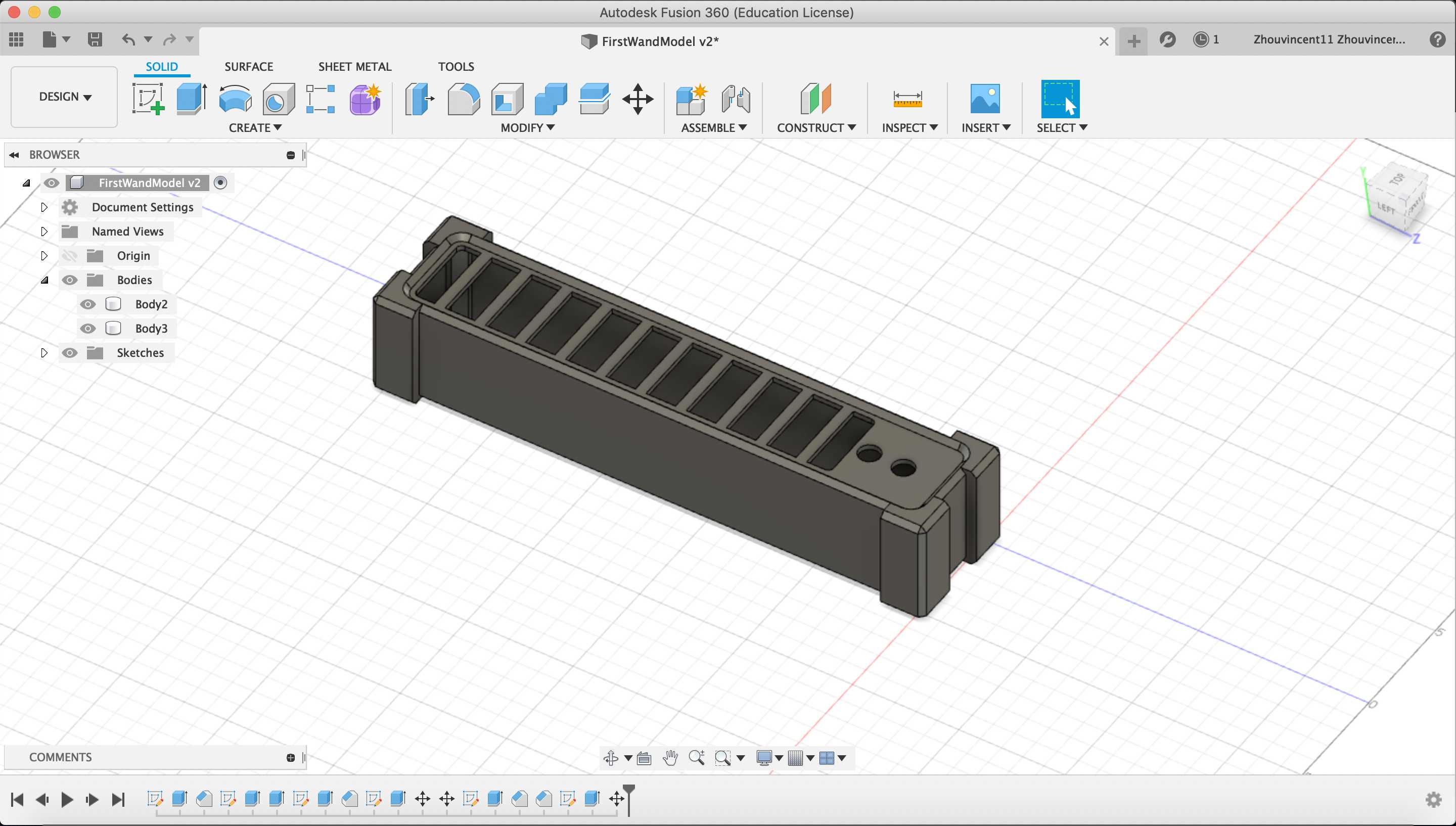
First I created a sketch on the XZ plane and created a rectangle to represent the main body of the wand. Using the dimensioning tool, I defined the rectangle to be 5 cm x 25 cm. To replace the boring corners, I added some edges onto the rectangle and dimensioned the edges to be .5 cm wide and extend 1.5 cm from the body. I only added edges on one side of the body because I planed to mirror one side of the body to the other side.
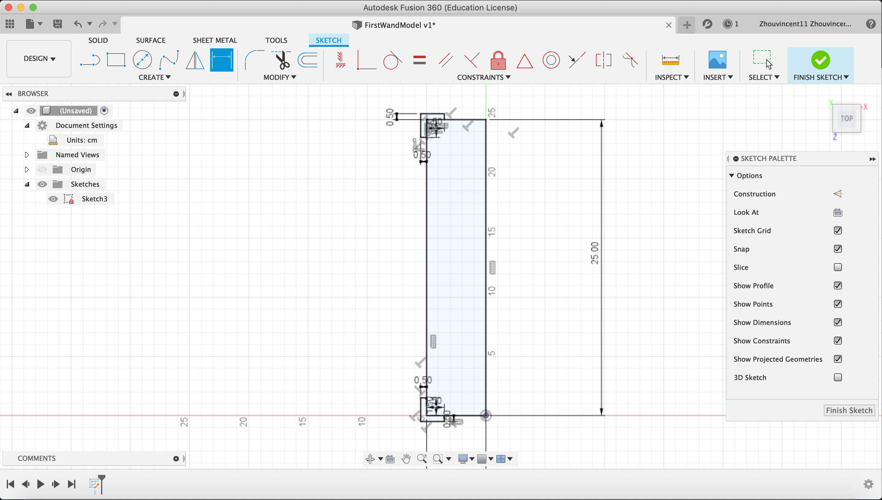
To do so, I created a line that bisects the body vertically and converted that line to a construction line. This line will act as the line to mirror the edges across.
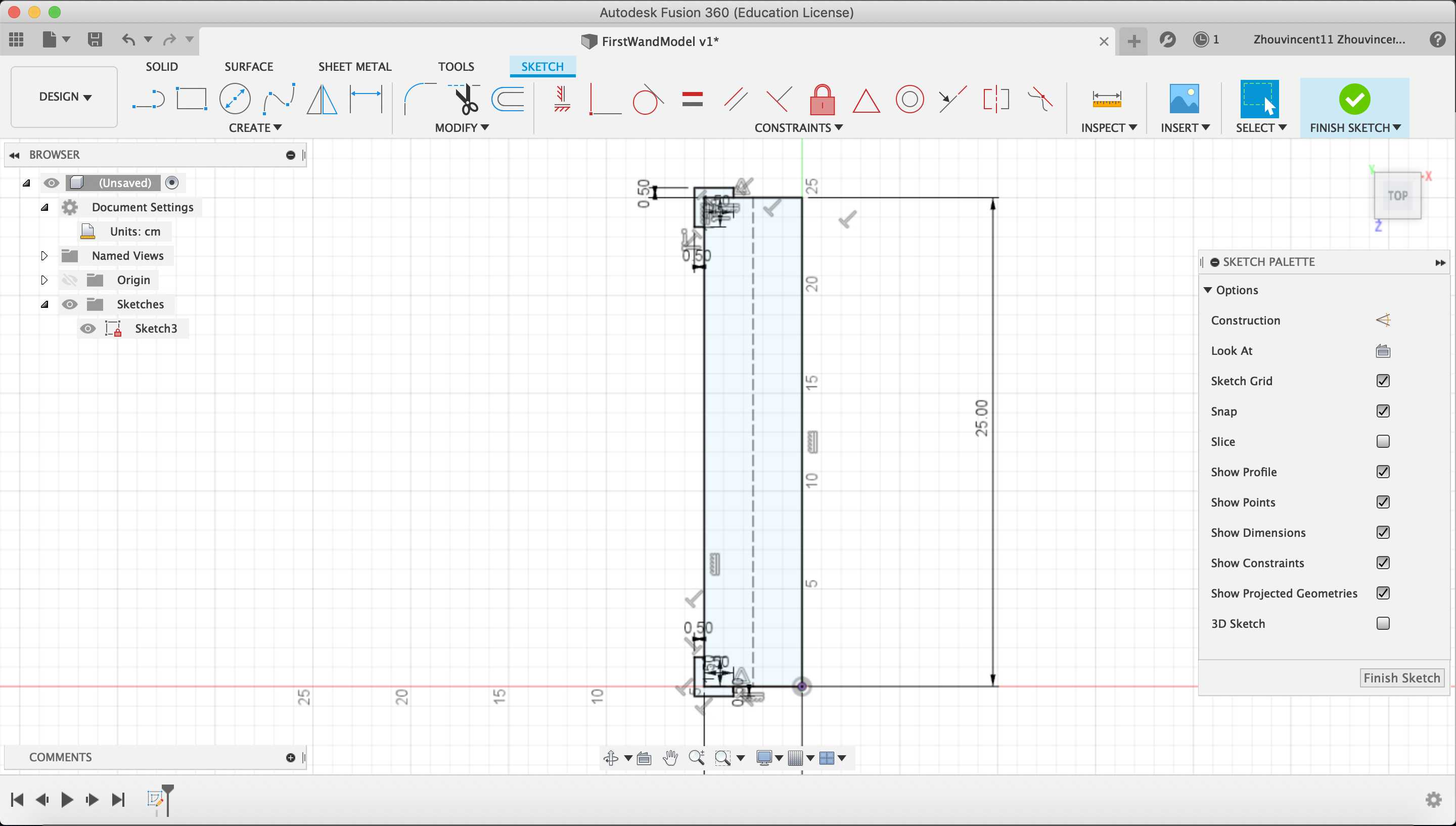
Then, I selected the “Mirror” tool and designated the two edges as the objects to mirror and designated the construction line as the mirror line.
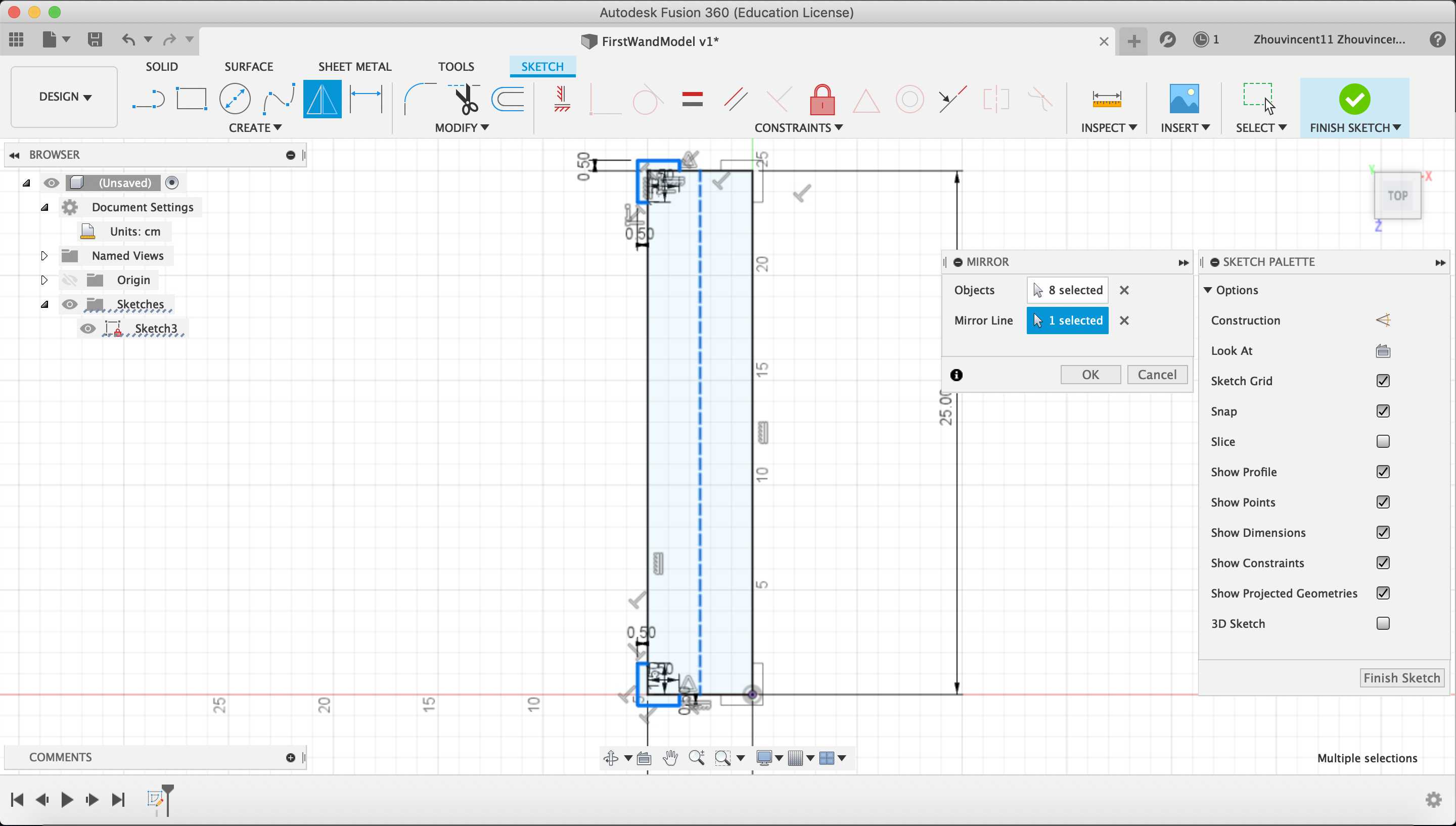
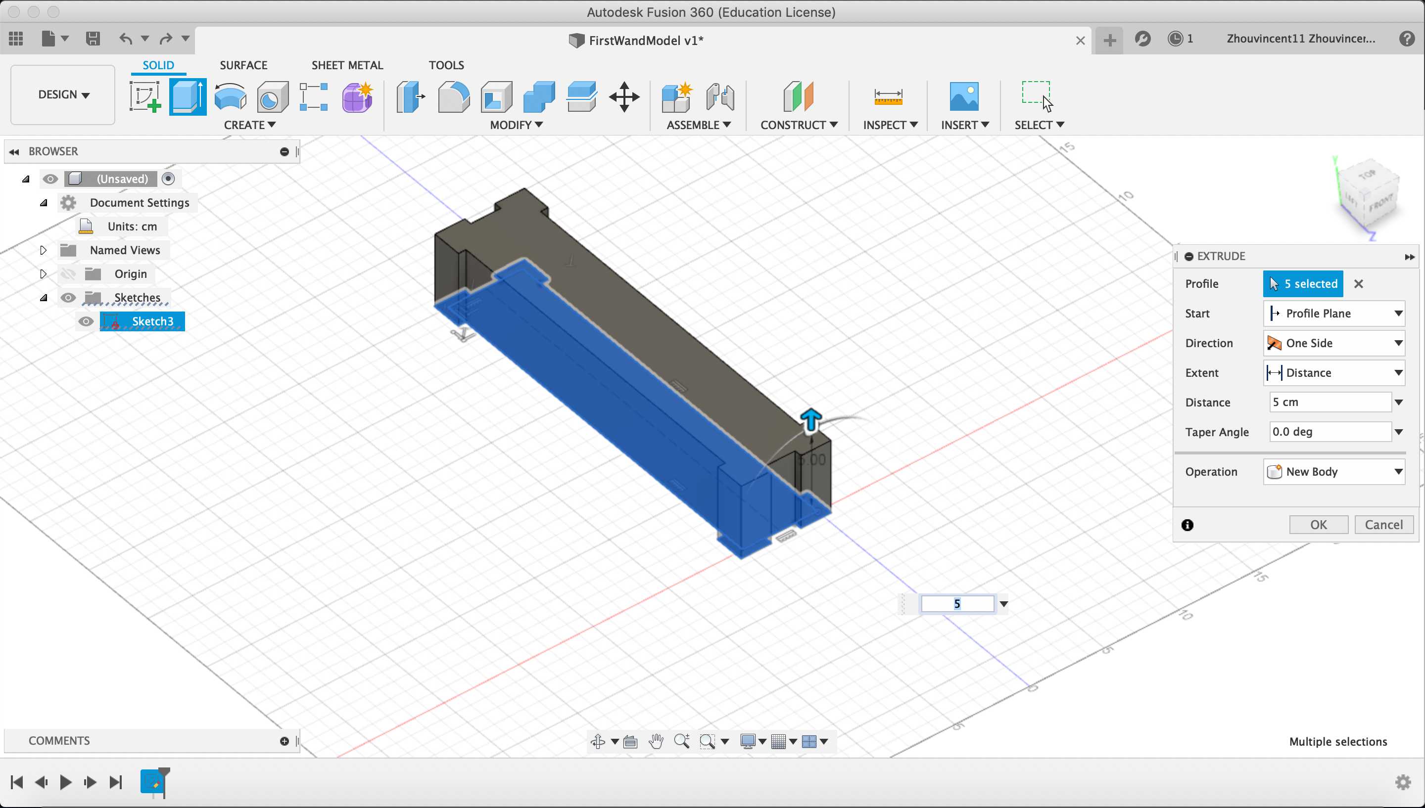
With the 2D sketch of the main body completed, I used the “Extrude” tool to extrude the sketch up by 5 cm.
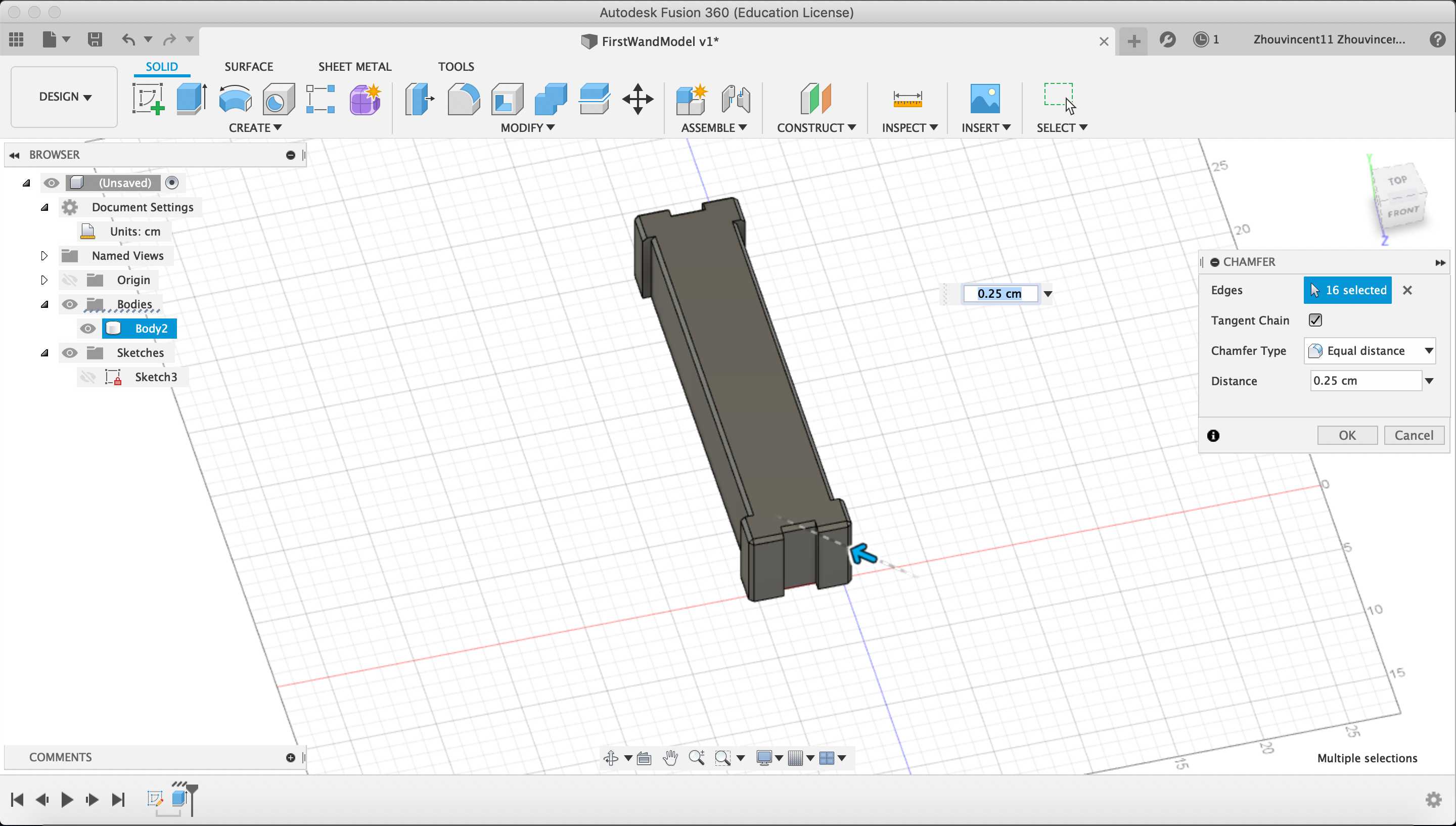
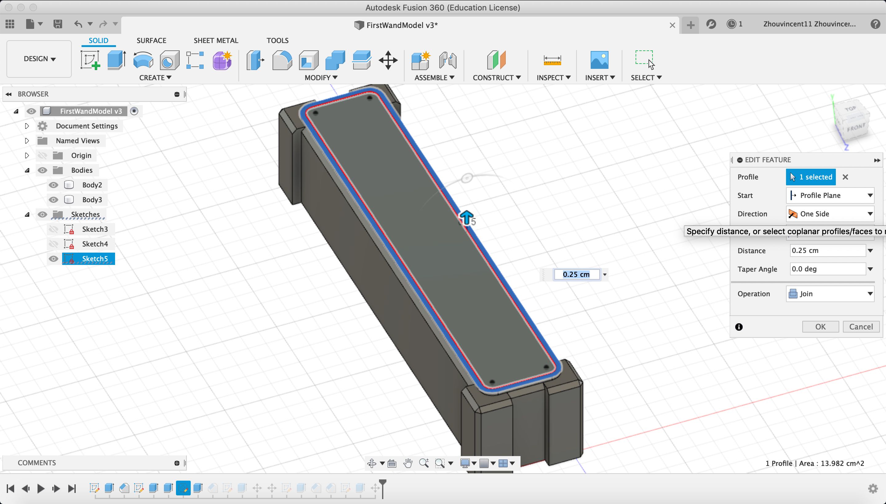
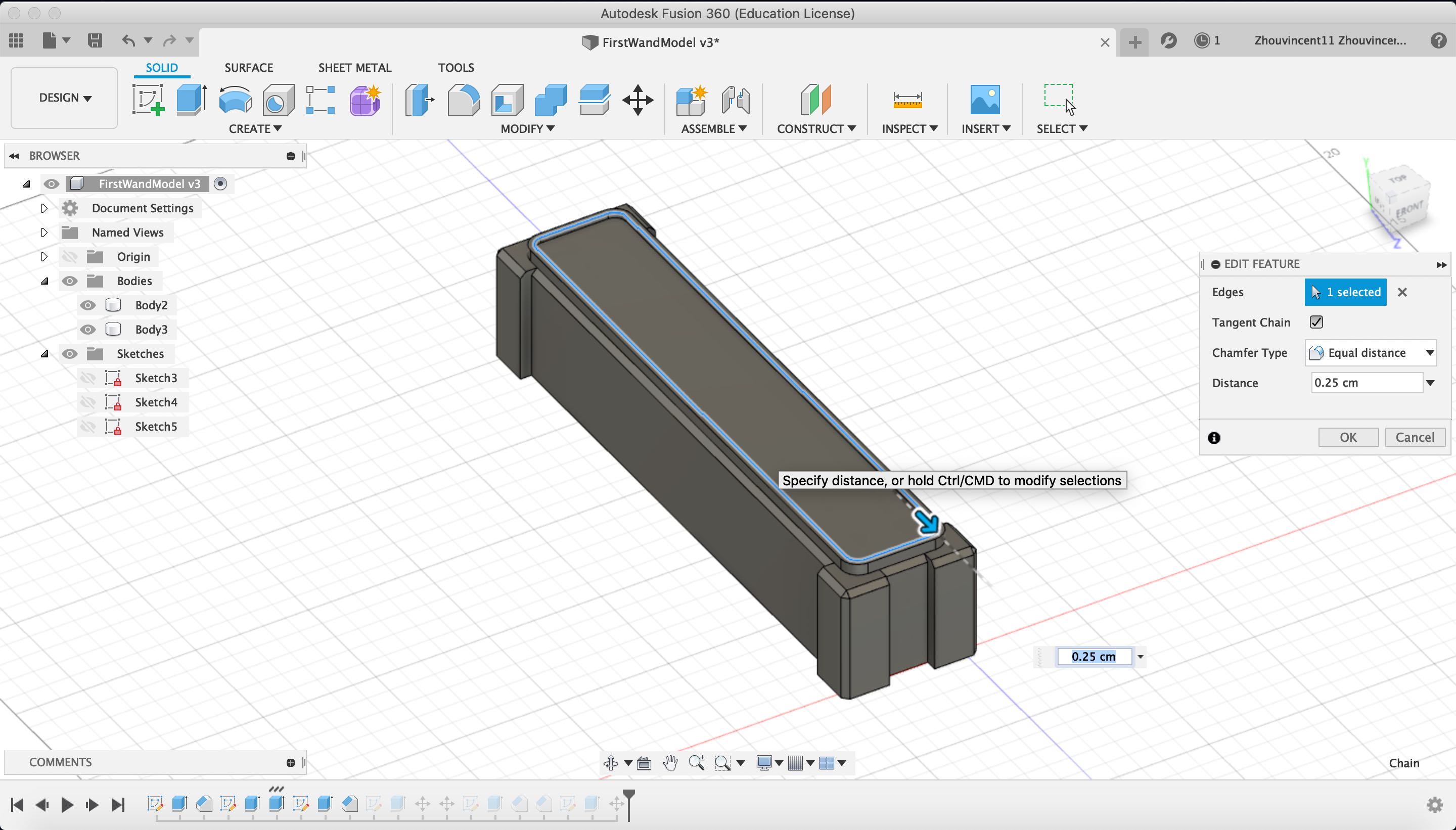
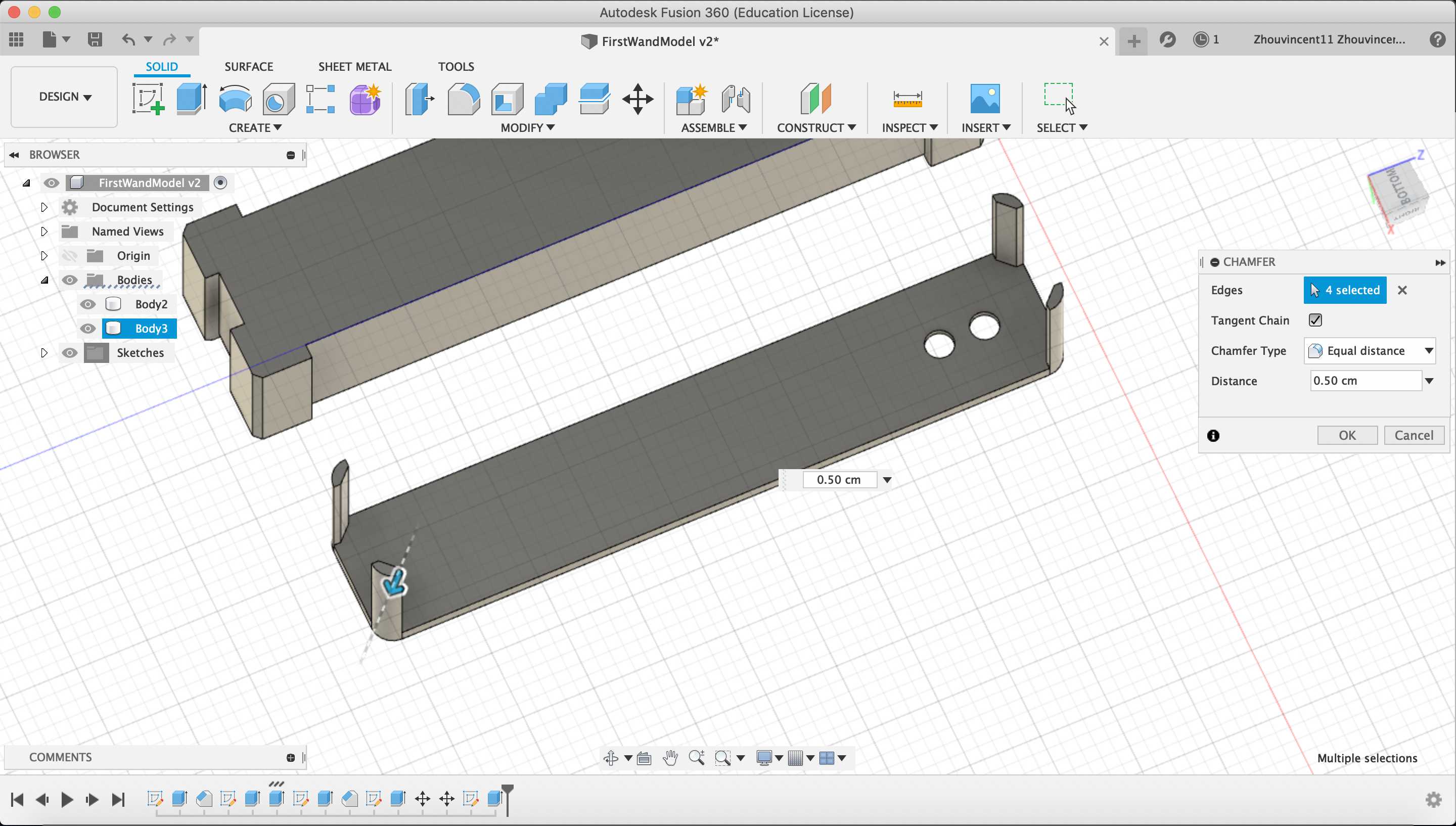
The round off the corners of the body and provide an industrial look, I used the “Chamfer” tool to chamfer the top and side edges of the body with a distance of .25 cm.
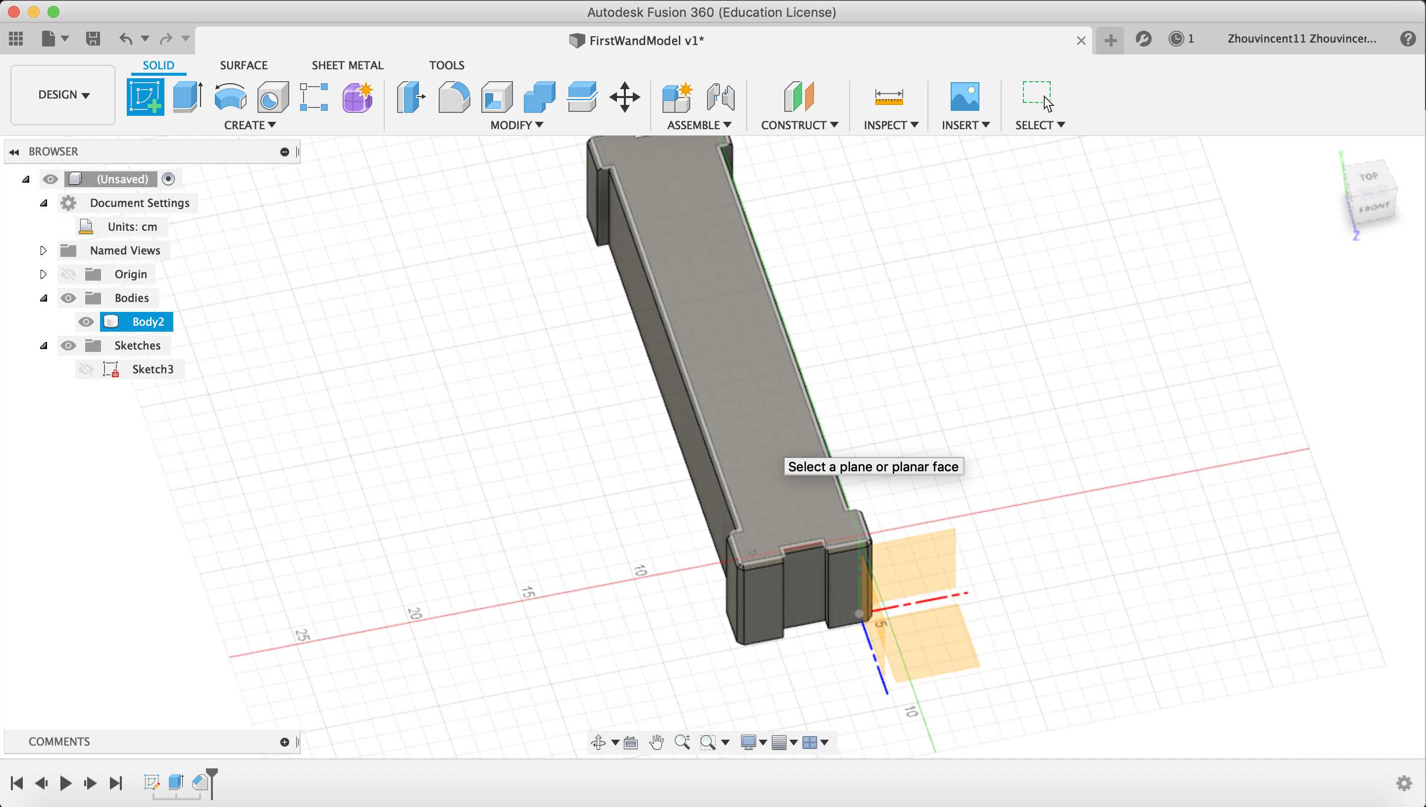
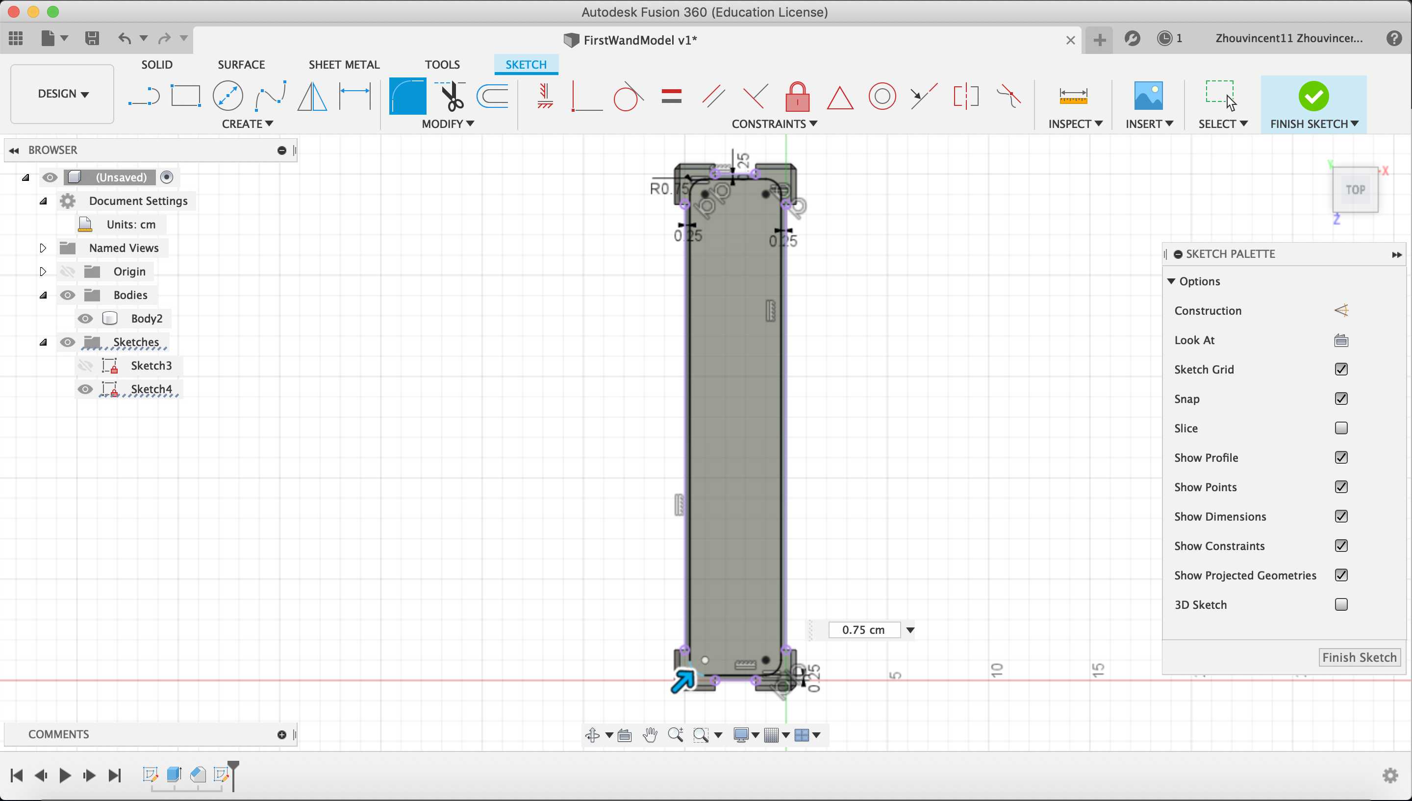
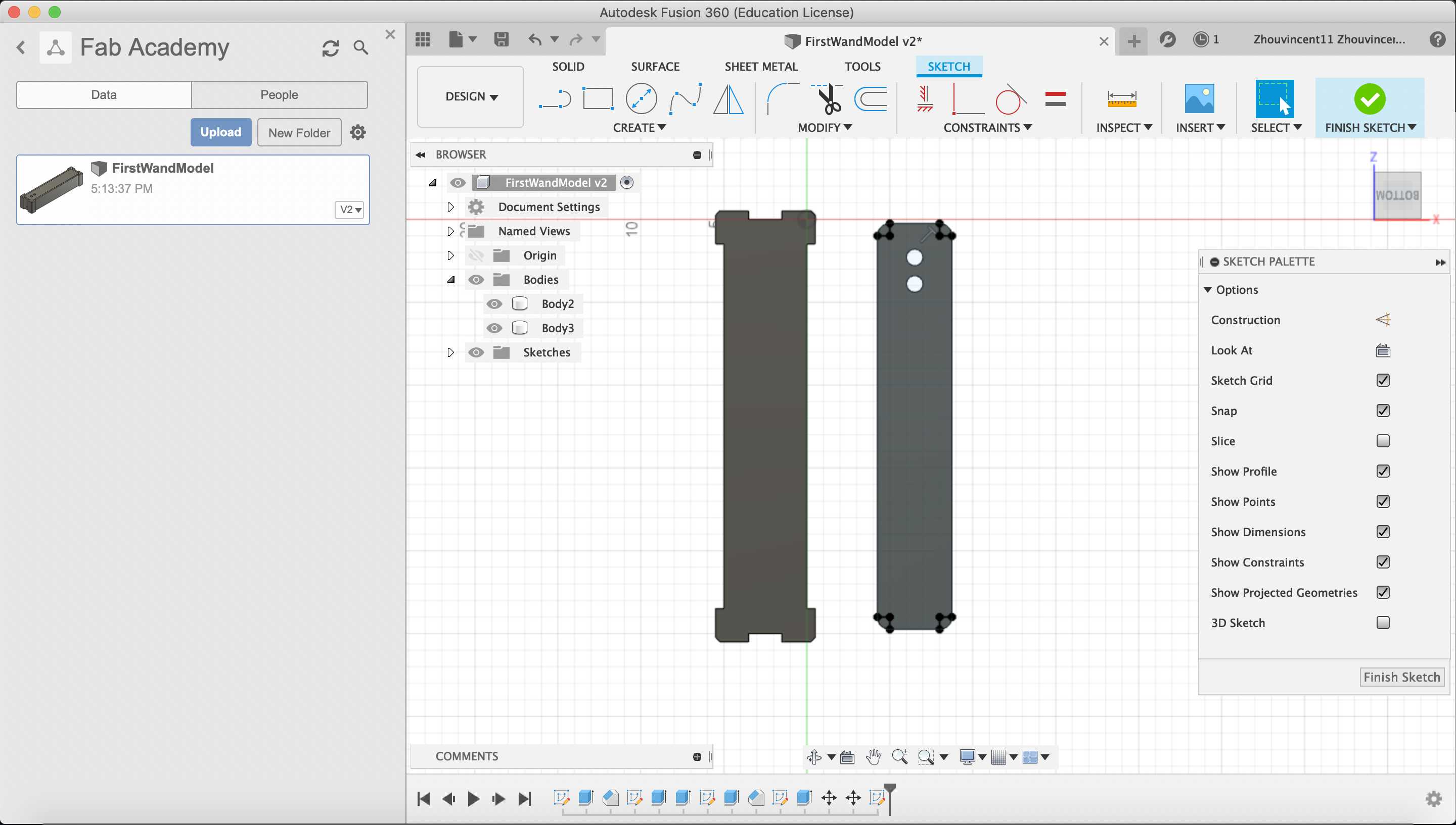
Next, I created a sketch on top the of the body to hollow out the body.
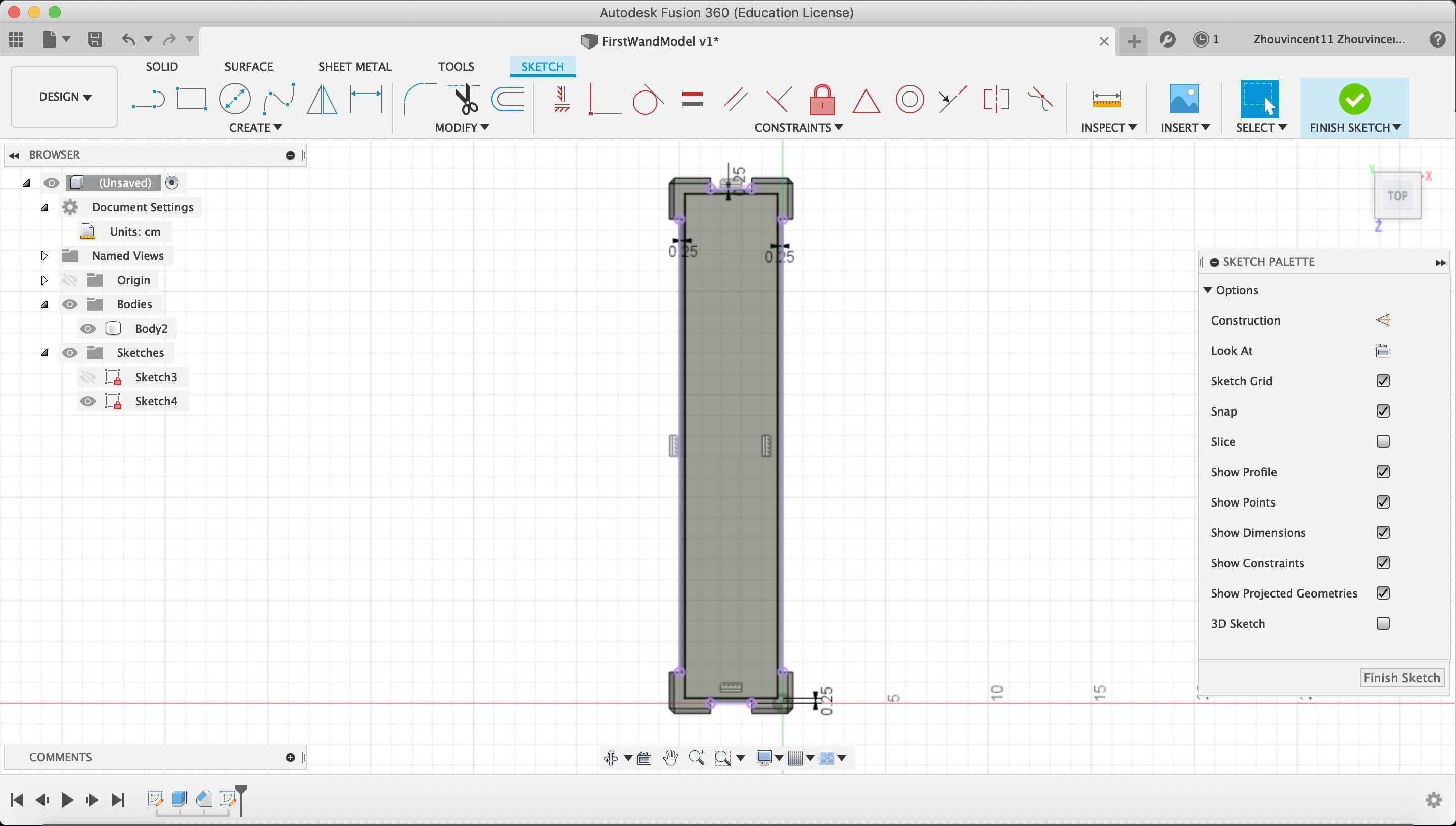
I projected the edges of the body by selecting the “Project” tool and designating the lines on the body that I wanted to reference. I dimensioned a rectangle to be .25 cm inside the projected lines.
I rounded the corners of the rectangle by using “Fillet” tool and designating the corners of the rectangle with a radius of .75 cm.
With the sketch done, I cut extruded the sketch down until about .25 cm from the XZ plane so that the body would have uniform thickness. The hole in the body will house all electronics needed in the wand.
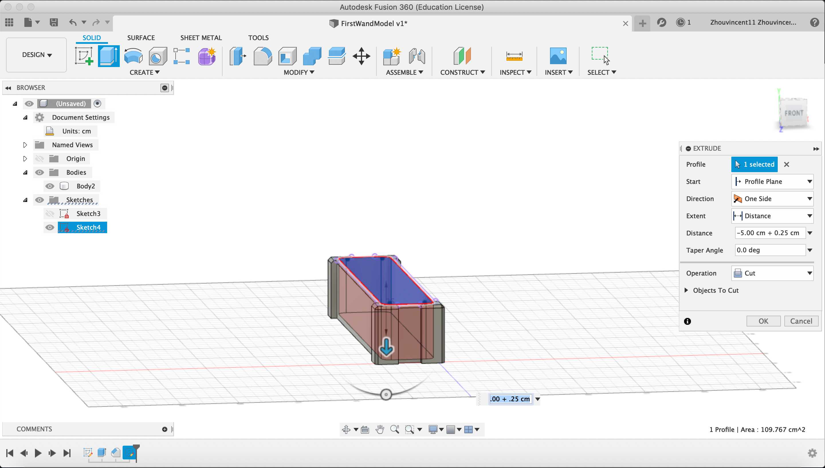
Then, I extruded the same sketch upwards by .25 cm to create a lid with the same thickness as the body.
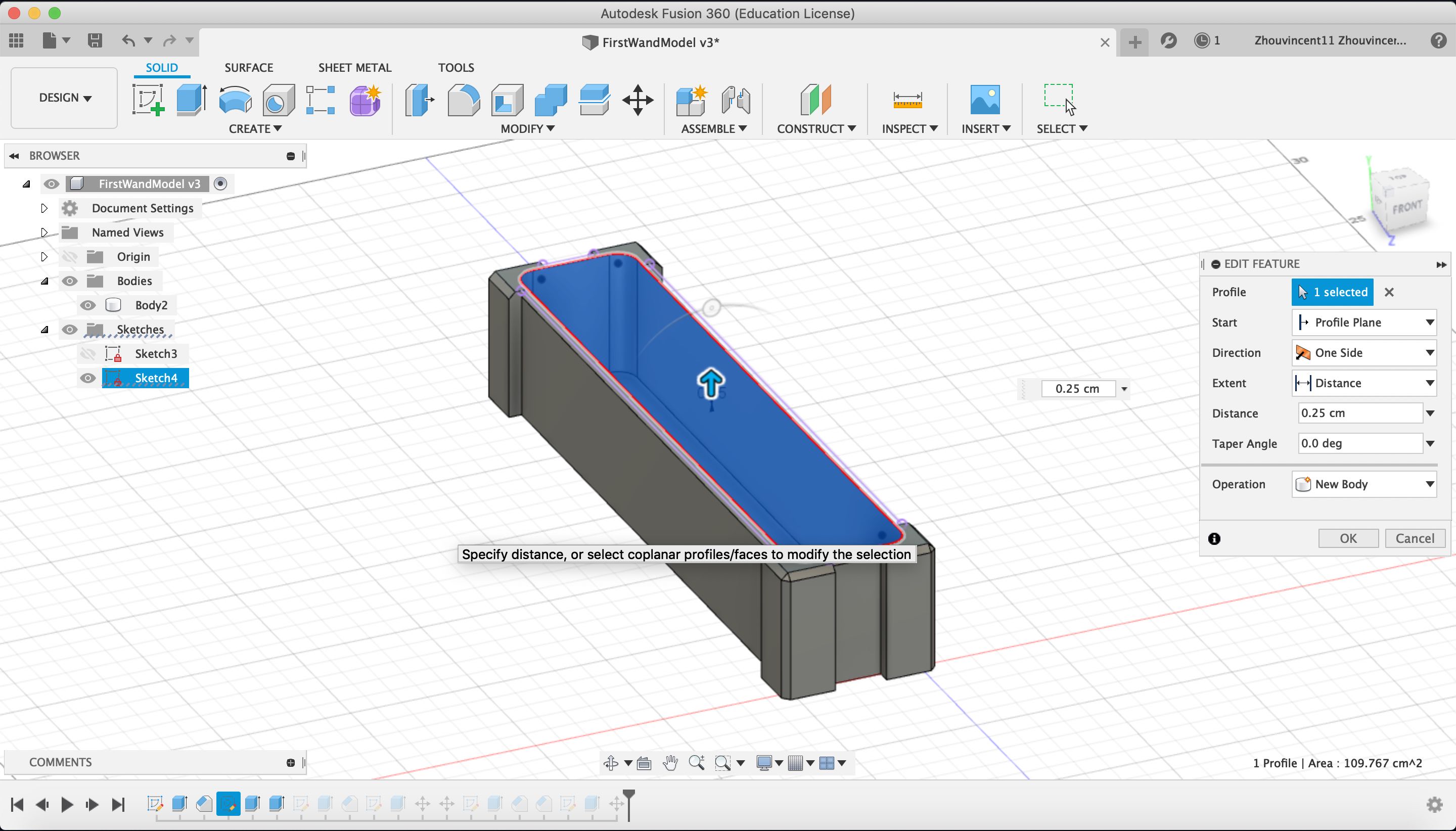
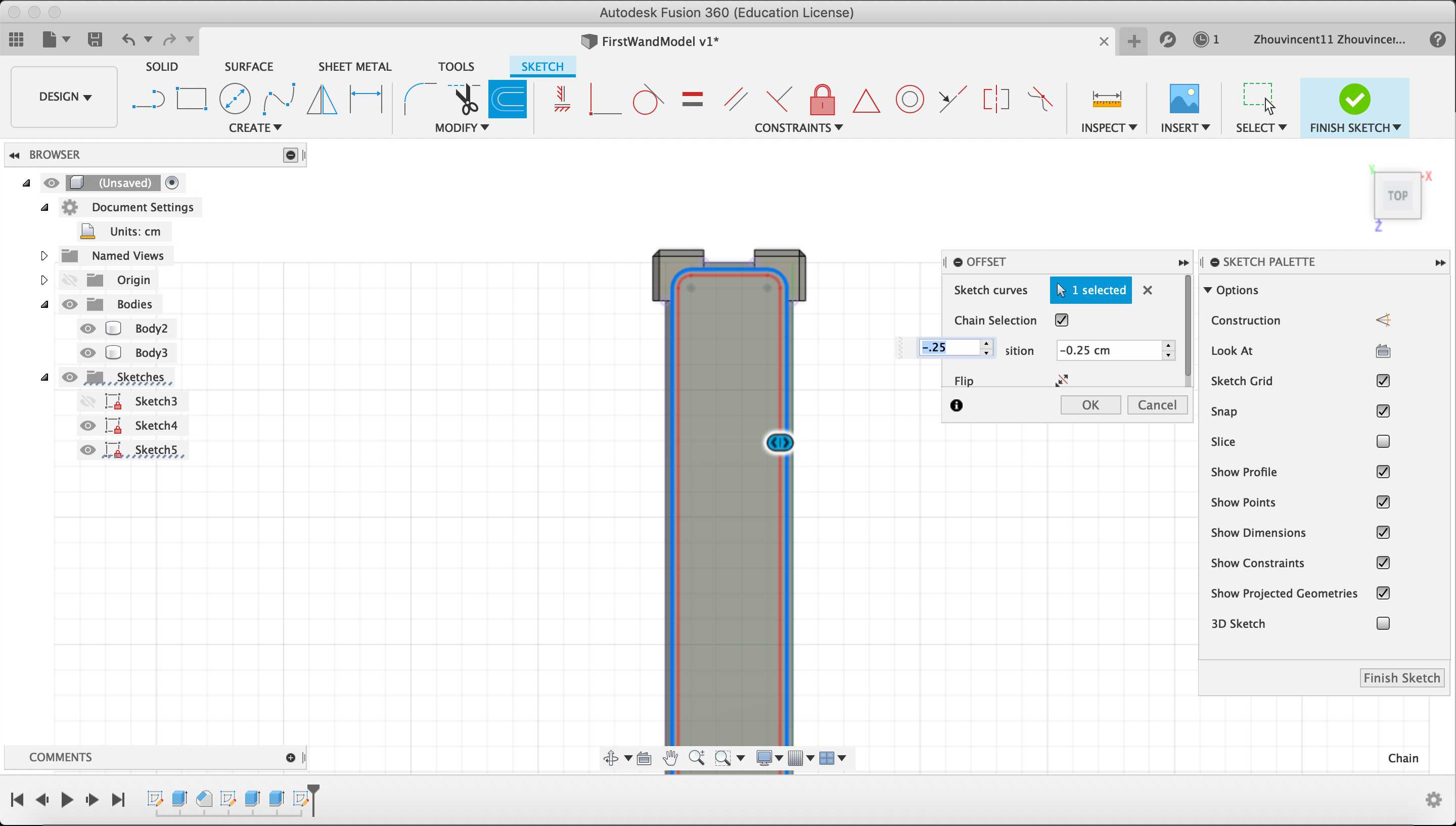
To create a varied edge to the lid, I used the “Offset” tool to create an outline .25 centimeters inside of the edge of the edge.
I extruded the region between the offset and edge of the lid up by .25 cm and then chamfered the region with a distance of .25 cm to make the lid appear depressed compared to the top of the main body.
Next, I added features onto the lid. First, I created a sketch on the lid, created two circles with a diameter of 1 cm, and cut extruded the sketch through the led. The holes will allow buttons to integrated into the wands.
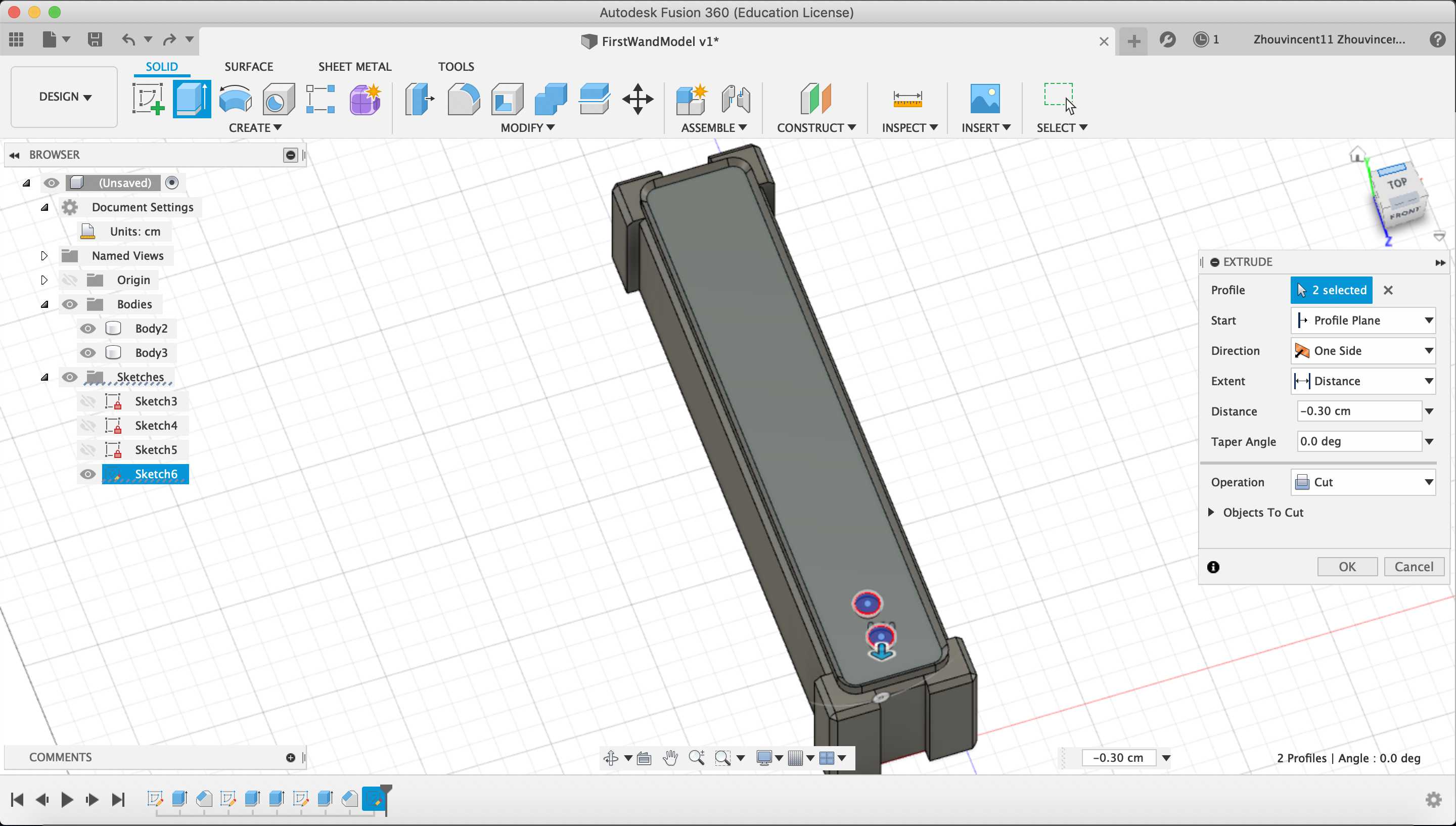
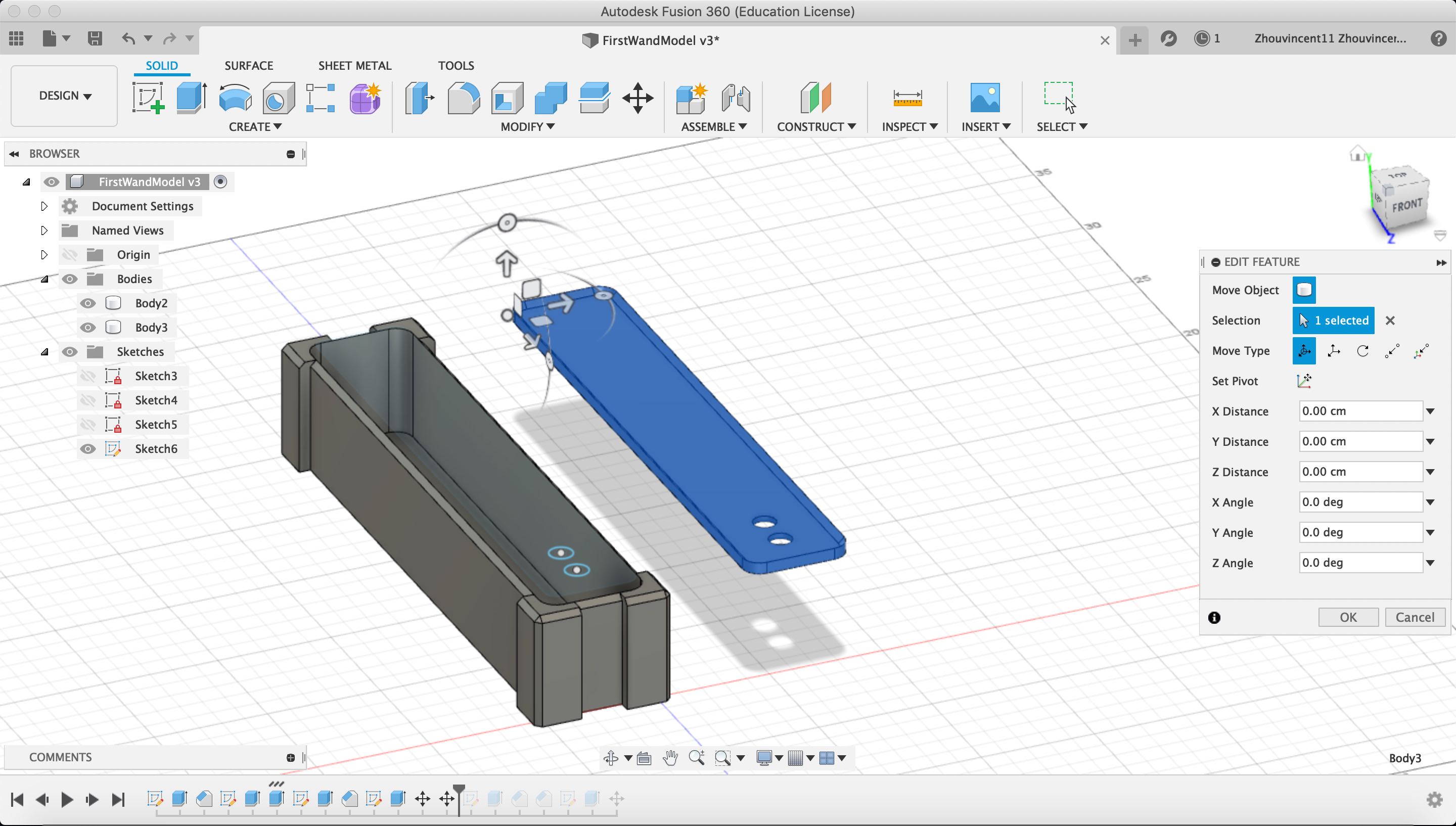
Here, I used the “Move” tool to move the lid next to the body for increased access to all sides of the lid.
Second, I created a sketch on the bottom of the lid and created 90º sectors out of the corner fillets of the lid.
I extruded the sketches downwards by 4.75 cm so that the lid would be flush with the top of the body in the hole.
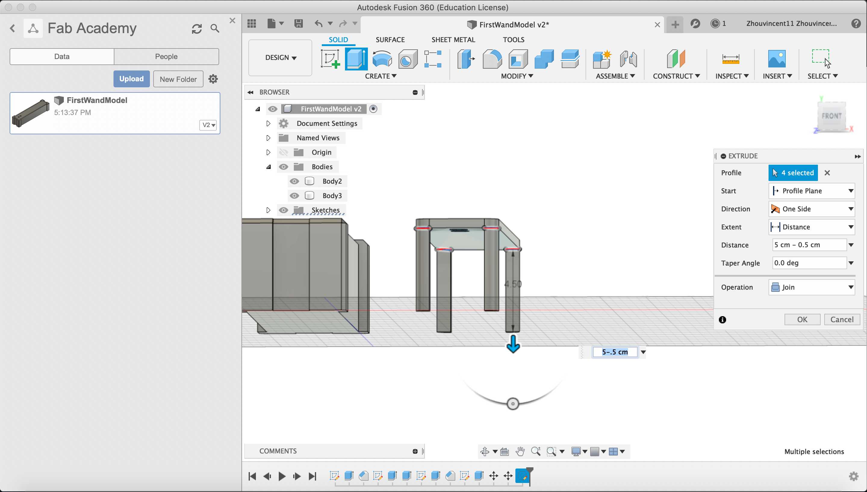
I chamfered the 90 degree angles on the legs with a distance of .50 cm to remove material and add more internal space in the body.
Third, I created another sketch on the top of the lid and created a rectangle .25 cm inside of the edge of the lid and .75 cm above the center of the topmost hole. I filleted the corners of the rectangle with a radius of .25 cm.
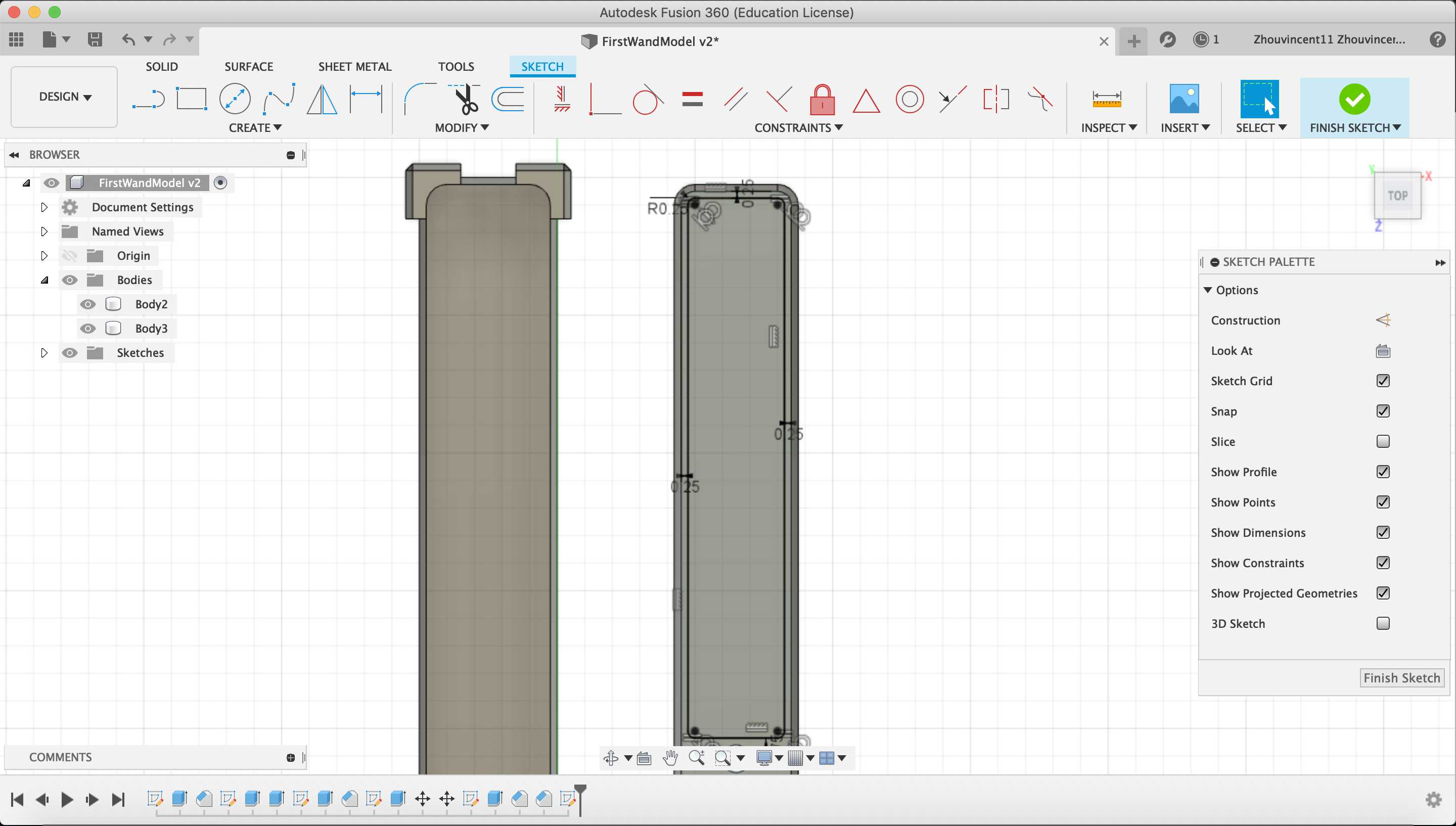
Then, I created a horizontal strip inside the rectangle with a width of .5 cm and then 1 cm below the top of the rectangle.
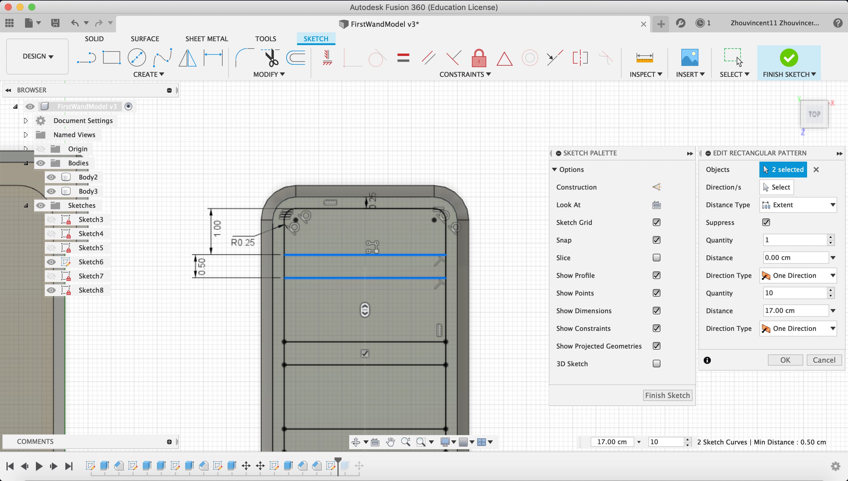
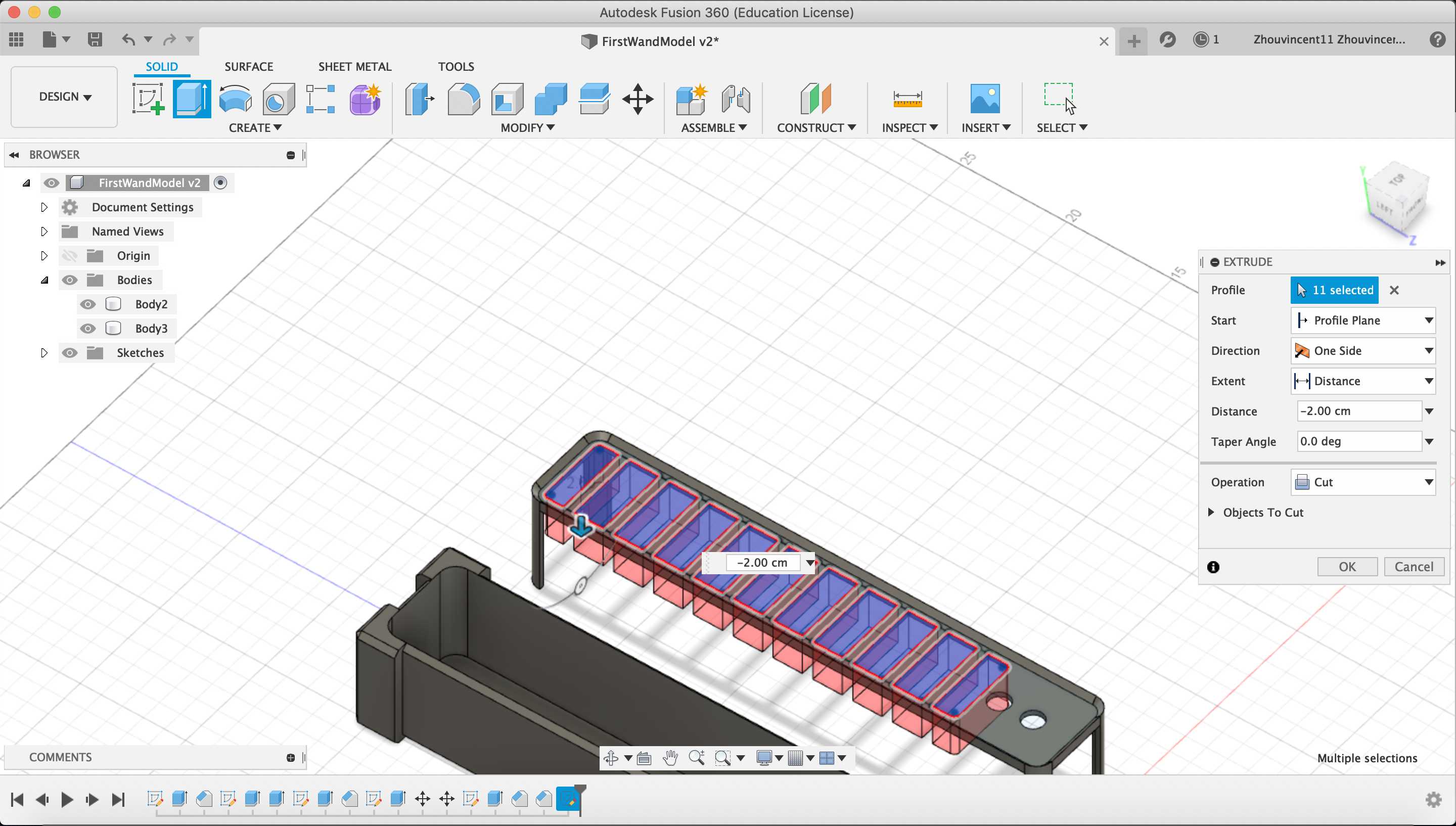
I selected the “Rectangular Pattern” tool and designated the horizontal strip. I set the strip to be duplicated 10 times over a distance of 17 cm downwards.
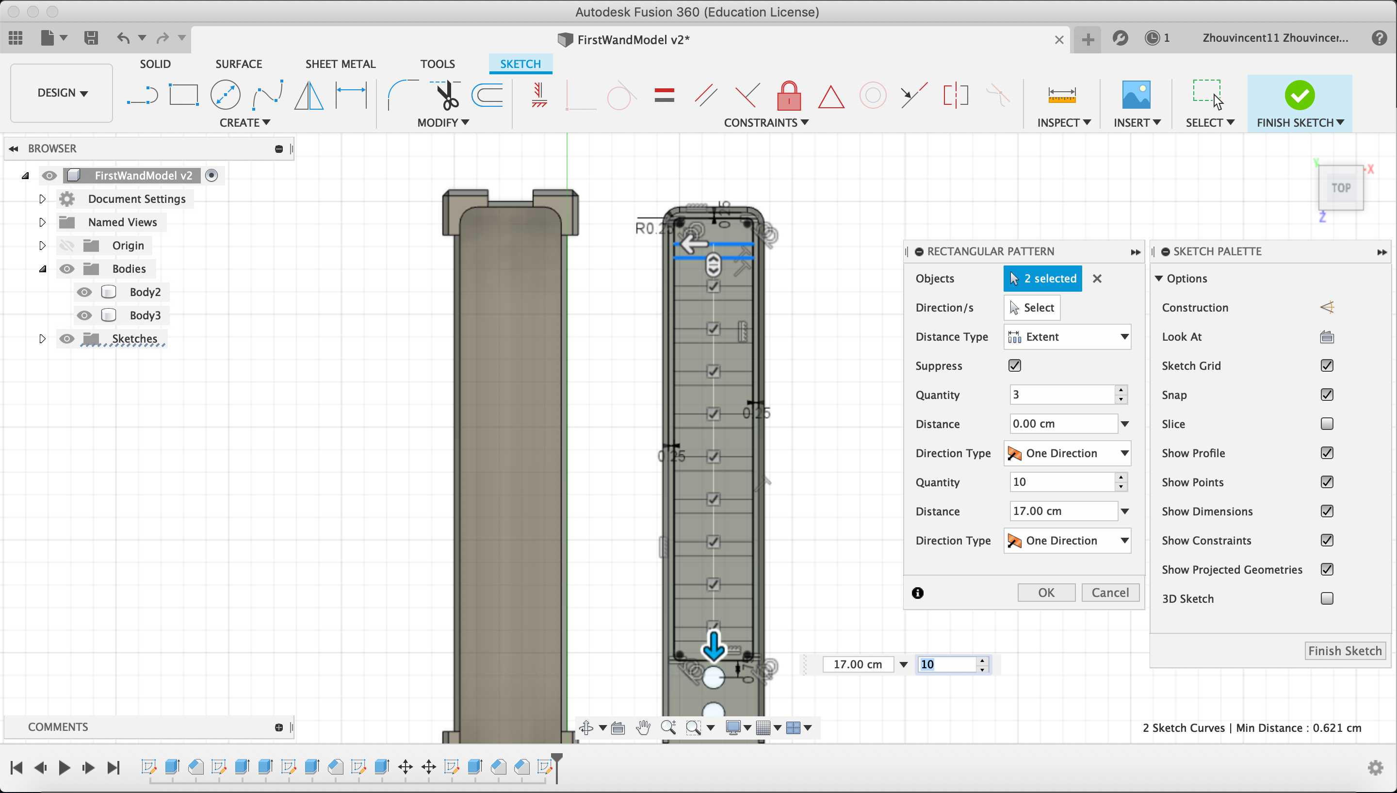
I cut extruded the sketch through the lid. The perforations in the lid will serve as an aesthetic grill for the wand.
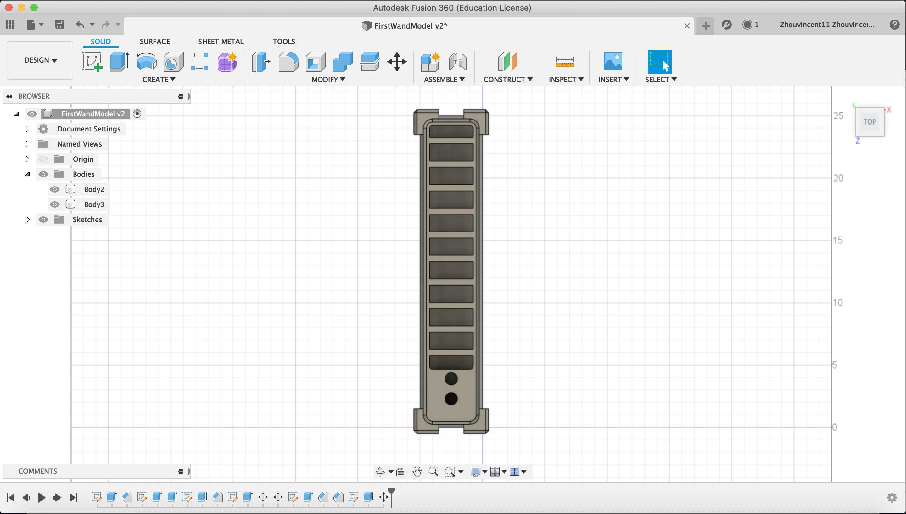
Finally, I moved the lid back into the the body and the CAD design of my wand in Fusion 360 was finished.
Design Drawing
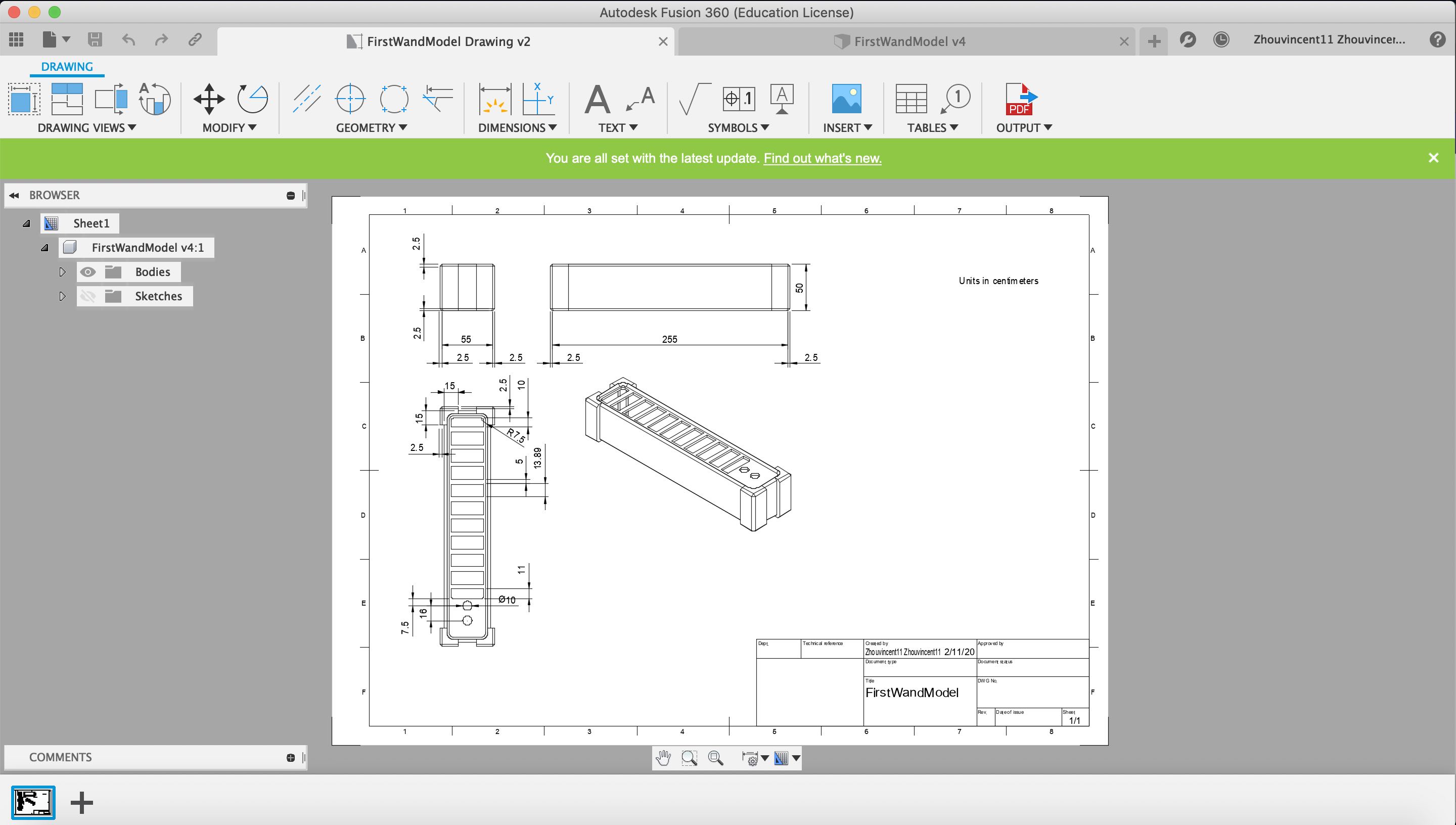
After finishing the wand model, I decided to create a drawing detailing all dimensions of the model. In order to do, I clicked on the dropdown in the upper left hand corner, hovered over the “Drawing” tab, and selected the “From Design” option.
Fusion 360 created a new drawing file, and using the “Base View” tool, I dragged out a base view of my design onto the drawing. Then, I dragged out different orthogonal views of my design using the “Projected View” tool by dragging the tool to the right, lower right, and bottom of the base view. I also annotated the design using the “Dimension” tool much like the way I used the dimension tool in the design.
SolidWorks
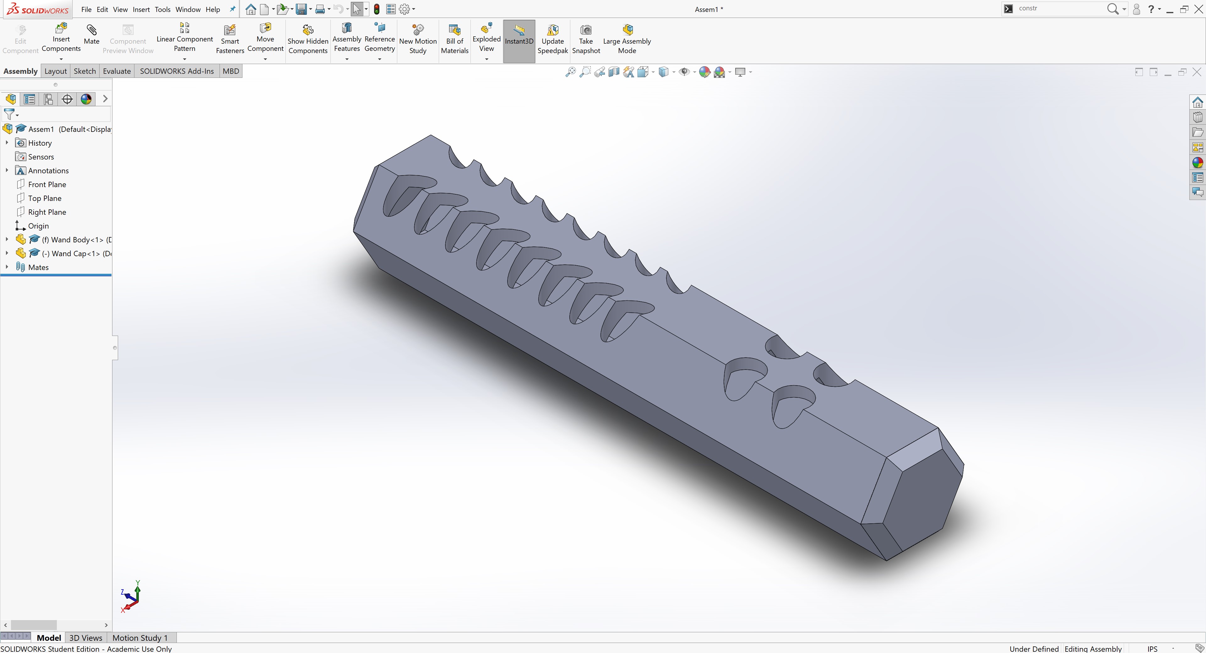
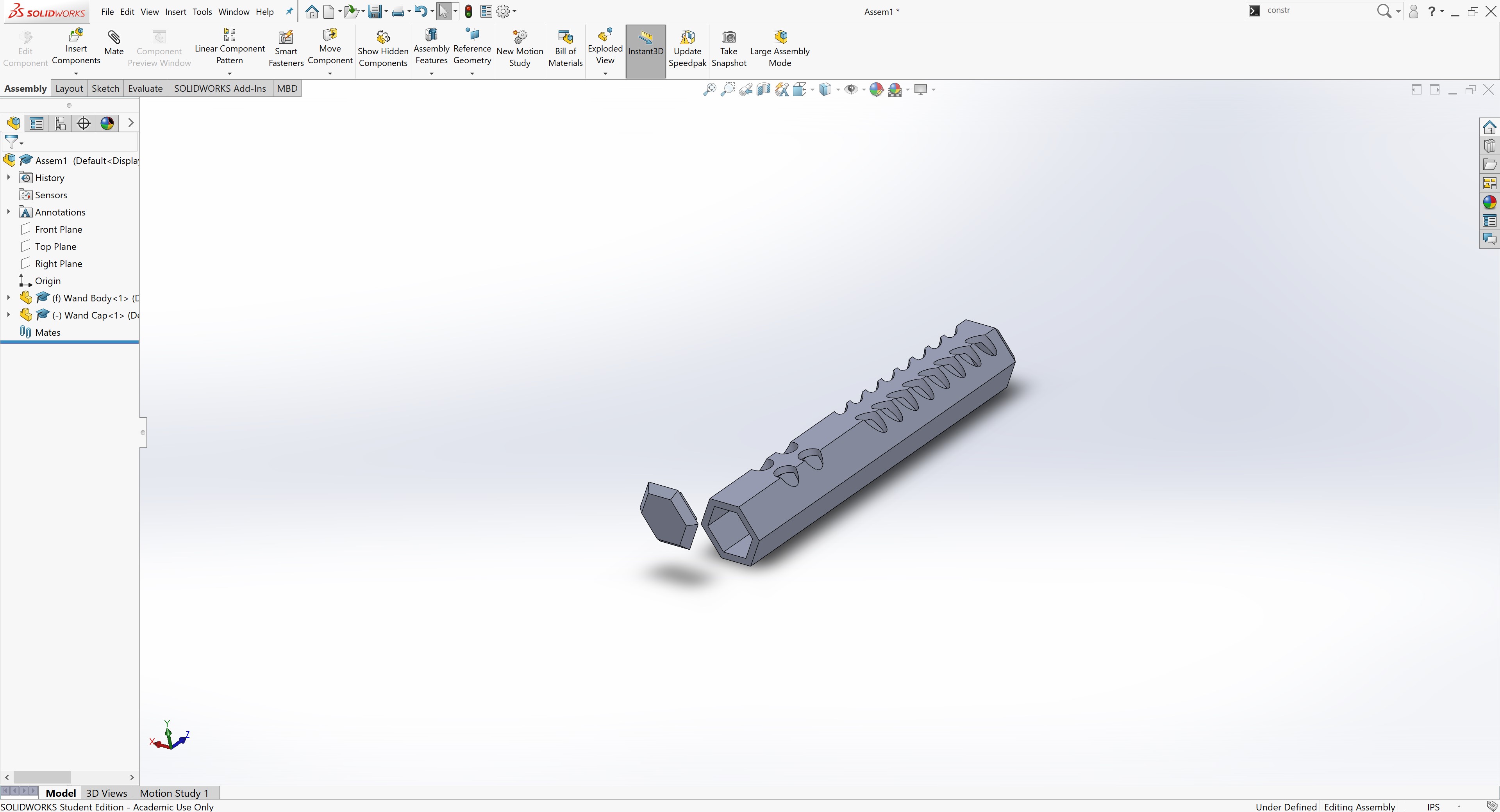
I also had a bit of experience using SolidWorks, so I decided to reimagine the wand design in SolidWorks. This time I wanted a more hexagonal design for the wand and I wanted two components.
Unlike Fusion 360, SolidWorks treats individual parts as seperate files and the assembly as a sperate file. Therefore, in order to have two components, I would need to create two parts and one assembly. However, Fusion 360 and SolidWorks share many aspects and functionalities.
Body Design
First, I choose to create a part to model the wand body.
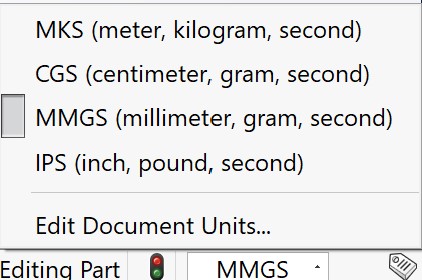
I had to switch the units to MMGS (Millimeter, Gram, Second)
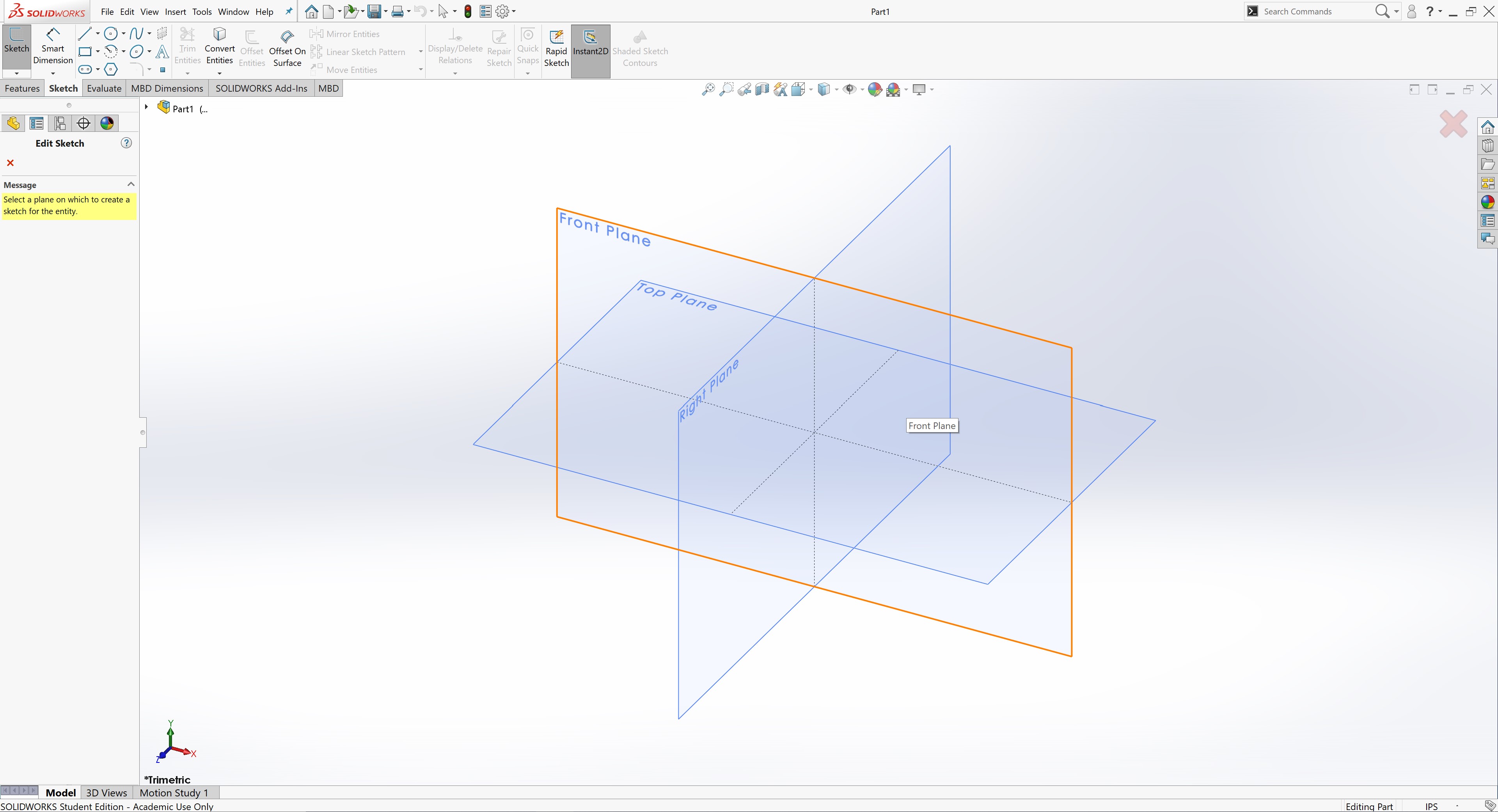
I created a sketch on the front plane.
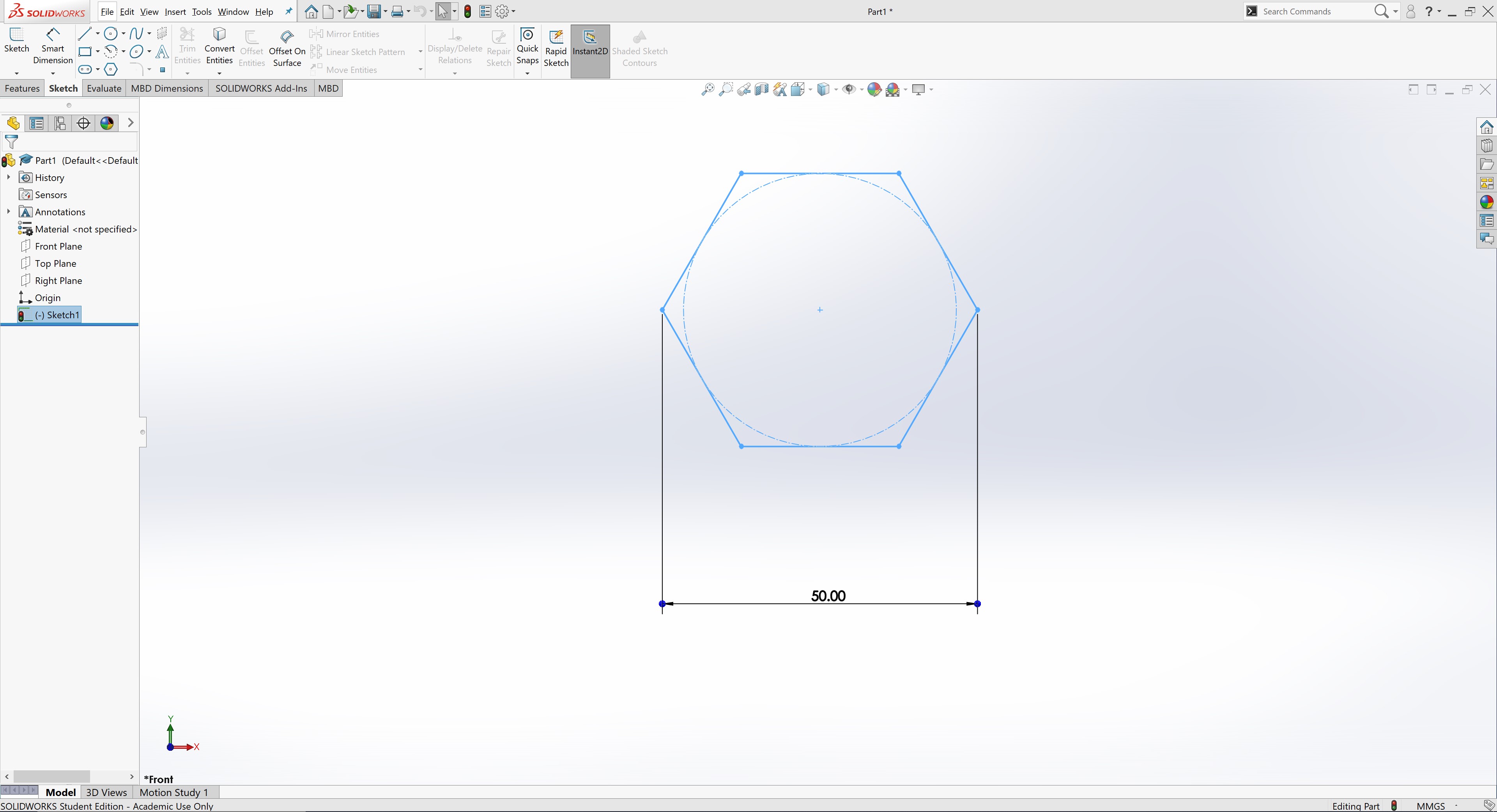
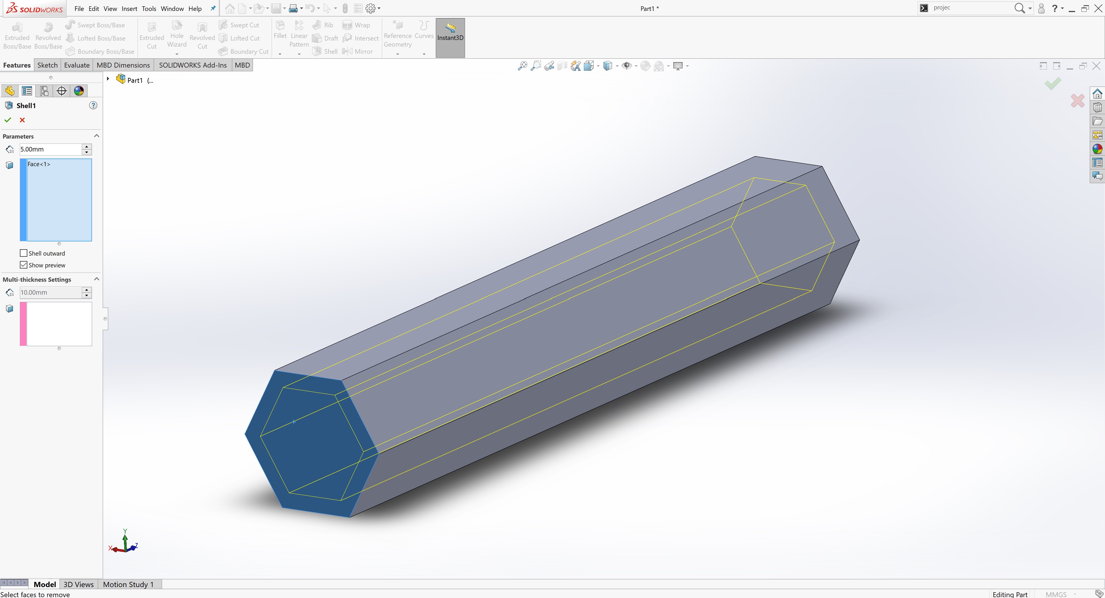
I selected the “Polygon Tool” and created a normal hexagon dimensioned to be 20 mm across.
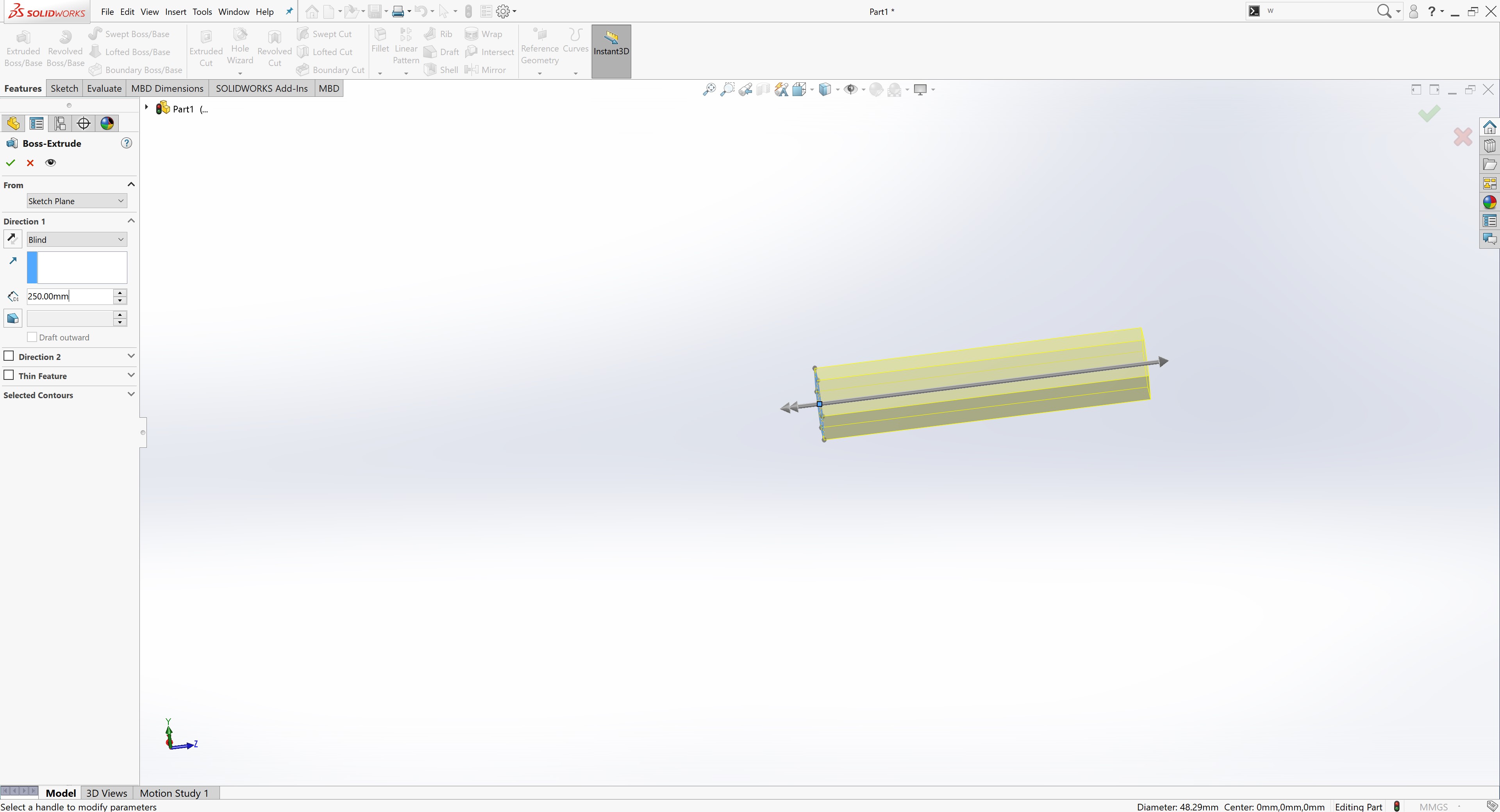
Next, I extruded the sketch 250 mm out.
To create internal space, I used the “Shell” tool by selecting the face to open up and inputing the thicknessx of the shell to be 5 mm.
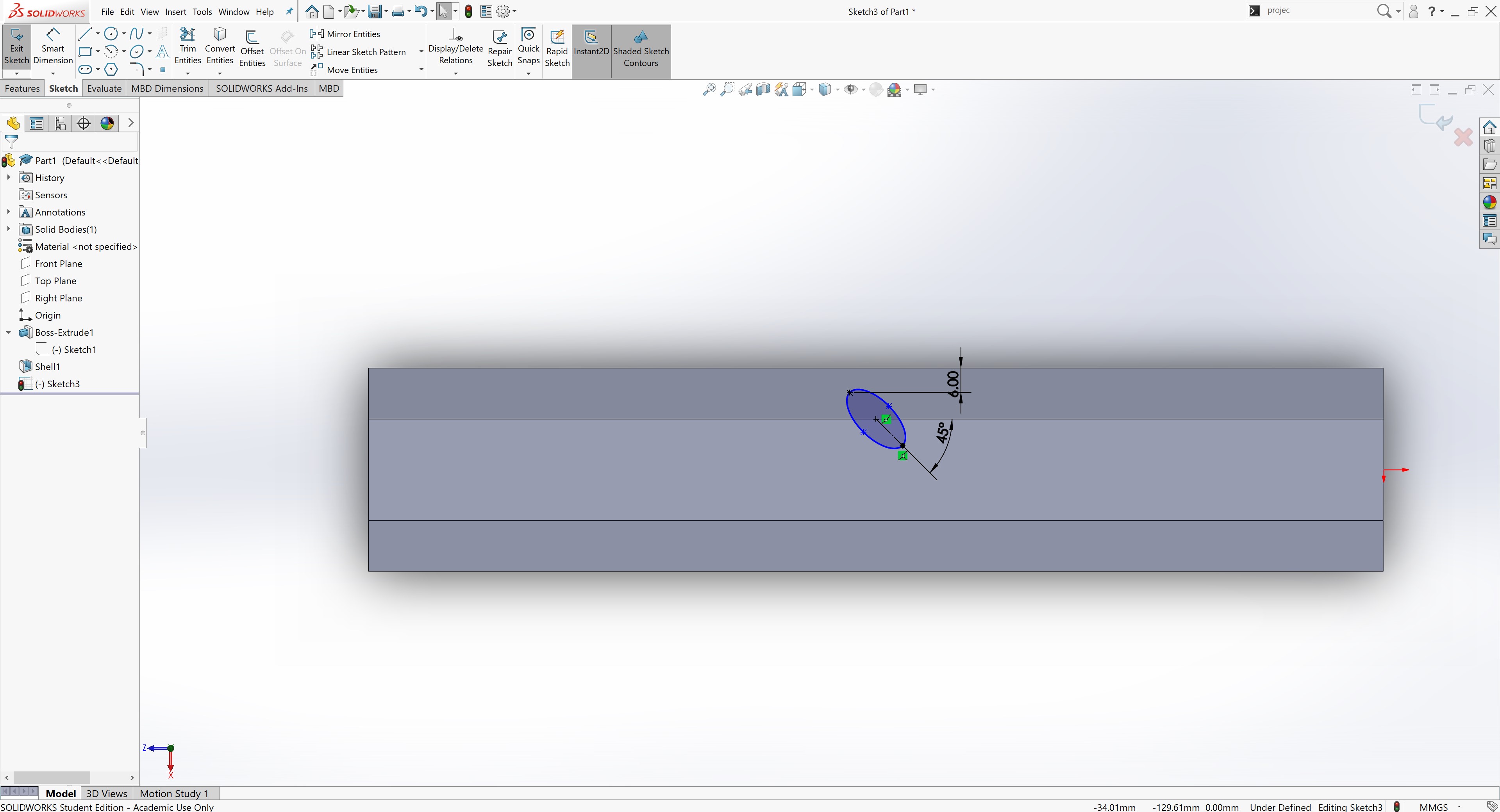
Then, I created a sketch on top of the body for any shape that I need to cutout from the top of the body, such as aesthetic perforations and button holes.
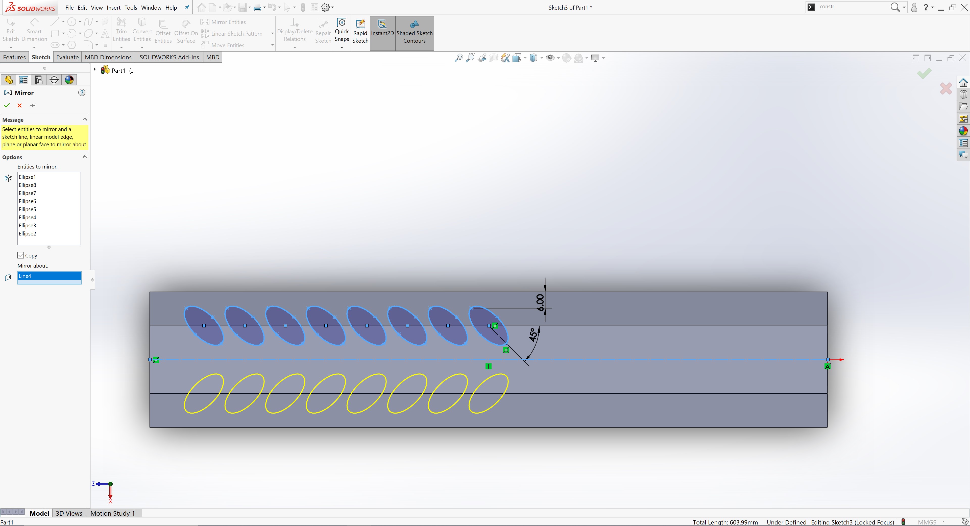
I created an ellipse tilted at a 45º angle from the edge of body. This was accomplished using a constuction line running from the center to the bottom of the ellipse and a dimension between the line and the edge. I made sure to space the top of the ellipse 6 mm away from the outer edge so that the cut extrude would not compromise the sides.
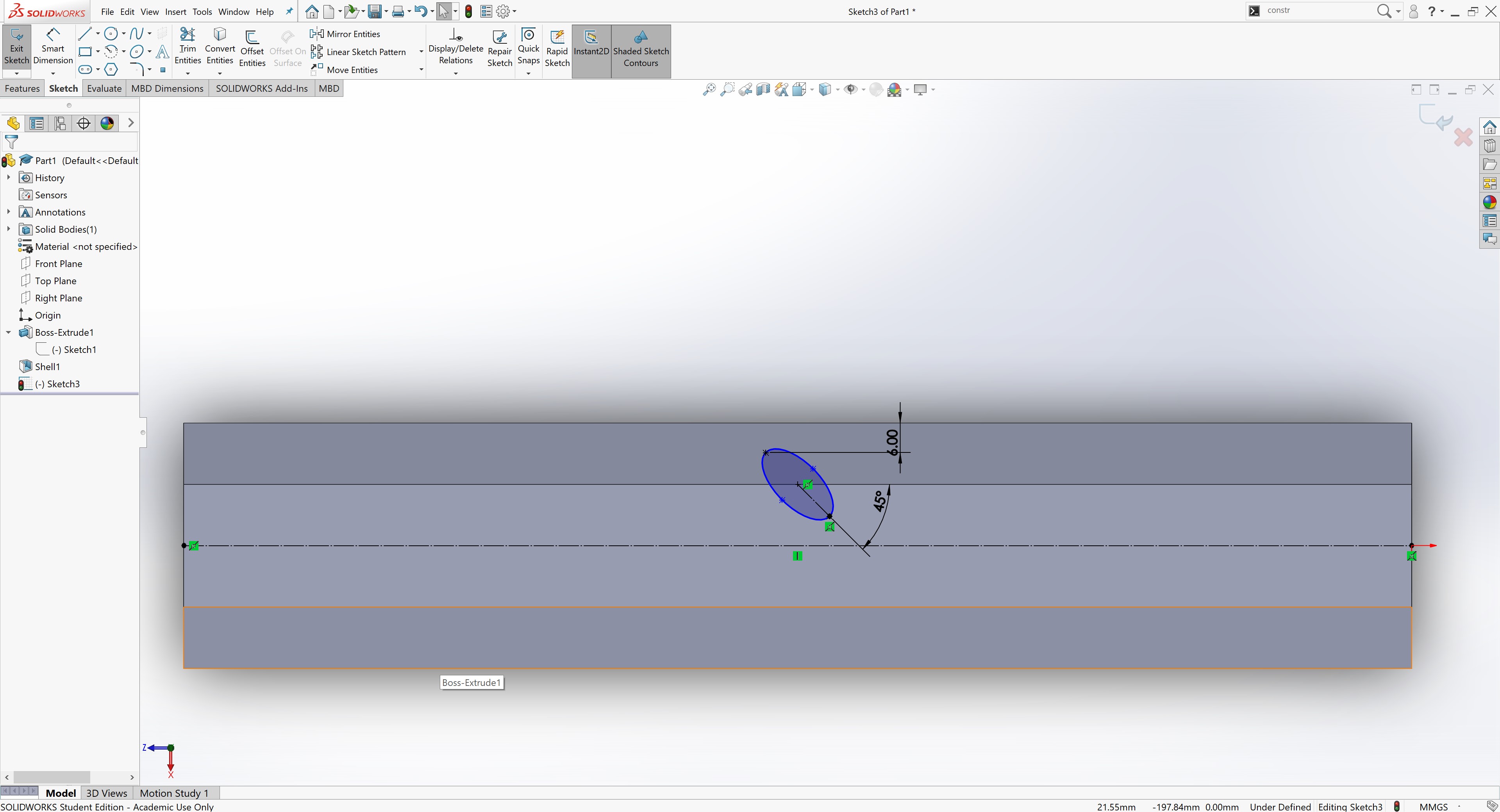
In order to utilize a mirror, I created a centered construction line running from one end of the wand body to the other.
I duplicated the ellipse 8 times toward the left end of the body using a linear pattern.
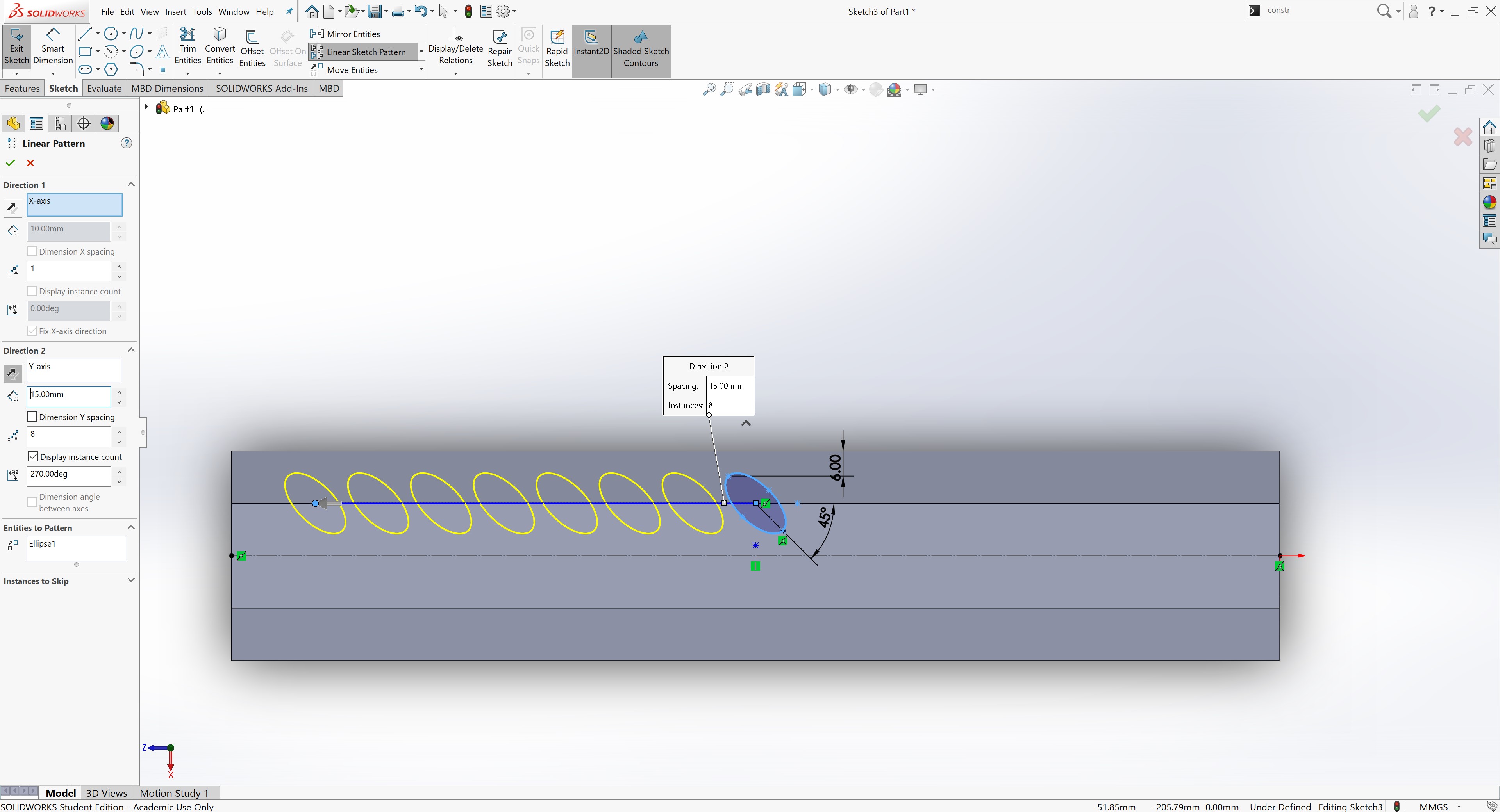
Next, I mirrored the linear pattern over the center line running down the body.
For the buttons, I created two buttons with equal diameters of 15 mm and equal spacing from the center line of 10 mm.
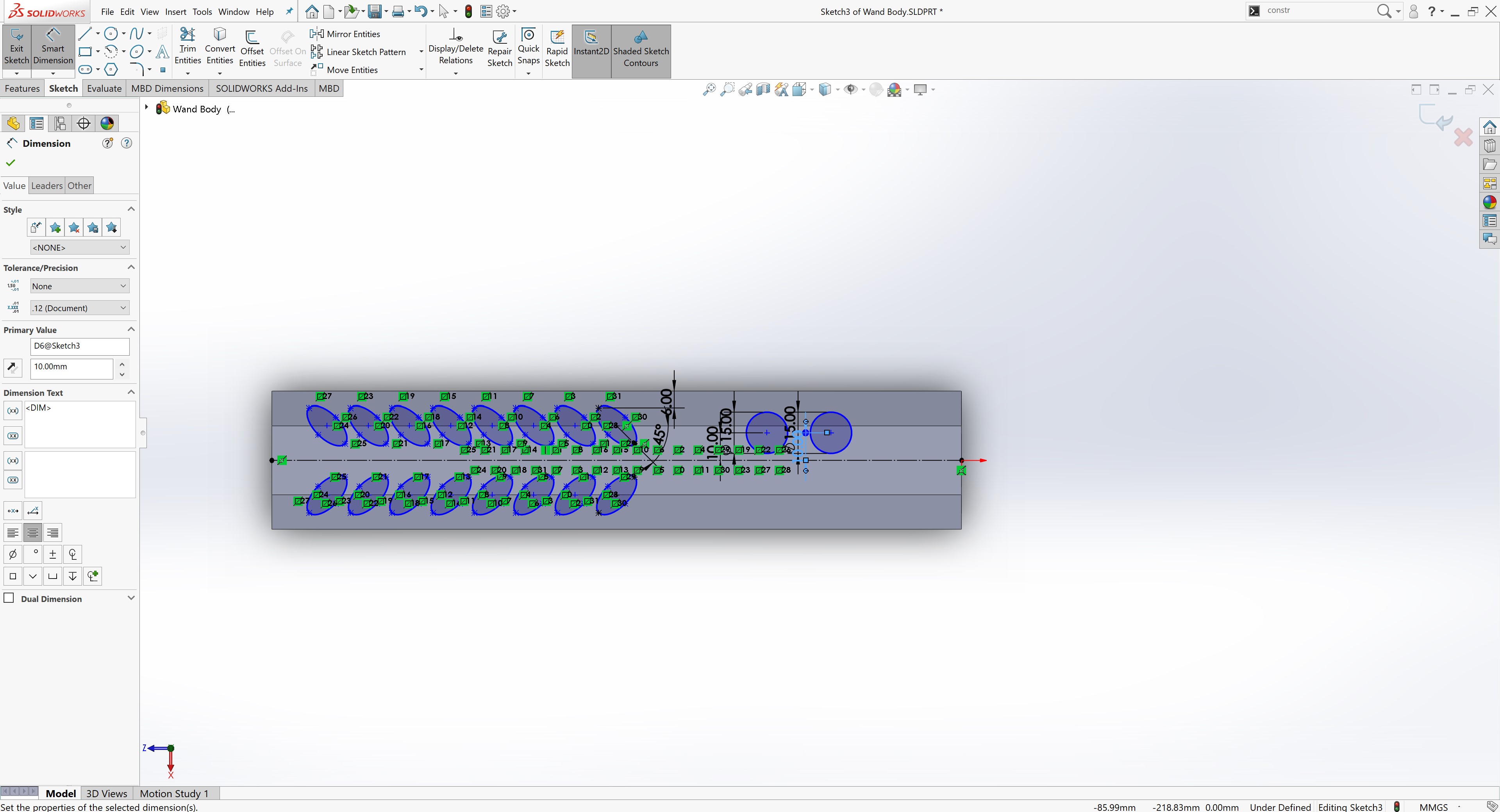
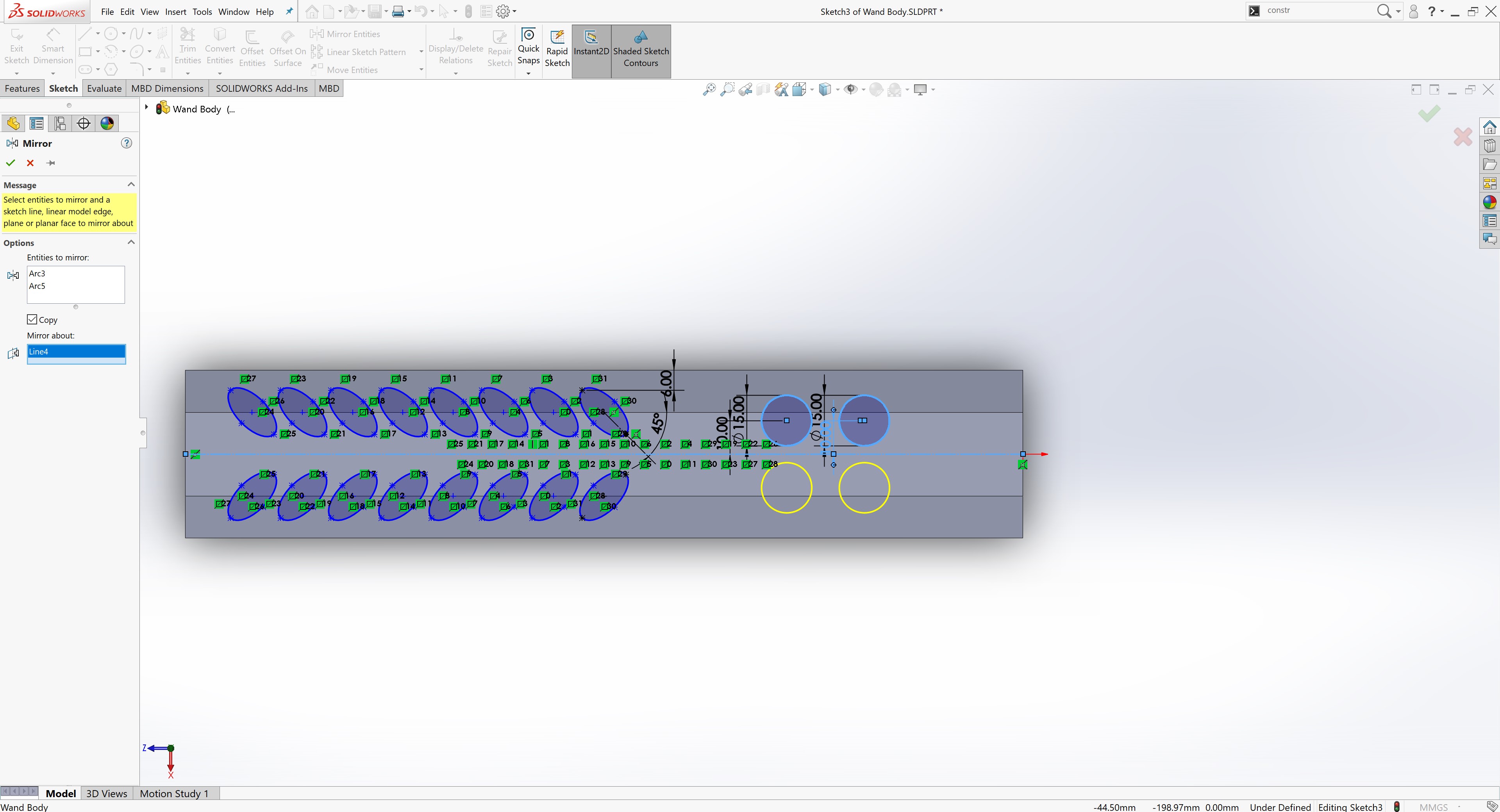
I mirrored the buttons over the center line.
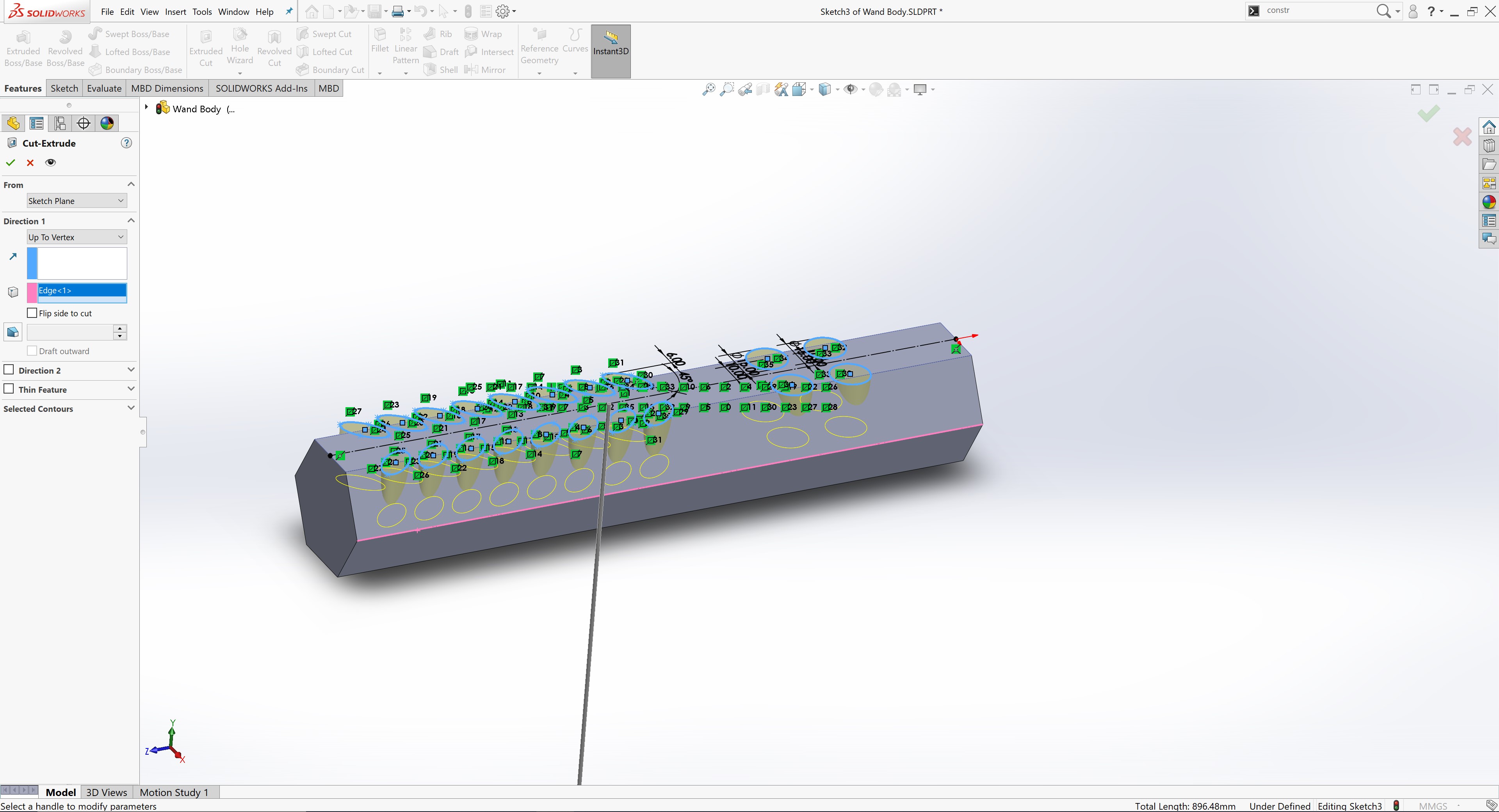
Then, I cut extruded the top sketch down until the middle edge by selecting the vertex.
Finally, I chamfered the closed end of the body with a distance of 5 mm.
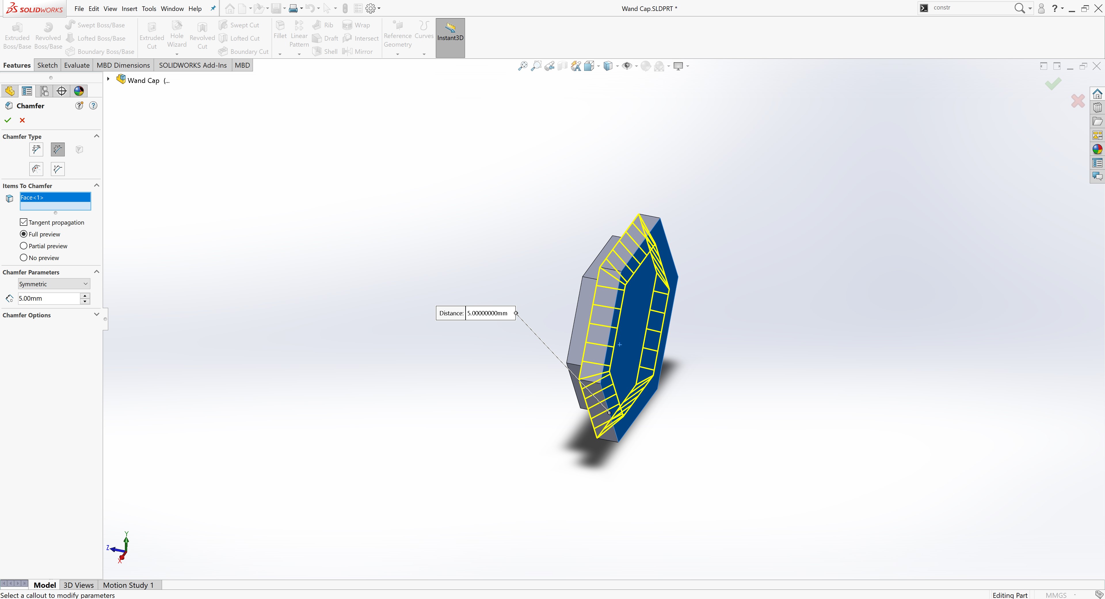
Cap Design
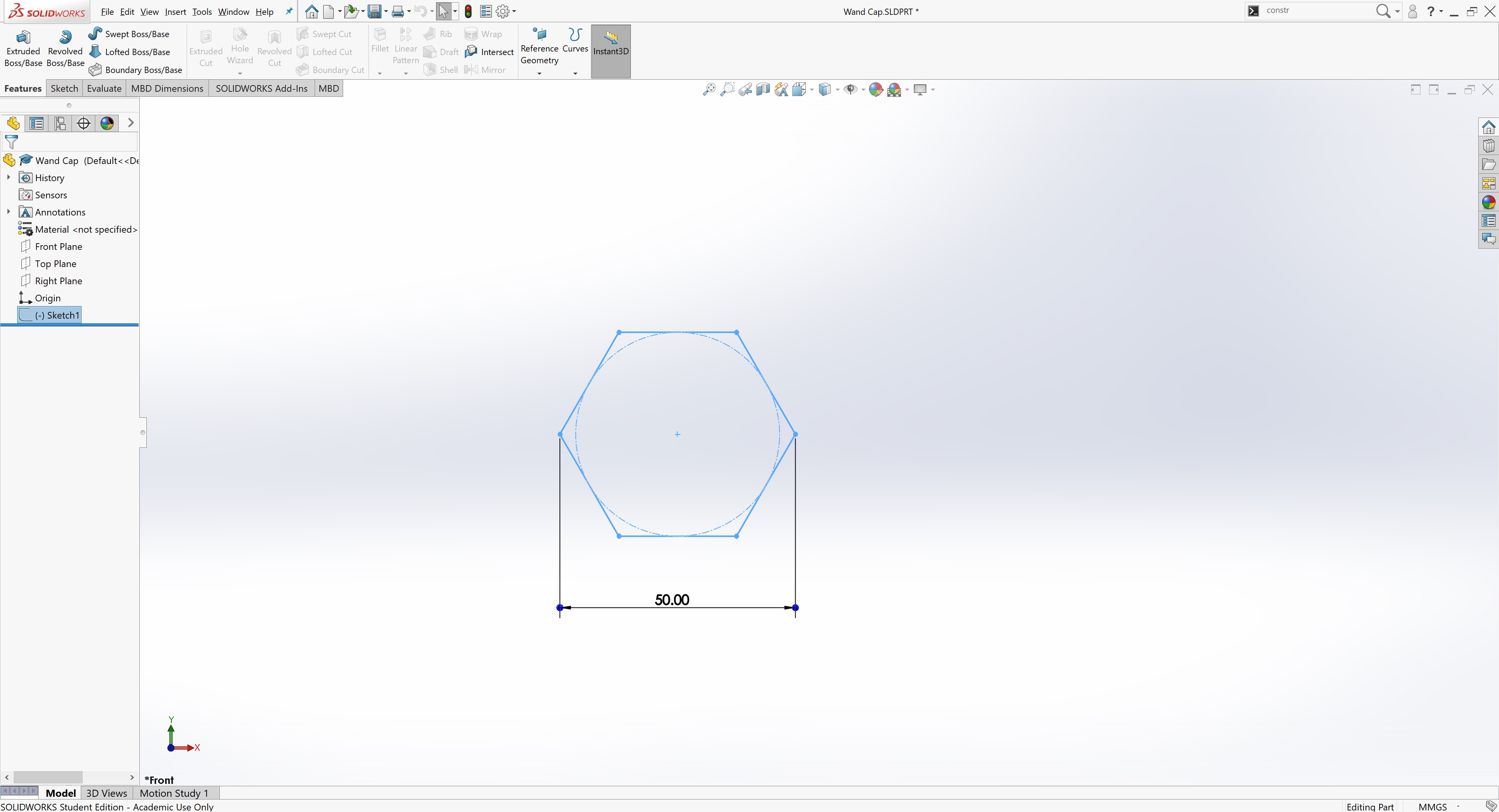
To model the cap for the wand, I choose to create another part. I created a sketch on the front plane and replicated the same profile of main body.
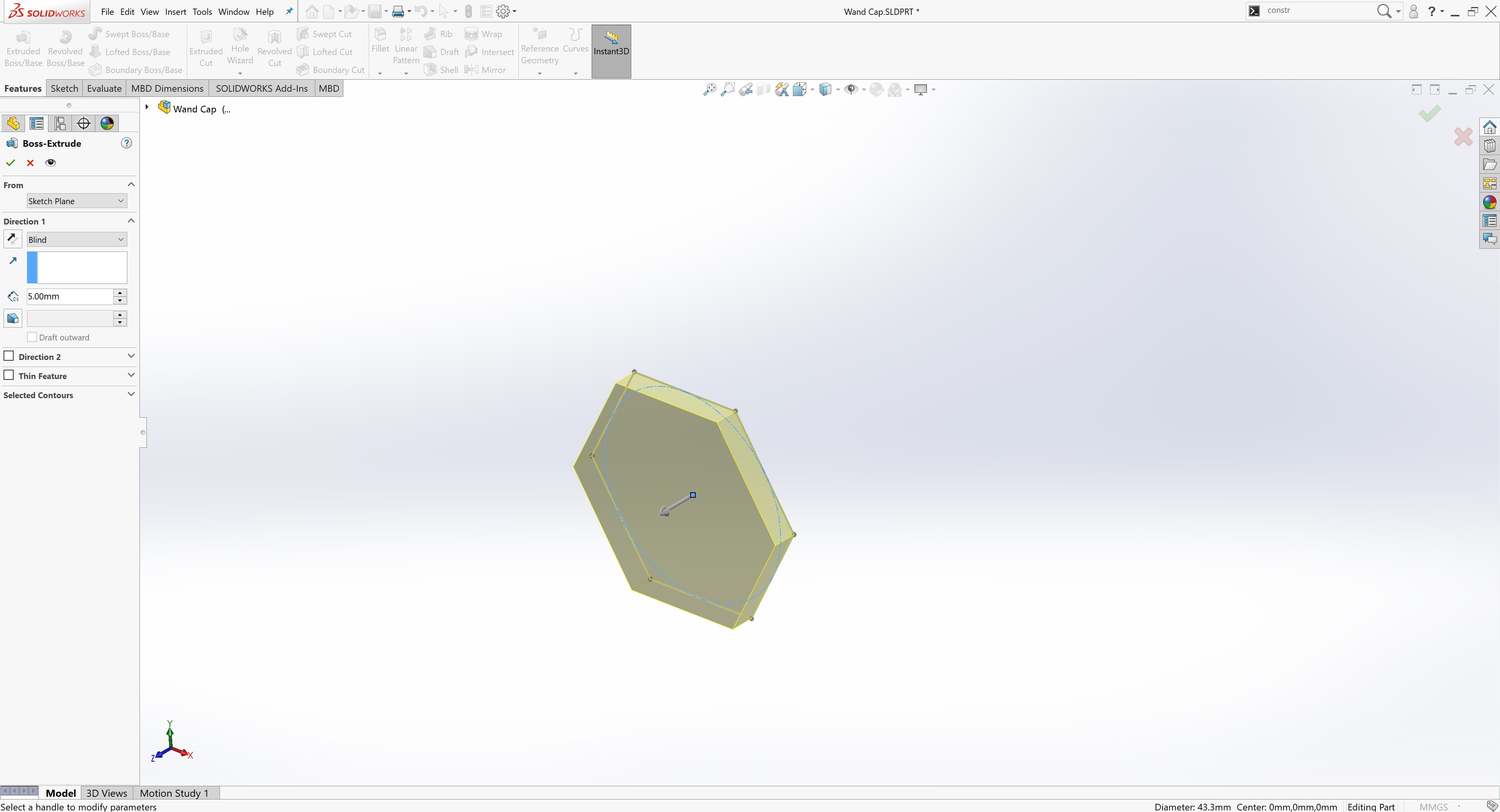
Next, I extruded the sketch by 5 mm.
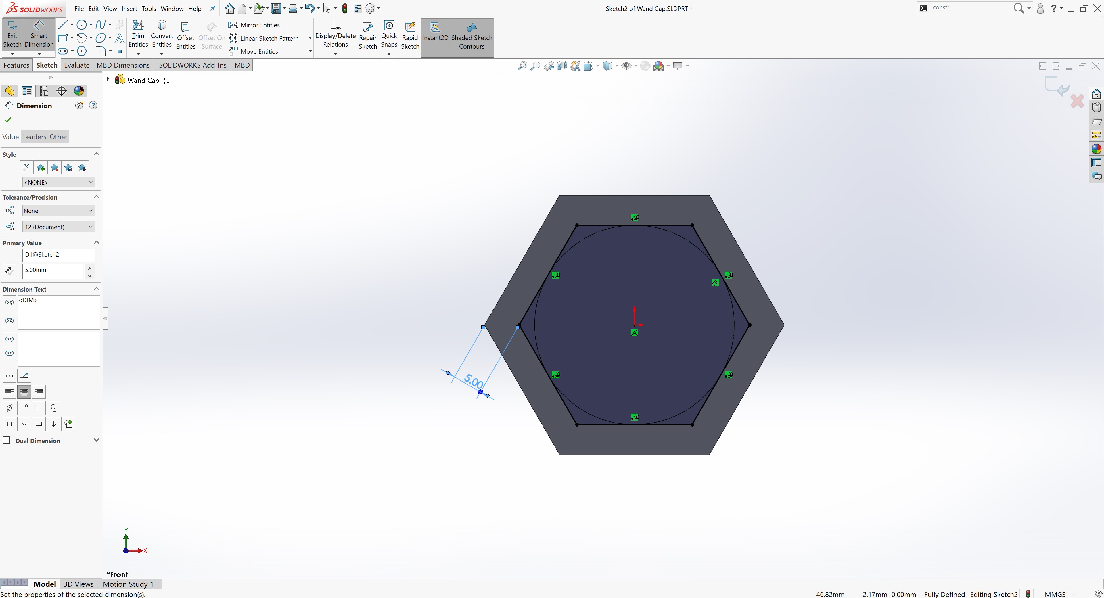
I created another sketch on the back of the cap with a regular hexagon the shape of the interior of the wand body. This meant creating a regular hexagon dimensioned to be 5 mm inside the outer hexagon.
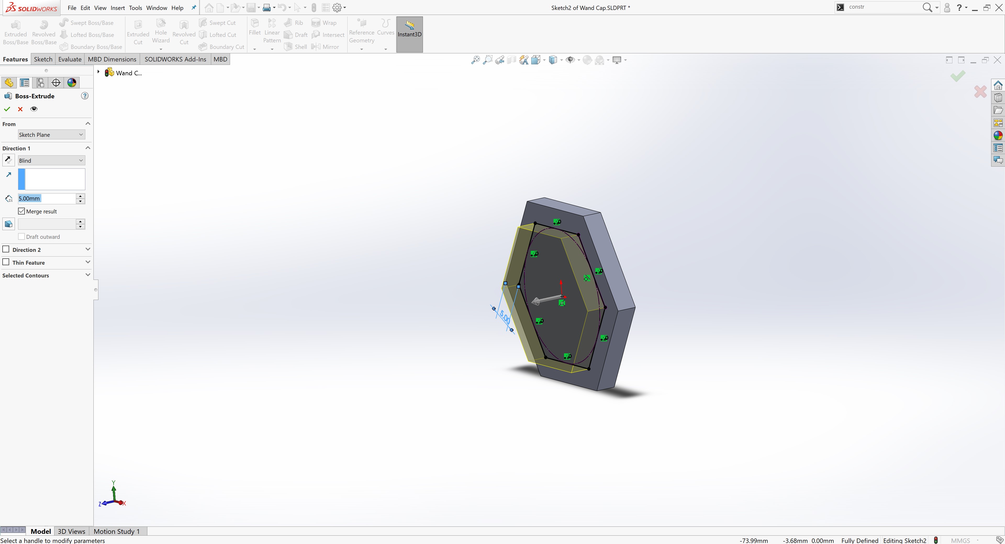
I extruded the sketch by 5mm.
Finally, I chamfered the cap with a distance of 5mm to match the closed end of the body.
Assembly
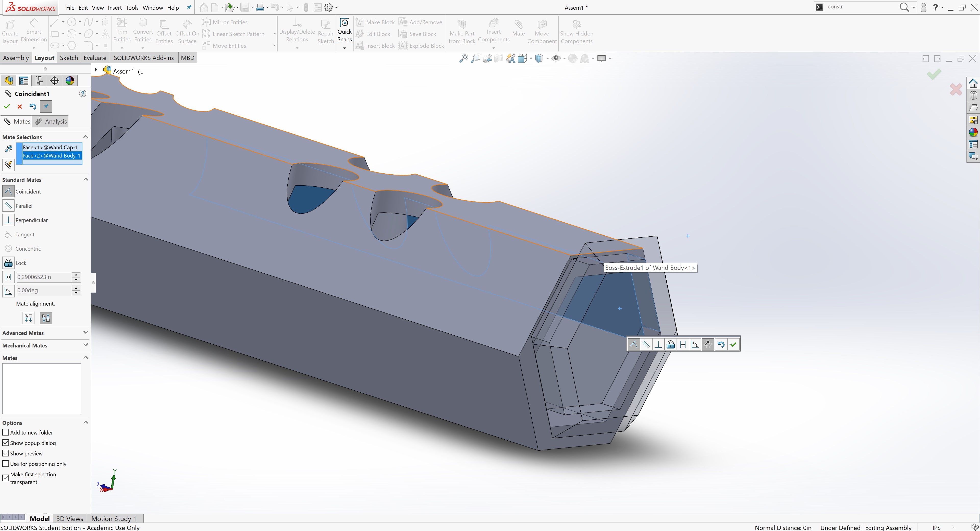
To join the cap and body together, I choose to create an assembly. When prompted to add parts, I selected the wand cap and body.
I used the “Mate” tool and designated a coincident relationship between the inner hexagon faces of the cap and the inner hexagon faces of the body. A coincident relationship means that the faces touch.
Finally, I finished the CAD design for my wand in SolidWorks.