6. 3D Scanning and printing
Group Project:
- use the test equipment in your lab to observe the operation of a microcontroller circuit board
Individual Project:
- Design and 3D print an object (small, few cm3, limited by printer time) that could not be made subtractively
- 3D scan an object (and optionally print it)
3D Printing
Modeling
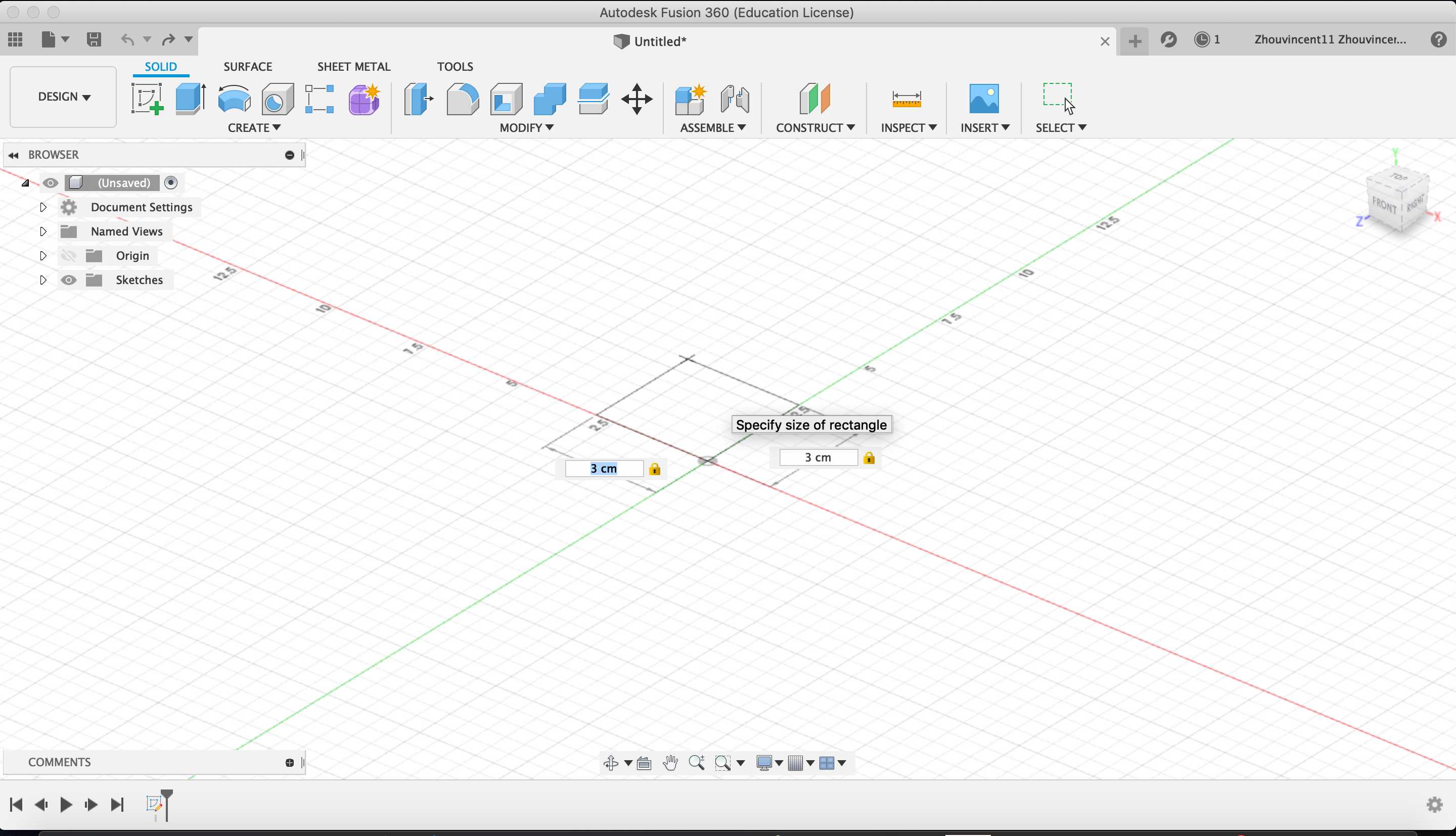
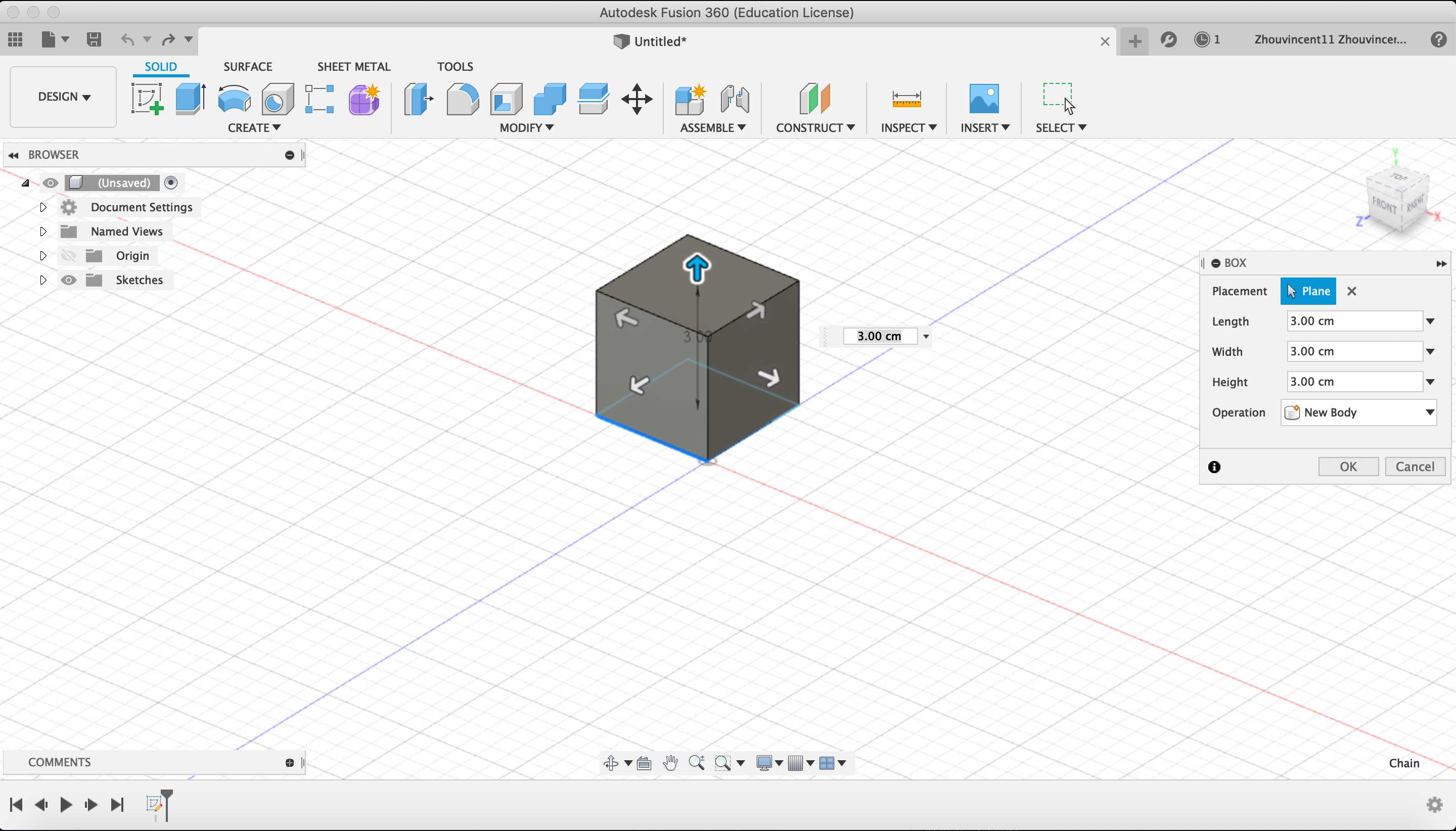
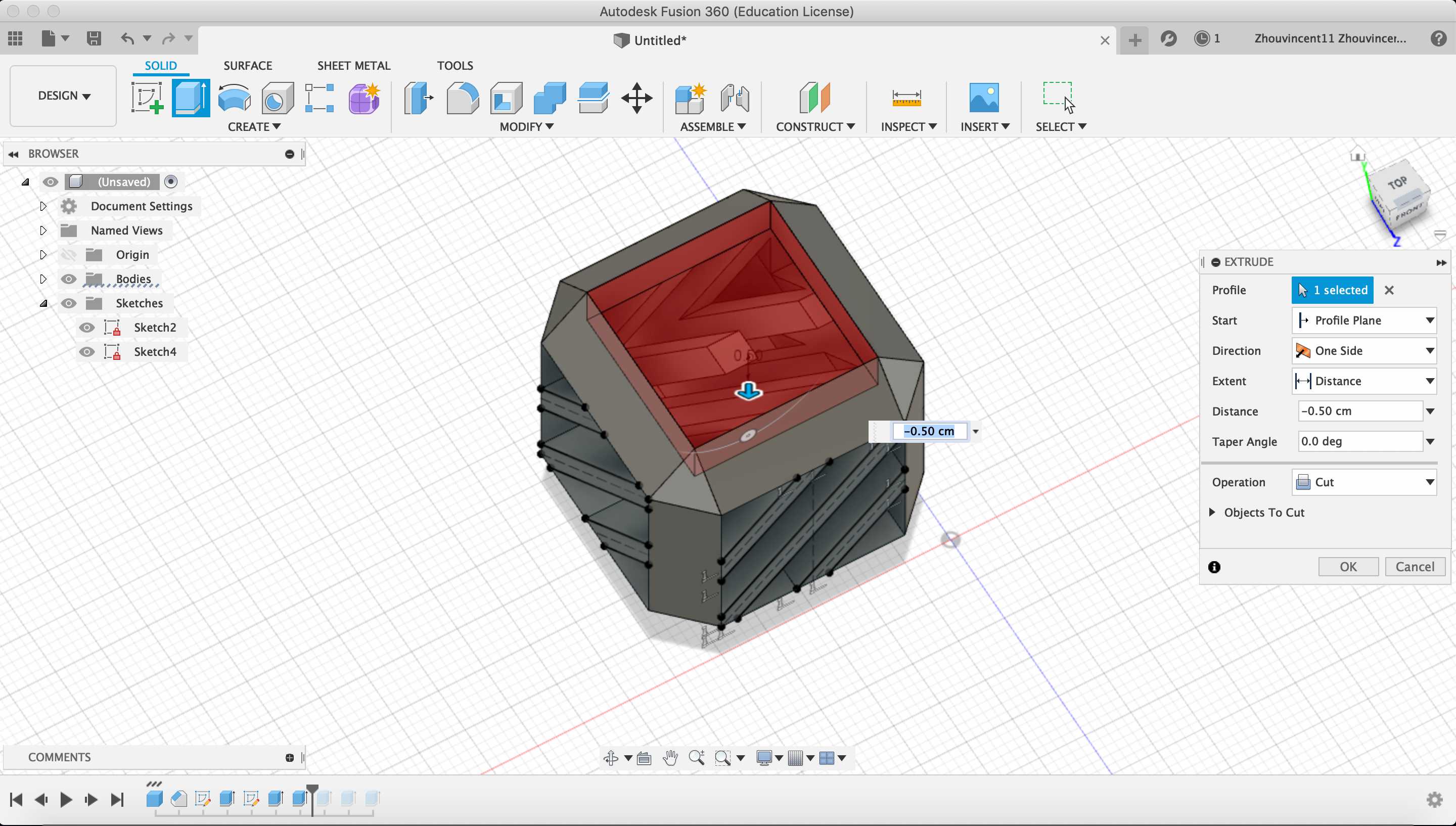
First, I created a box that was constrained to 3 x 3 x 3 cm to decrease printing time.
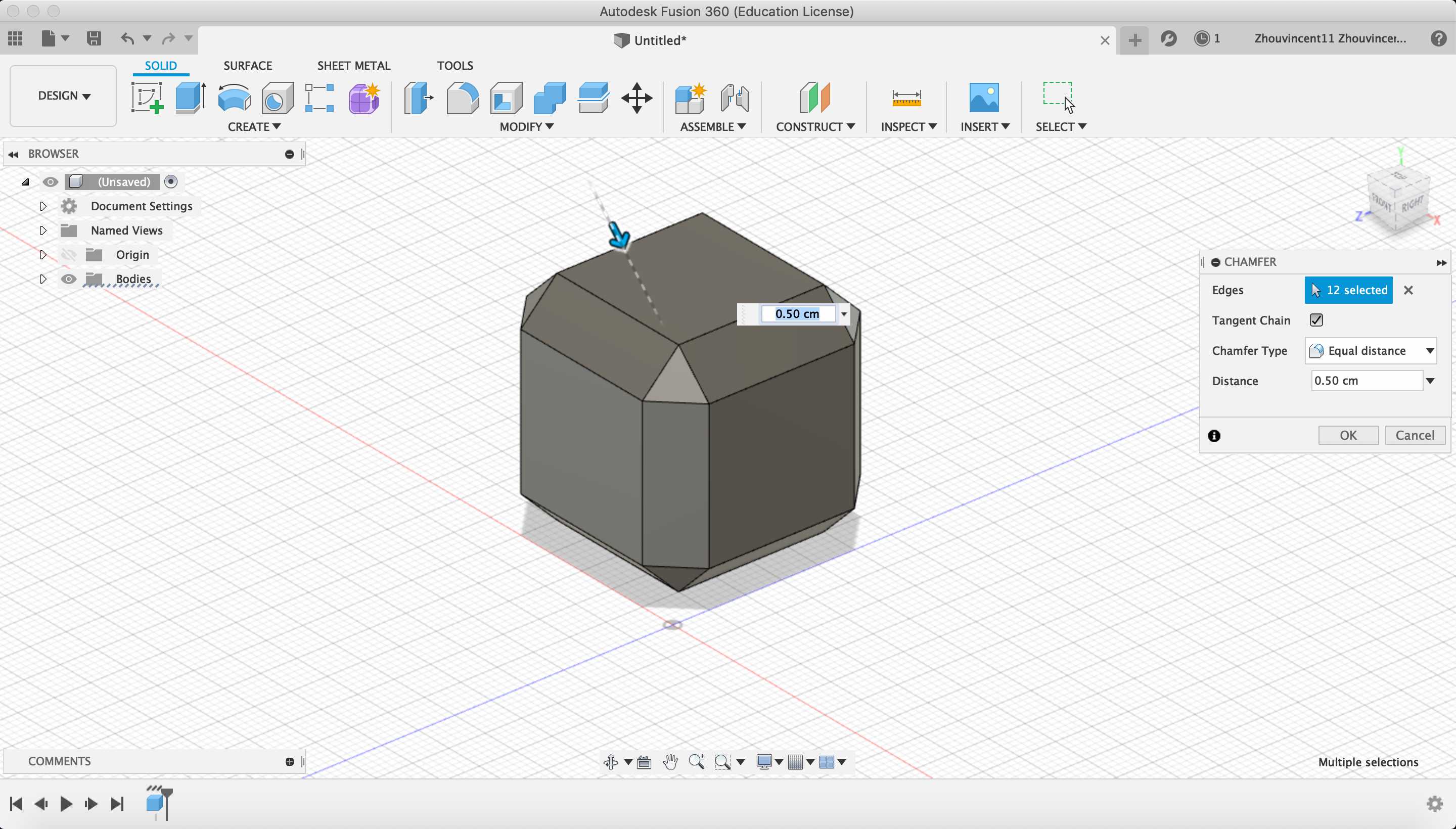
Next, I chamfered the edges of the box in order to utilize the ability of the printer to print 45º inclines.
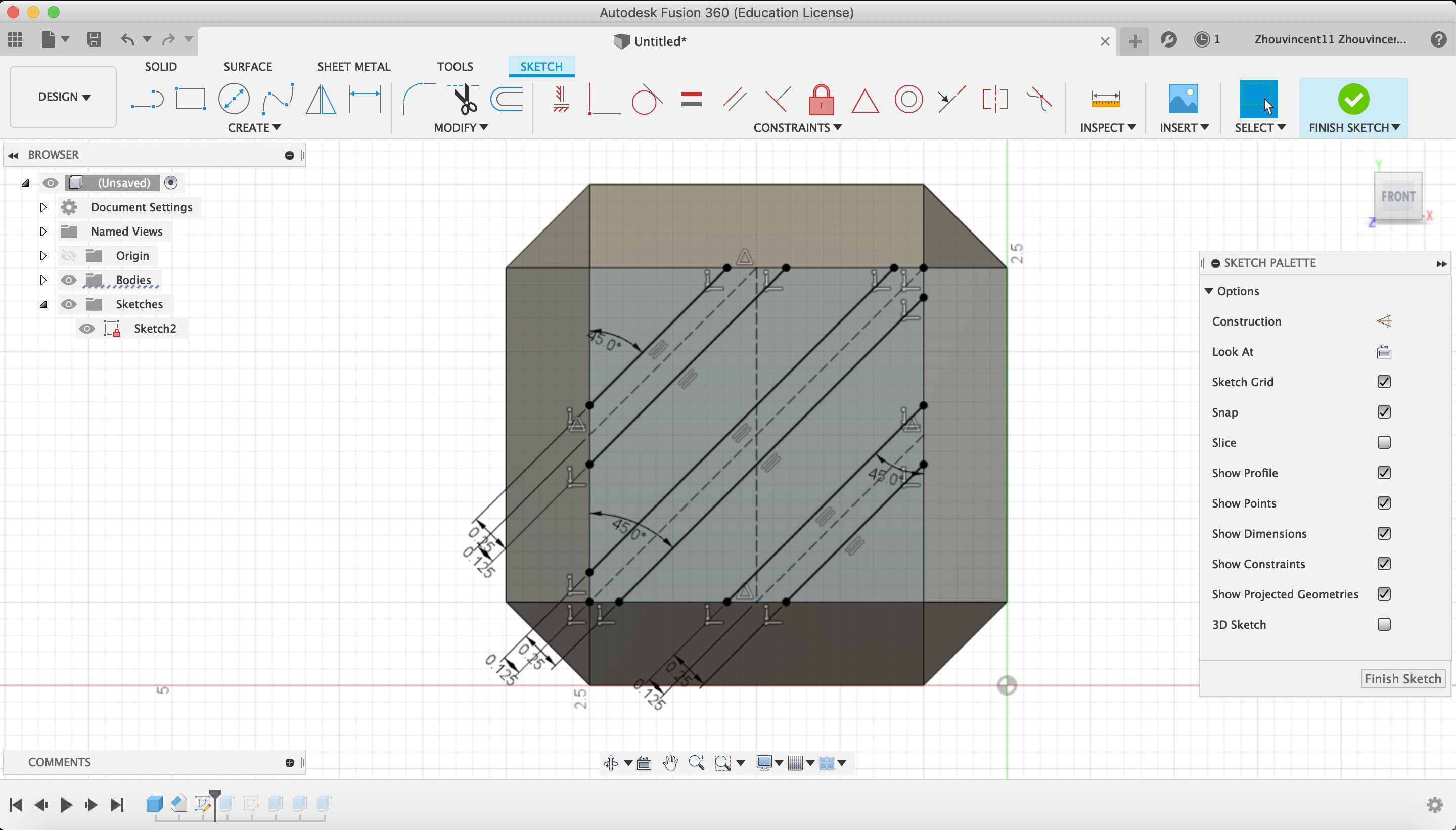
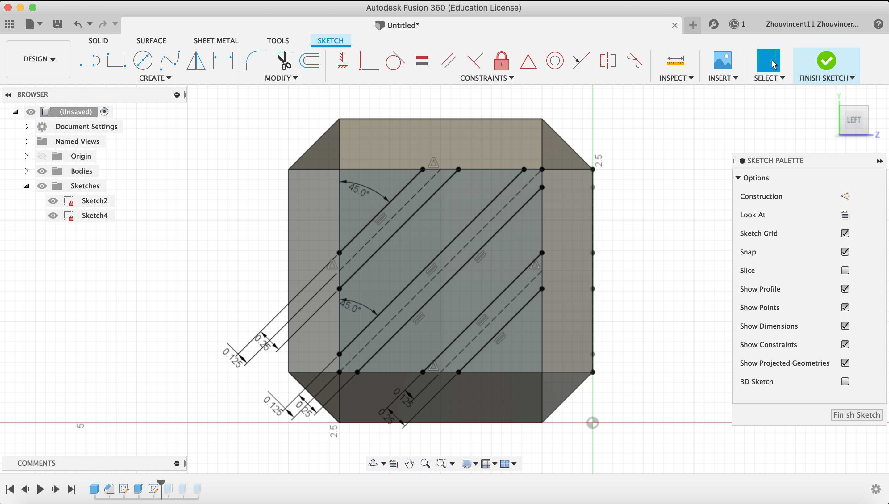
Then, I decided to add some features to the box that could not be made subtractively. I decided to add a sketch on the side of the box and segment the side into diagonal regions.
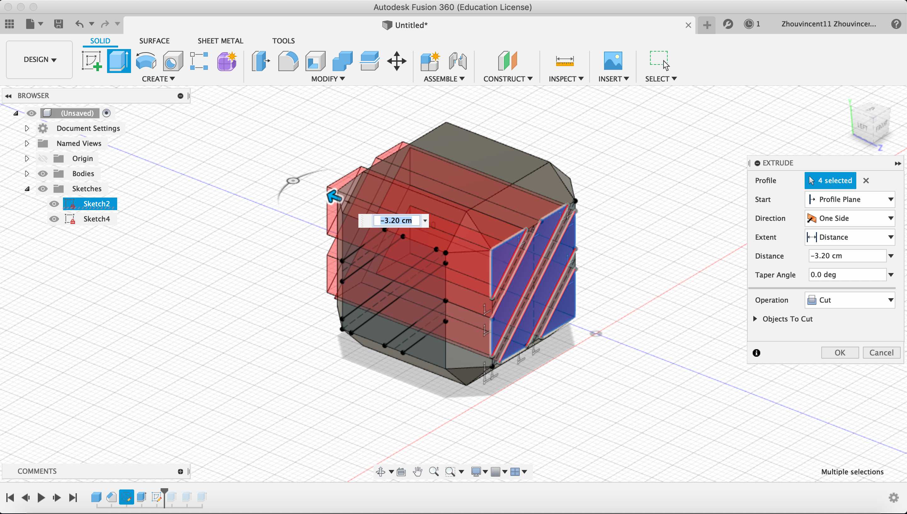
By extruding through the side, the box now has features that would be difficult to reproduce in substractive manufacturing.
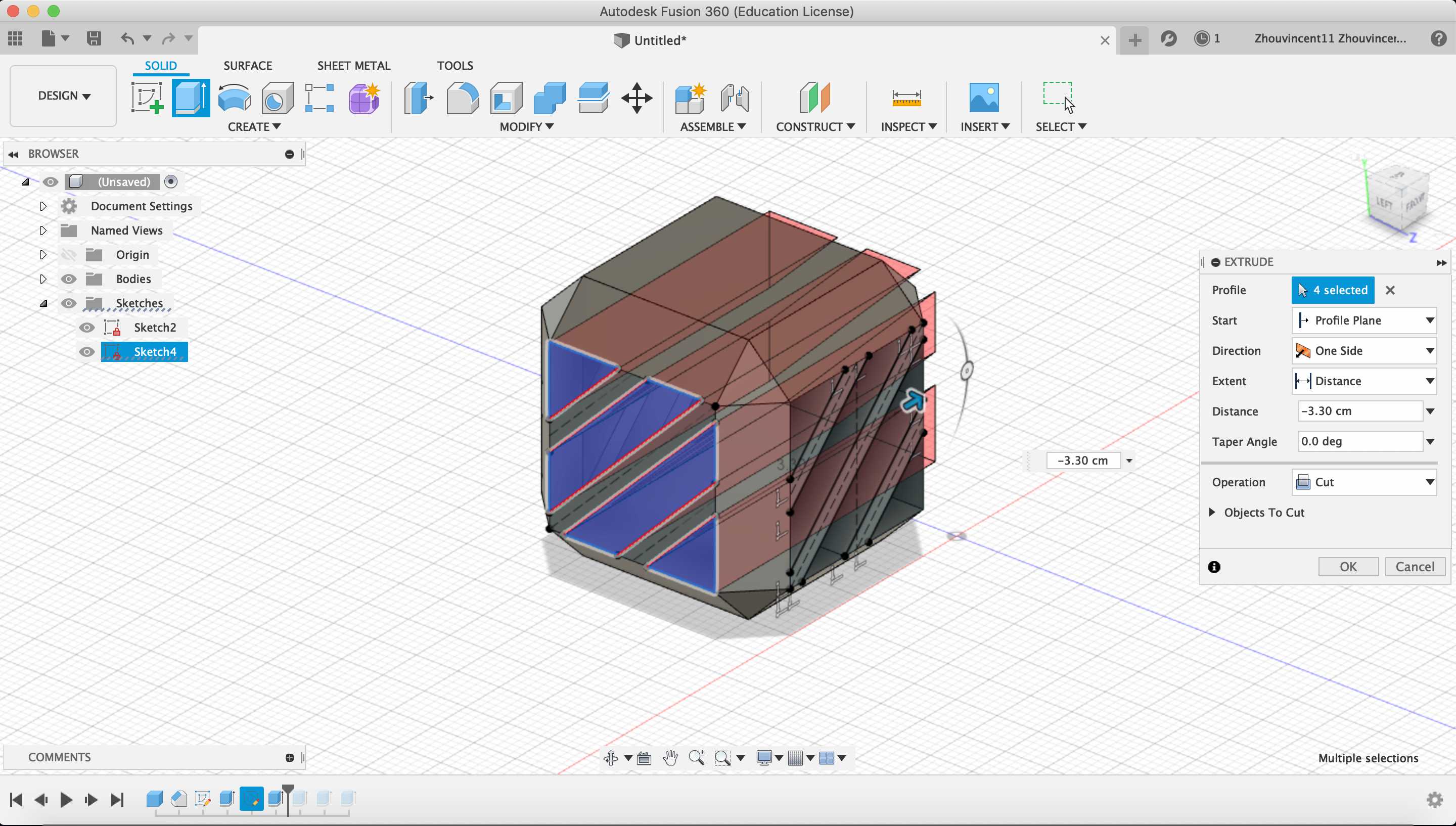
For added visbility into the box, I extruded the top of the box out.
Print
I exported the Fusion 360 model as an .stl and imported the file into Cura, a slicing software. I scaled the model by 1000% on all axes because Cura imported the model in millimeters instead of centimeters. Then, I rotated the model on the x-axis by 90º to make the opening of the box face upwards.
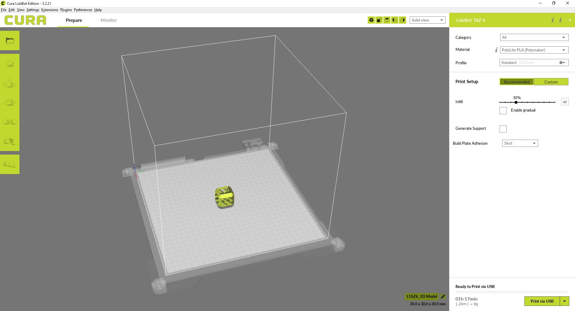
After manipulating the model, I pressed the “Print via USB” button to begin the print. Here are images of the print:
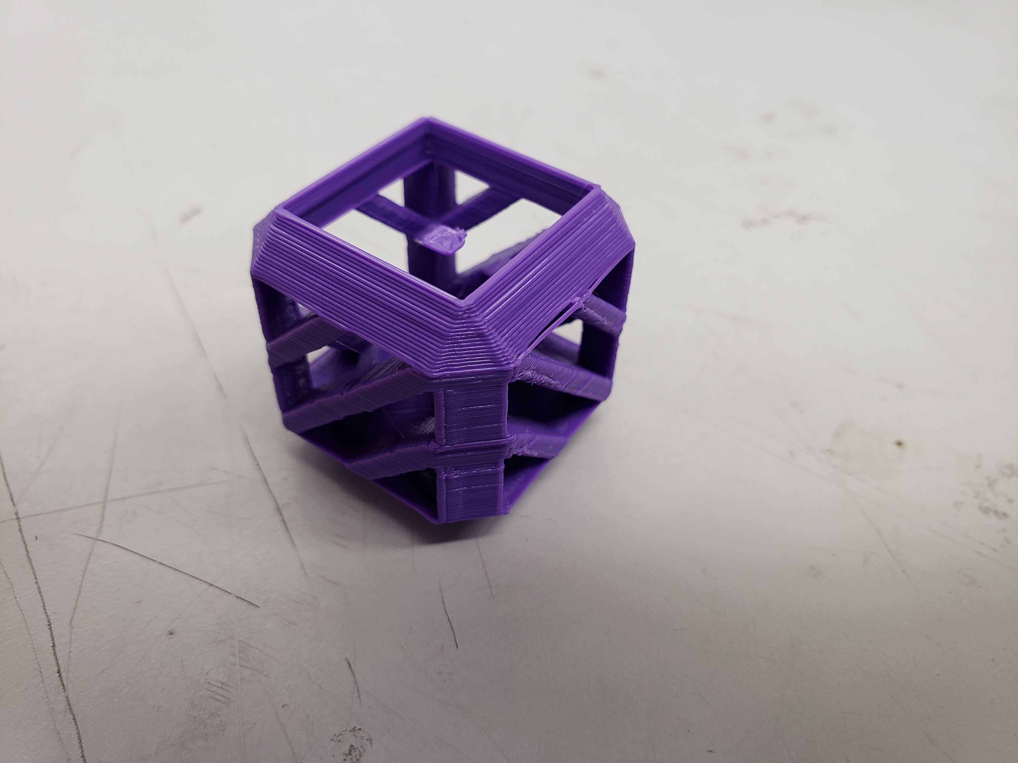
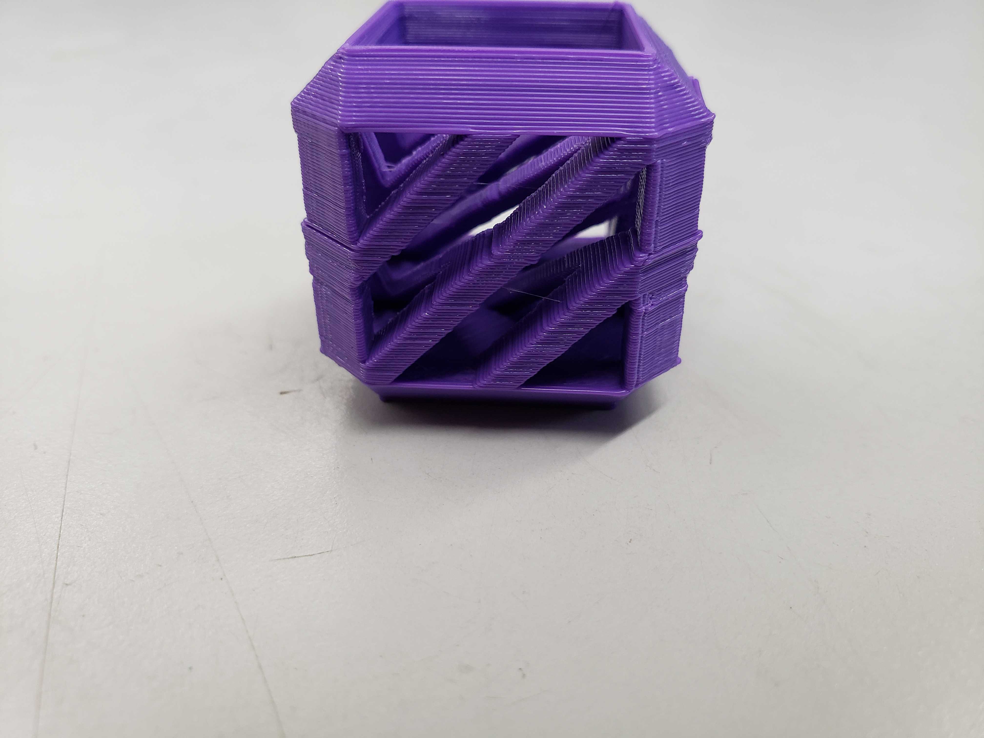
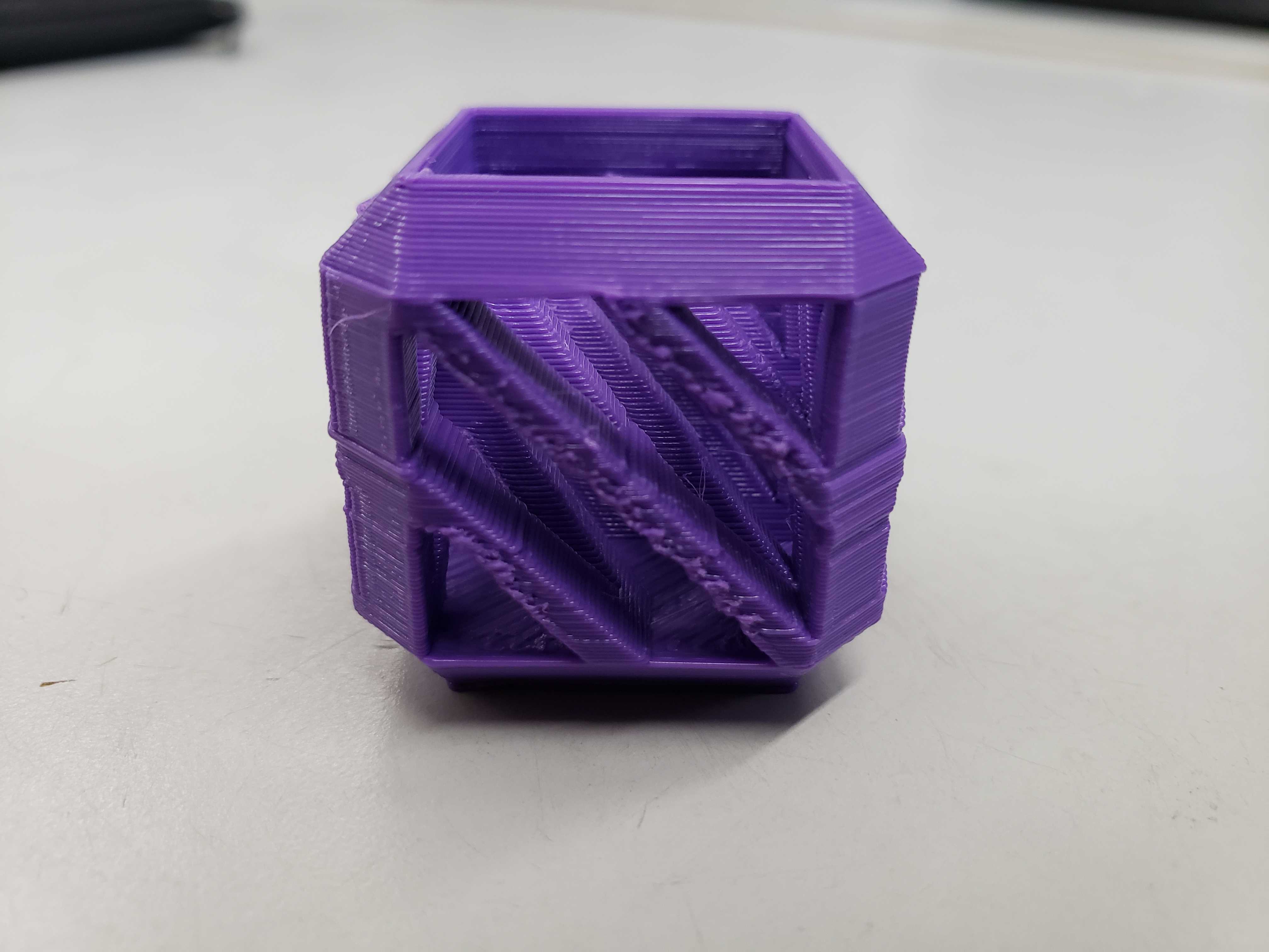
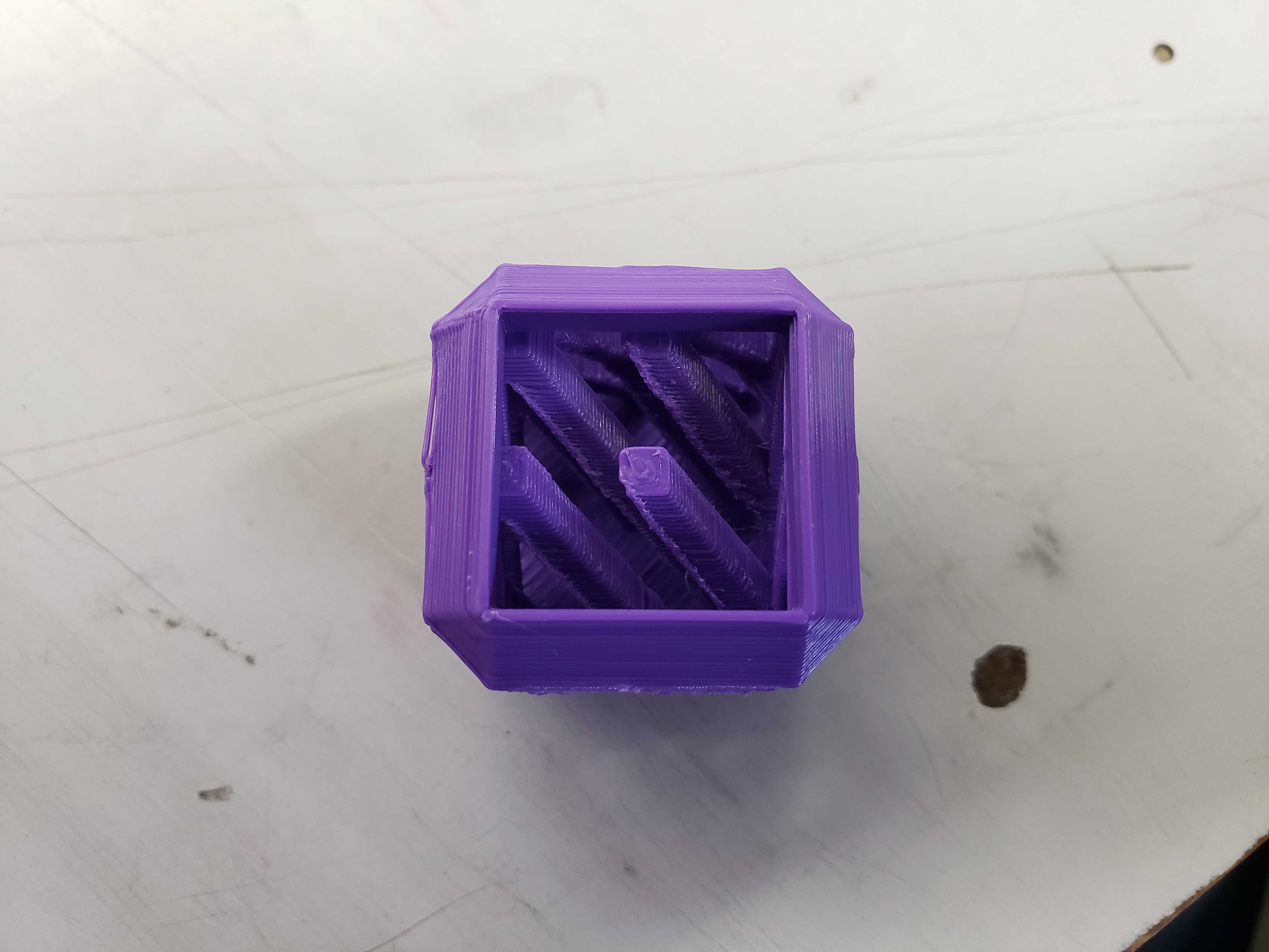
Strangely enough, the print had rough edges facing one direction throughout the entire model. In addition, the print seemed to shift midway through the print. These were probably problems that could have been solved by changing print settings.
3D Scanning
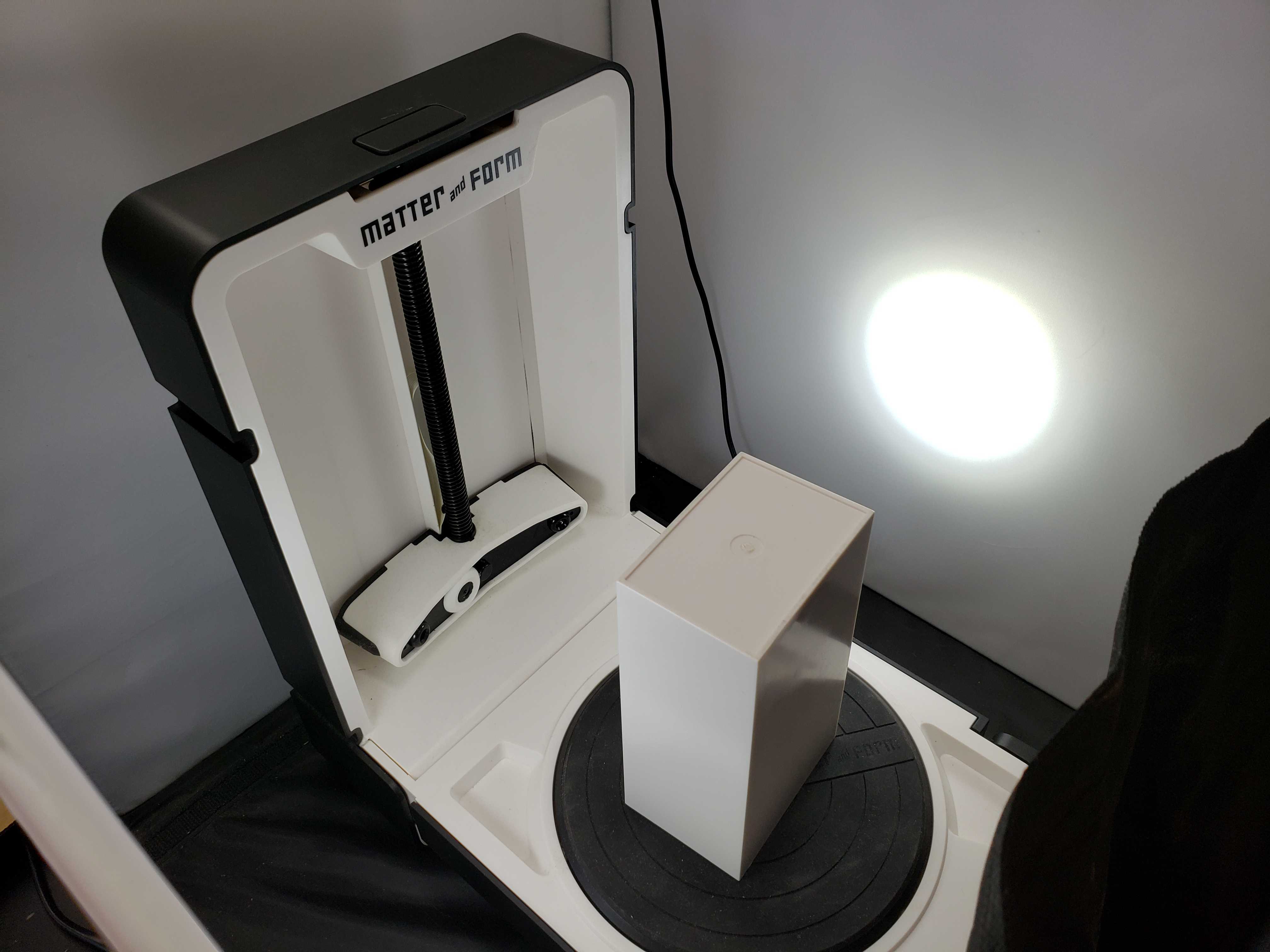
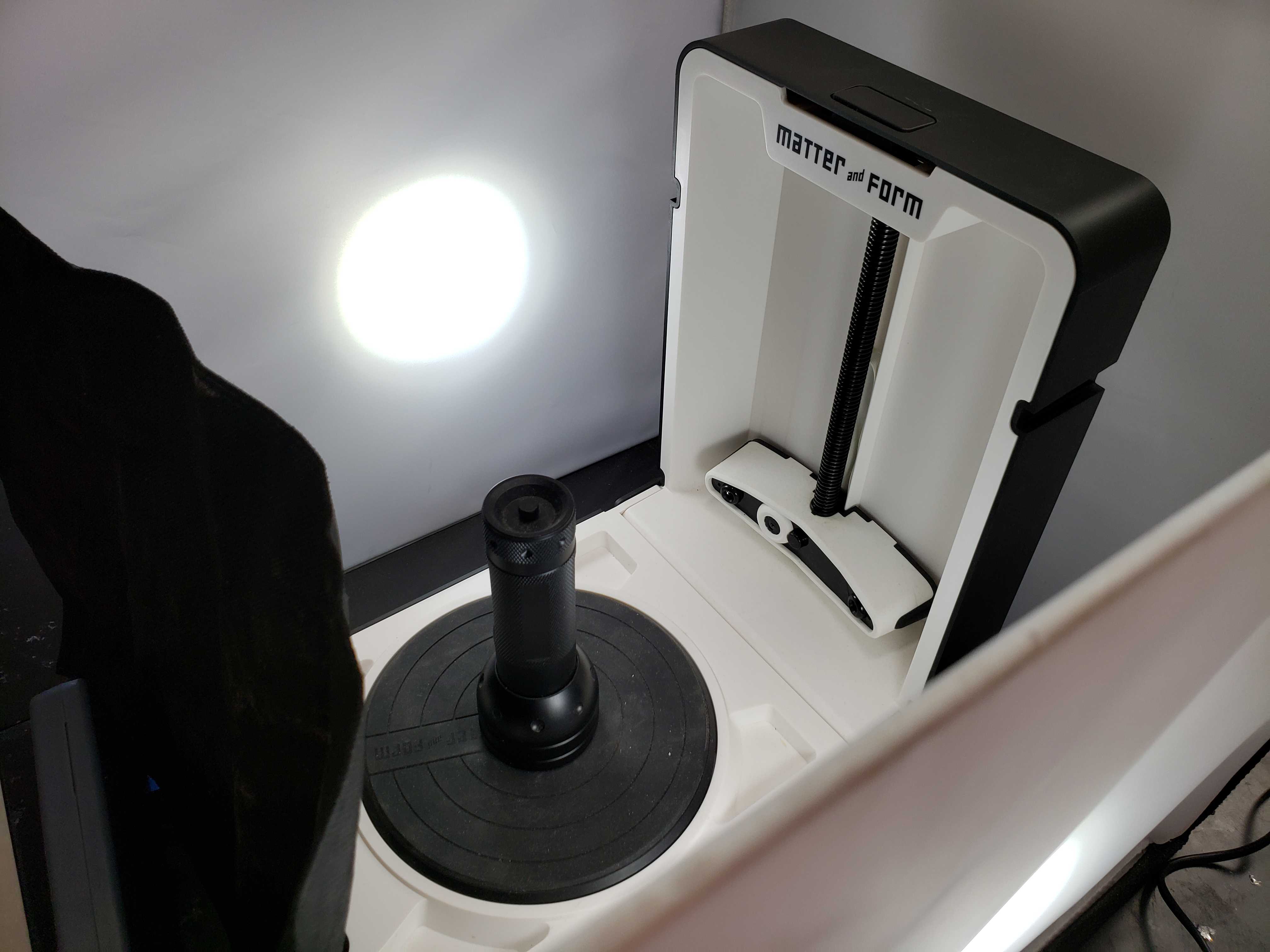
The lab had a Matter and Form 3D scanner available for use, so I decided to give it a try.
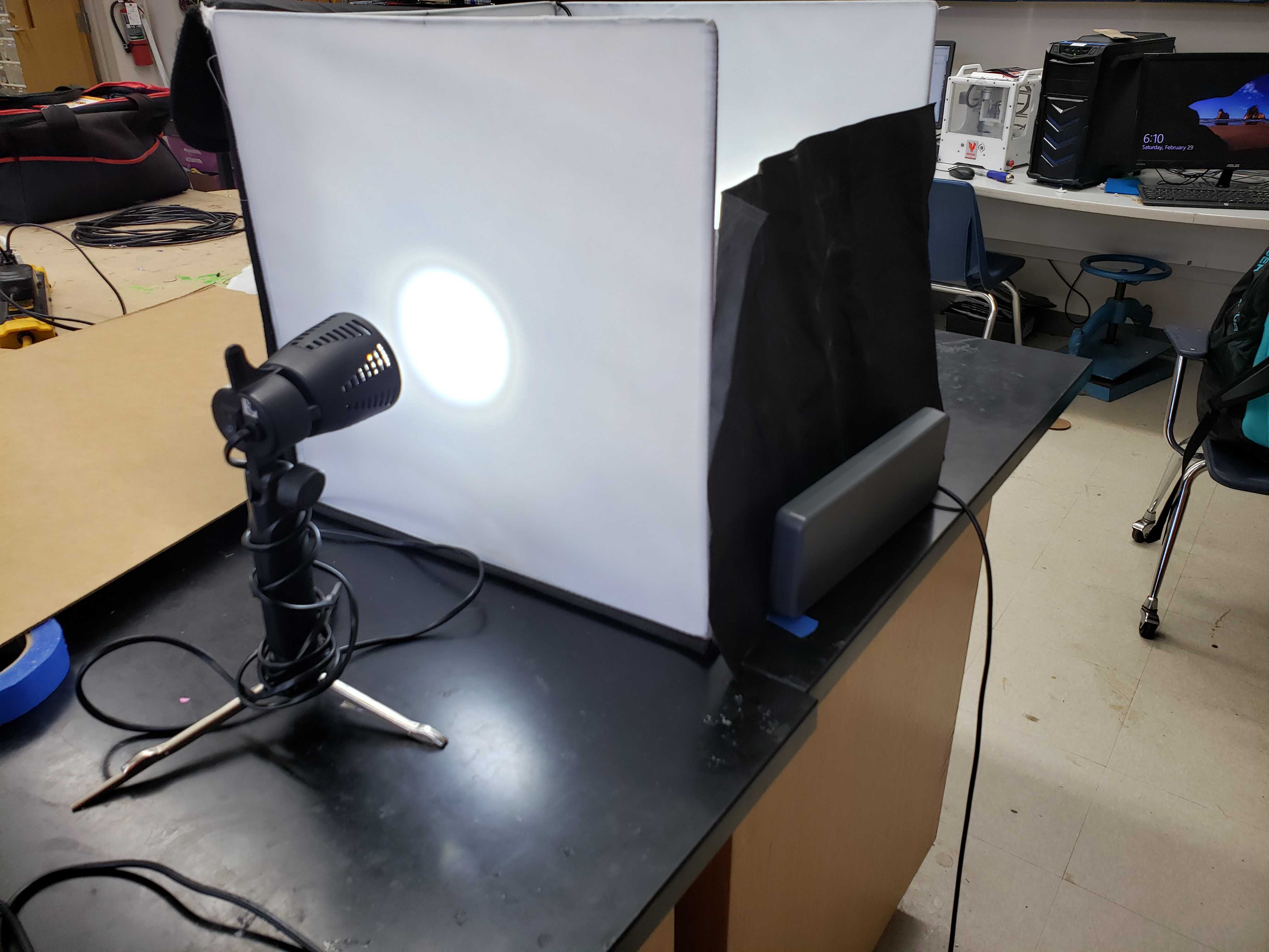
First, I setup and lit a lighting booth to provide adequate ambient lighting for accurate scans.
Next, I calibrated the scanner by placing the calibration box in the middle of the turning plate and clicking on the “Calibrate” button in MFStudio
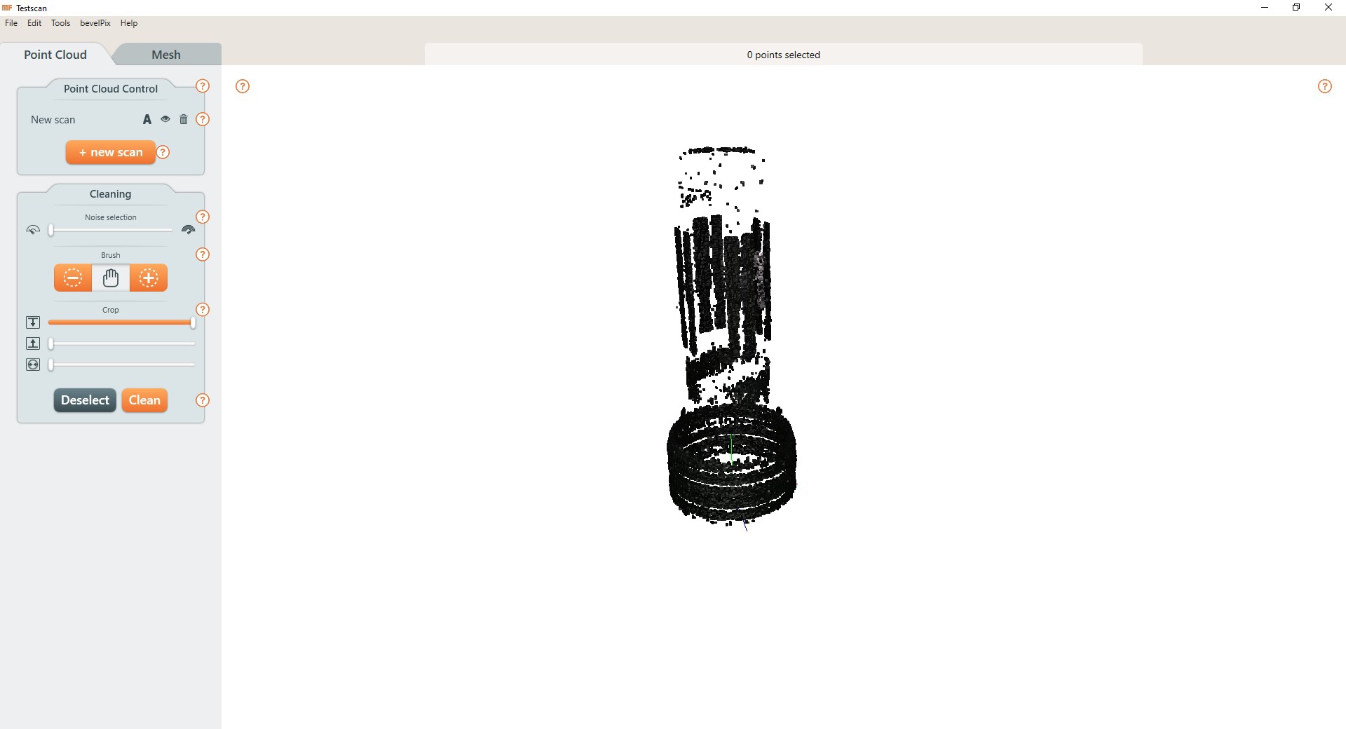
Now, the scanner was ready. I placed a flashlight in the middle of the plate, changed the height settings to reflect the height of the flashlight, and pressed scan. The scan took about 1 hour due to the height of the flashlight.
Unfortunately, I failed to account for the reflectivity of the metal and the rugged texture of the grip. As a result, the scan failed to capture several sections of the flashlight.
I decided to use 3D scan Harri’s puzzle piece as it was less reflective, small and stil relatively simple.
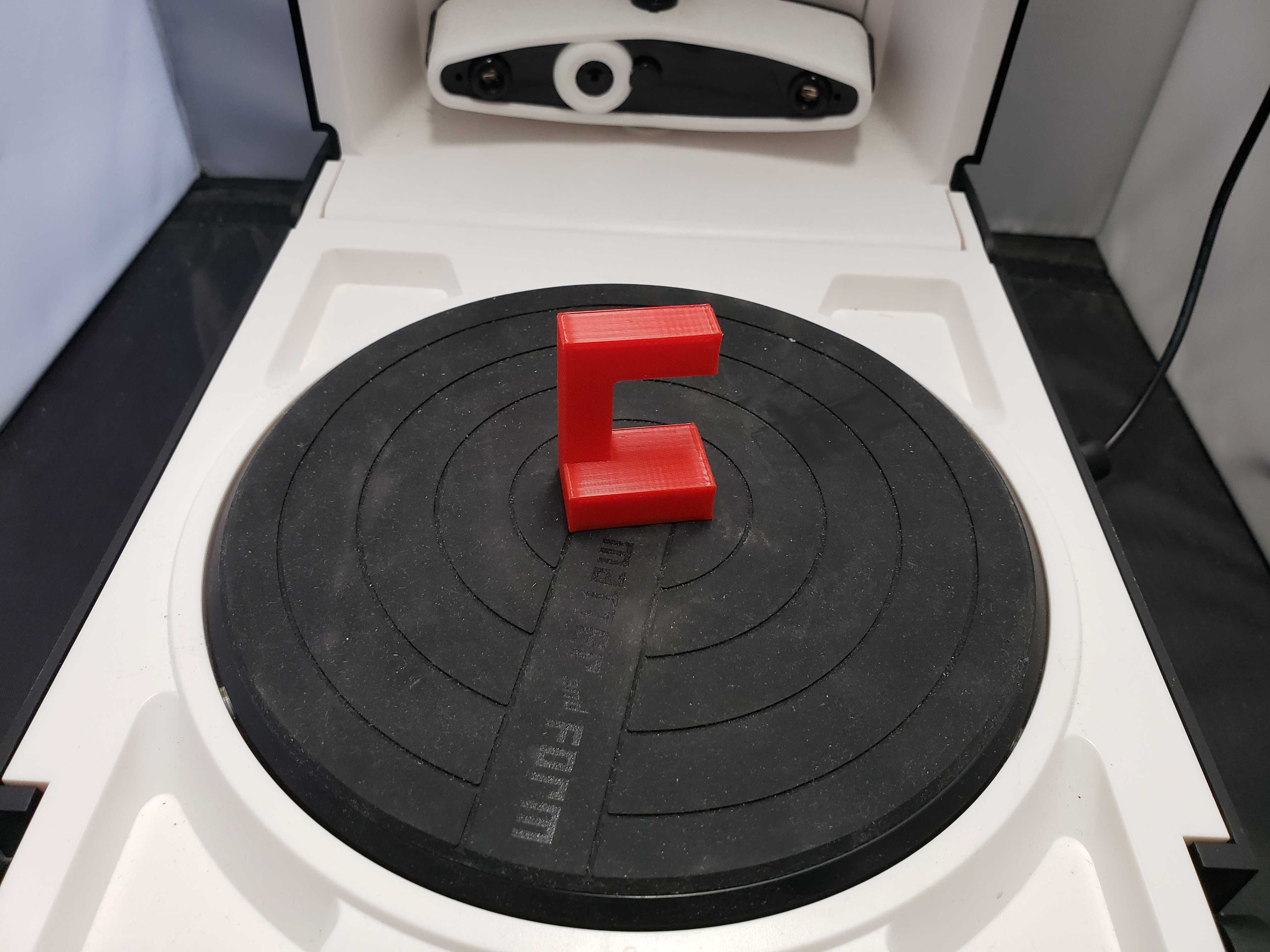
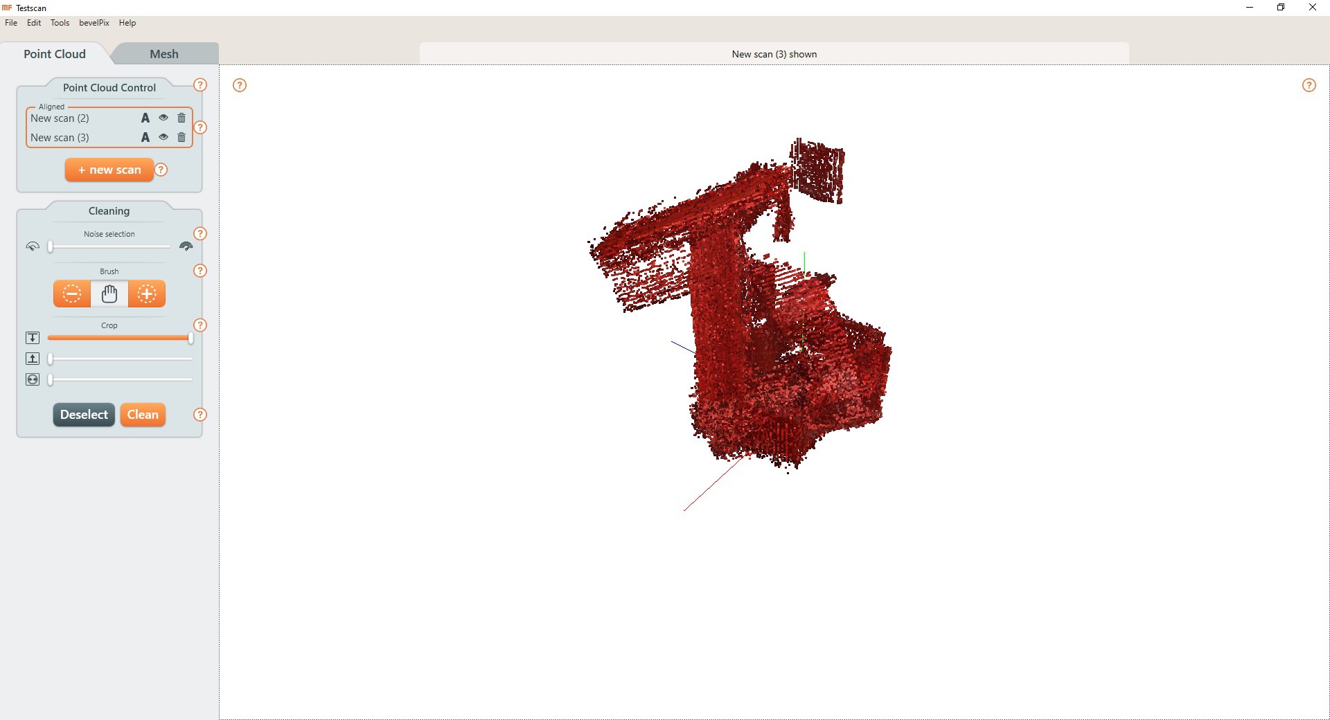
However, the non-symmetrical geometry of the peice and the limitations of the 3D scanner meant that major portions of the piece were not captured. I attempted to rectify the problems by scanning the piece in a new orientations and merging the scans, but the merge failed catastrophically.
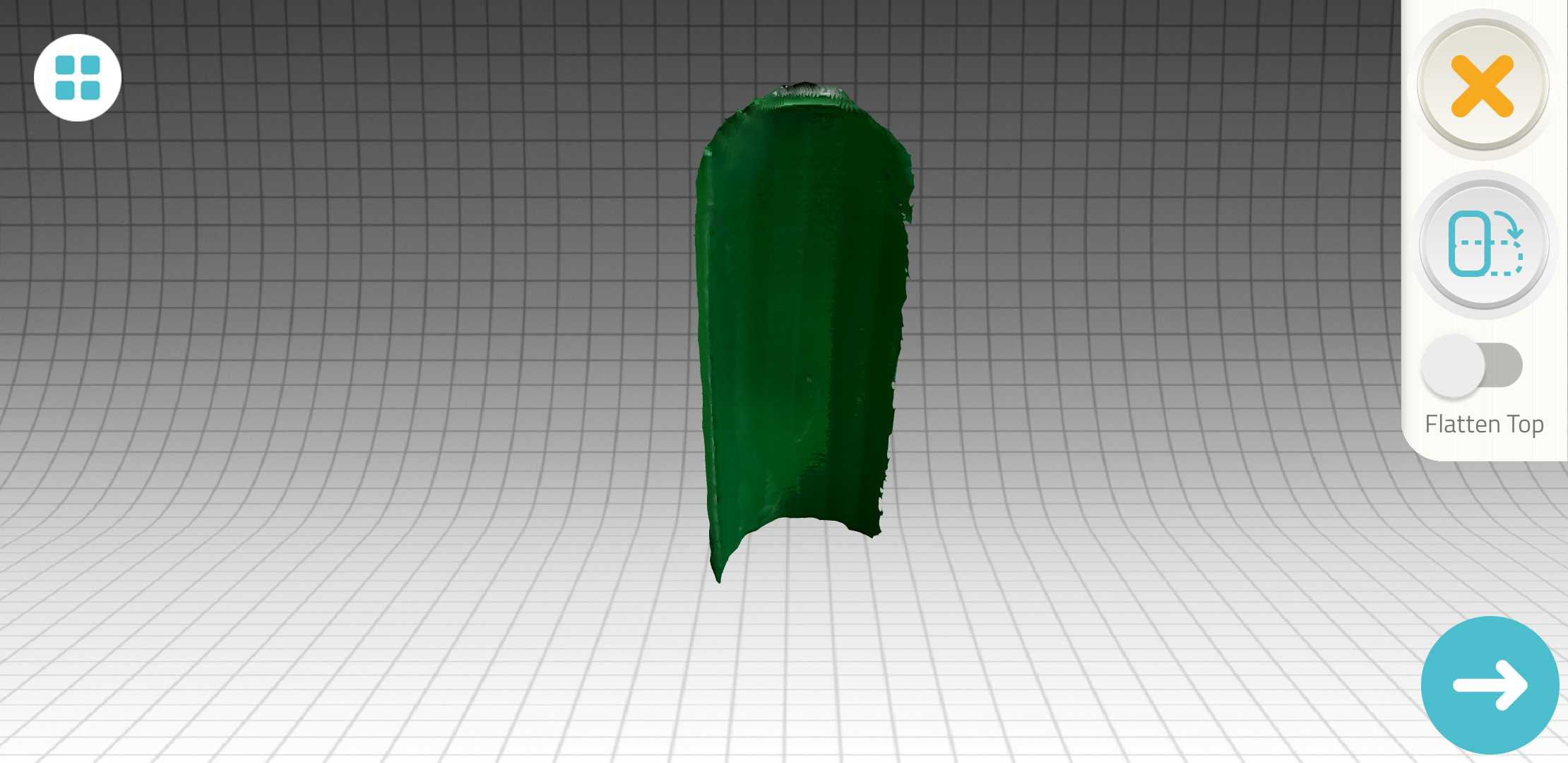
Due to these failures, I took Mr. Rudolph’s suggestions and looked into 3D scanning apps instead. I used an app called “Qlone” that other Fab Academy students have used. The app uses printed markers on paper to determine camera orientation. I tried the app on a spare 3D print to test out the app’s capabilities.
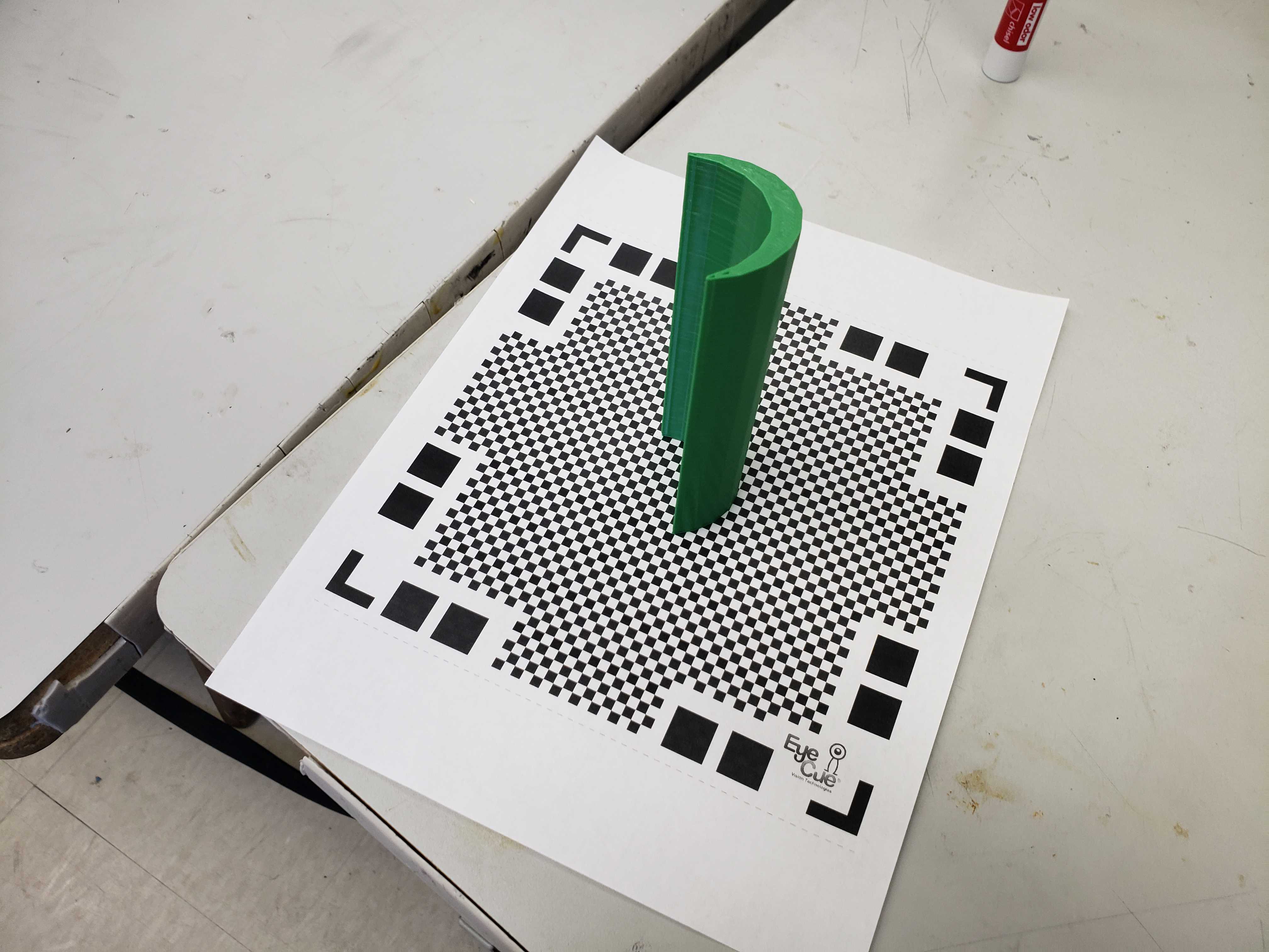
The scan was quite rugged, but it performed better than the Matter & Form scanner.
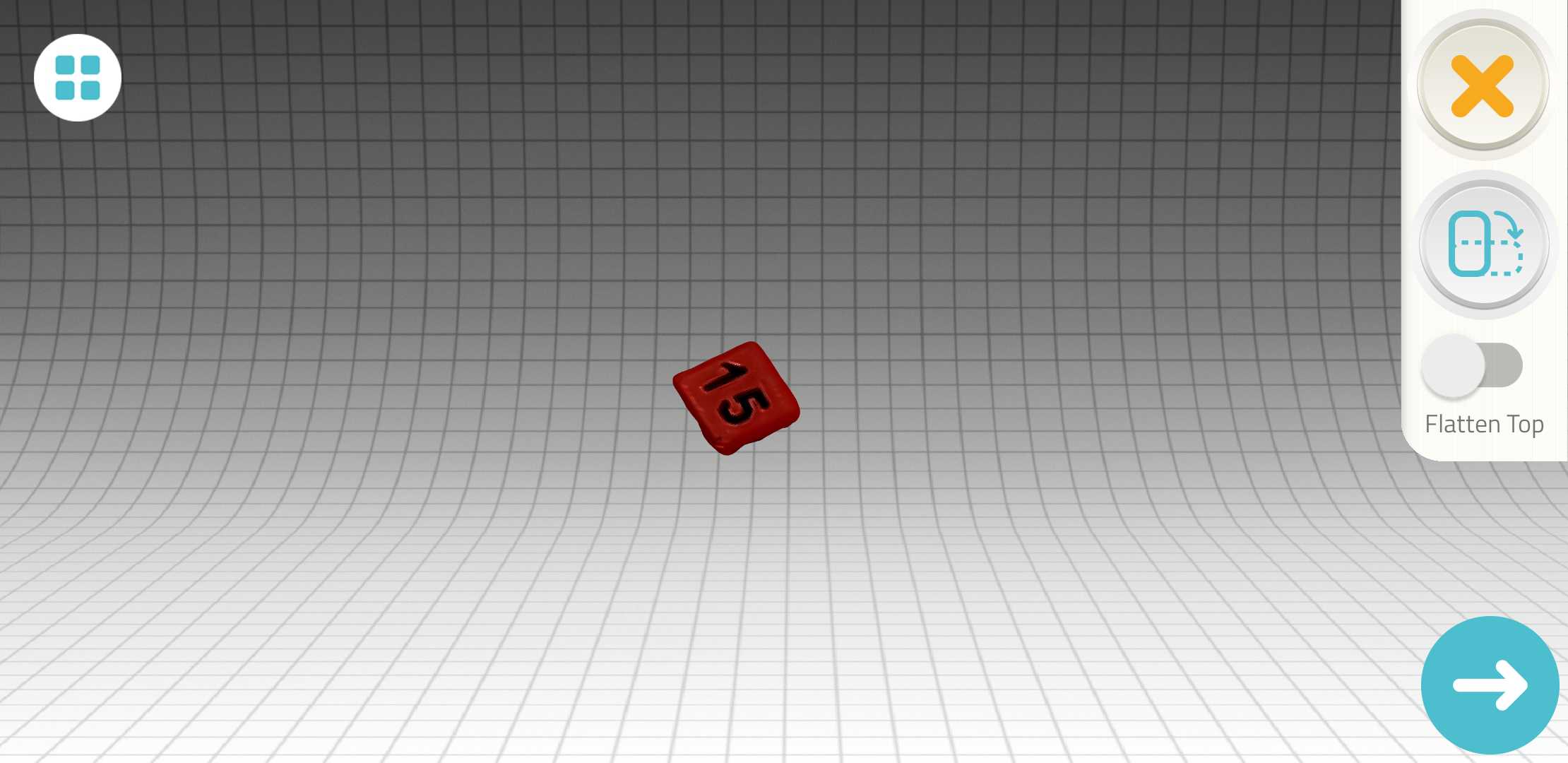
I tried again with a simple cube to see the baseline accuracy.
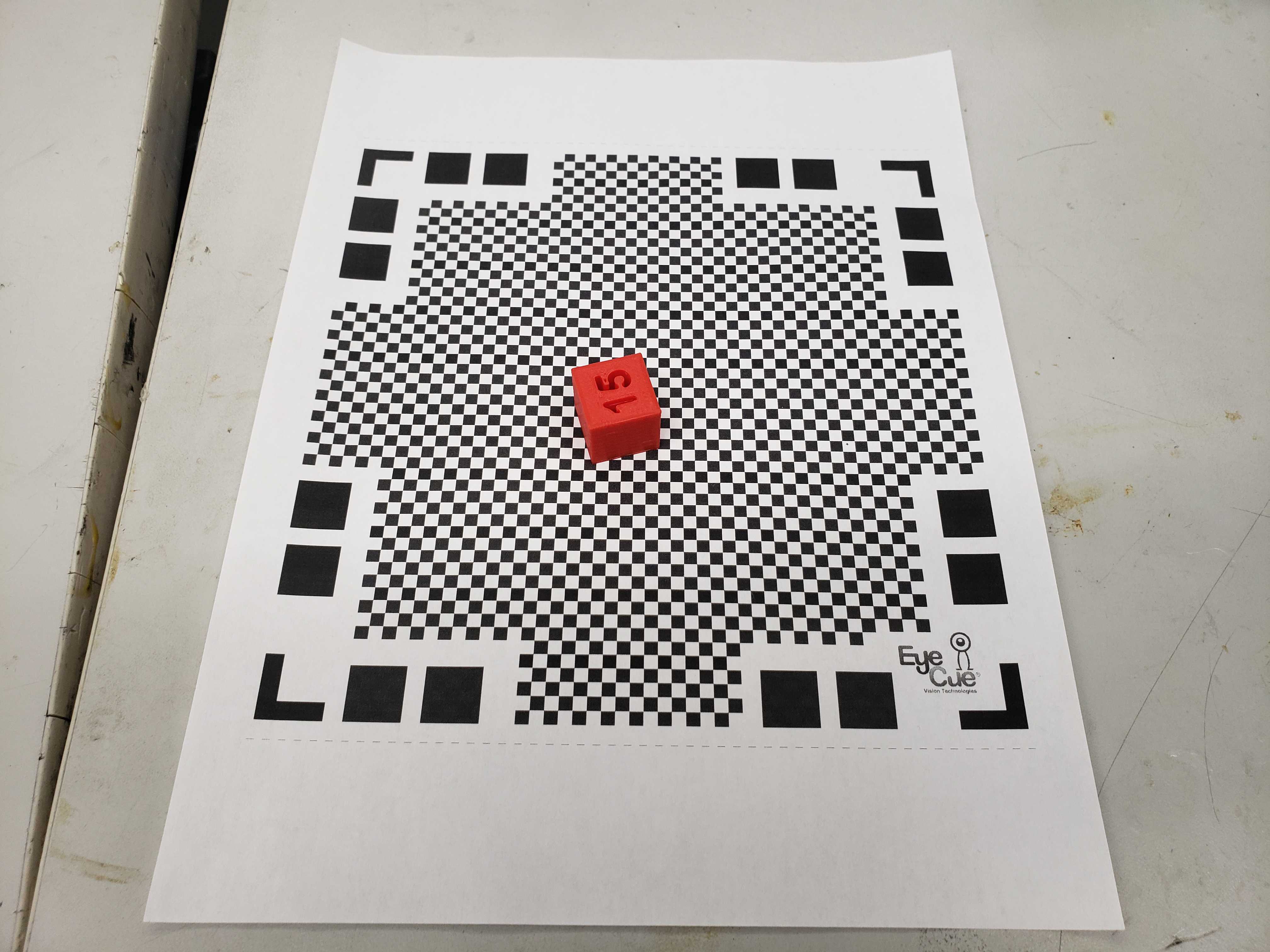
Even then, the cube turned out very rough. However, I didn’t expect very much accuracy from a purely optical scanner.