10. Input Devices
This week’s assignment:
Group assignment
Probe an input device(s)'s analog and digital signals
Document your work (in a group or individually)
Individual assignment
Measure something: add a sensor to a microcontroller board that you have designed and read it.
Basic Research
I know I will need to make an IMU input sensor to start working towards the acceleration, orientation, and rotation measurements I will need to make a self-balancing ball. So, that is what I will be building here.
I started the work by doing some research.
I knew the general concept of accelerometers and gyroscopes. They are sensors that measure acceleration and rotation. I was able to do more research on defining what they are and how they work this week.
Accelerometers: Measure the change in velocity (acceleration) in m/s^2 of G-forces (1g = 9.8 m/s^2)
This gif helps with visualization. A small object is surrounded by a special material called piezoelectric sensors. These piezoelectric sensors produce voltage when they are bumped into/ touched in some way. The voltage produced varies. A small ball is placed with lots of space around these sensors, and when the object is moved the ball on the inside moves in a predictable way. The voltage can be interpreted to give us information about where the ball has moved, and with that information we can figure out where the larger object being measured by the ball has moved. source
There are also gyroscopes, which are often confused with an accelerometer, measures orientation based on gravity. Gyroscopes measure the rate of rotation around a particular axis (an axis that points “down” towards the center of the earth.) They are very similar. source
When combined, they provide a lot of information about the position of an object. Many devices combine these position-detecting technologies. These are called IMU’s. The combined data is better than one alone. The IMU I am using (the MPU-6050) has 6 different types of measurements. It is meant to give ore data, but some people find IMU’s less efficient than just one board.
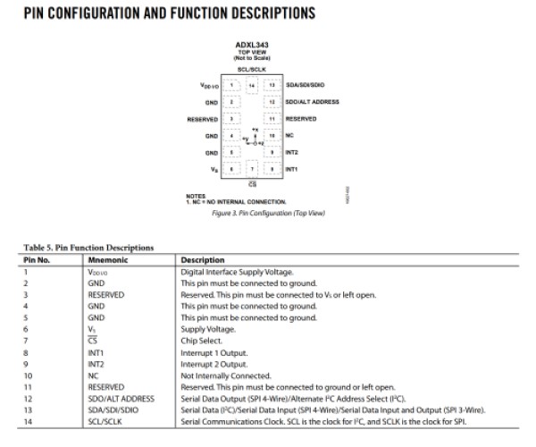
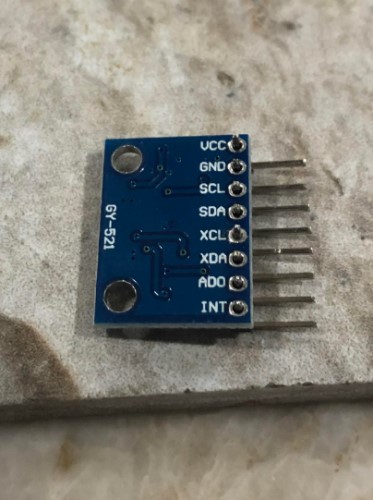
The component Niel suggests is a ADXL343BCCZ accelerometer. We don’t have this part at our lab currently, and Mecklenberg is under a stay at home order, so for now I will work with an MPU-6050 (functions described on pages 10-11). We already had this device in the lab. My biggest fear is that this seems to be a breakout board, not just the original component. I doesn’t really know
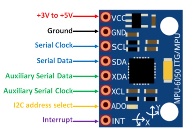
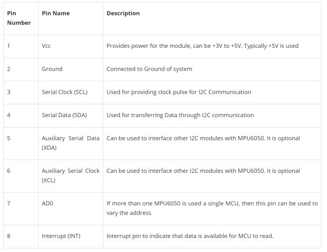
Above is the MPU-6050 pinout.
I found lots of sites teaching me how to interface the board with arduino and what the code would look like for that. They were fun to explore to teach me how arduino worked. This source described the code a lot better. redraw in tinkercad **add basic code. Commented?? Comment used code later
Designing the Board
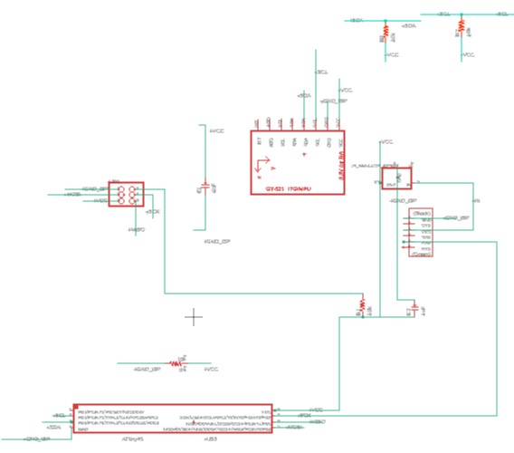
The board schematic Niel attached is as found below:
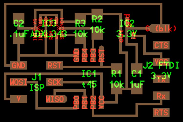
I tried to reference his design for my board, but board schematic files often have a lot of things abbreviated, so I referenced the component’s pinout for more detailed pin descriptions. I found this on the component’s datasheet
When comparing the fab academy example board’s schematic to the pinout, I spent a lot of time trying to make sure I had connected everything to the correct position. I included a photo of my notes below.

I also used this source because it gave a pretty clear block diagram of the interior workings with an explanation. It seems like the block includes an accelerometer chip on its own, so I am trying to figure out where the accelerometer pins attach to the GPU pins I can interface with.
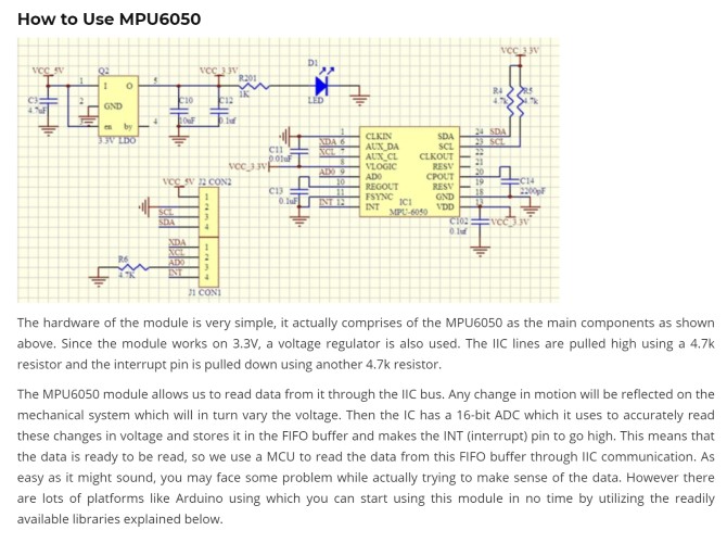
My biggest problems came from trying to figure out what the MPU6050 XDA, XCL and ADO pins were “equivalent” to on the AX… example board.” There were also more AX… pins than there were MPU6050 pins being used.
Note: I downloaded my MPU-6050 component from this library
I ended up with this:

But this was incredibly messy and I still had a lot of questions. I talked to my teacher Mr. Rudolph, and he helped explain a lot of the pins and what was necessary and what wasn’t. I hadn’t used a lot of the connections on the breakout board (MPU) device, but I knew I still had connections from Niel’s example board that I was missing. The most vital pins seem to be VCC and Ground (of which there are multiple on the AX… chip in the example that I just combined) and the SDA and SCL pins, which will allow the board to communicate via I^2C.
Mr. Rudolph also showed me I was missing a “trace” between the VCC coming from the attiny and ground, and that I also needed a capacitor between these parts. He also showed me a cool way to name the traces using the “Value” tool and the program will know that traces with the same value are meant to be connected. I left a couple of the normal wires in (without the naming trick) because I found it a little easier to visualize. I ran an ERC at the end to make sure there were no errors that this tool would pick up. Here is my second iteration of the schematic:
Because Mecklenberg is under a stay at home order from COVID-19, I wanted to make sure I milled my board right the first time, so I did a lot of research and double checking connections. Hopefully my design will work on the first try.
After I got it back, I then went to route my board. I routed it normally. I do have a through hole component, Mr. Rudolph suggested that I put it on the other side of my board to save space. My plan is to do that. With these considerations in mind, here is my board fully routed.

I talked to Mr. Rudolph again, and at this point we had confiemd the spefici part in use. A couple of things ha dto be changed because the MPU-6050 has parts on the inside that i was trying to do on the outside.
Also needed to flip my component to the other siude (MPU) otherwise pins wouldn’t line up! Obviously. I figured out how to mill a board like that here
I then exported it into Bantam as three separate files(one for traces- 1/64thinch bit, outline cuts-1/32inch bt, and through-holes-1/64th inch bit) with the correct placement of the board and the correct tools for each type of and sent it to my teachers who were very nice and milled out the board for me so that I could make some progress on this. To see more about milling, refer to week05 Electronics and week07 electronics design.
Final Board:
I think my soldering has improved quite a bit. My craftsmanship seems to have improved. I was very nervous that the MPU-6050 pins didn’t have strong connections because they were on the other side and I had to force the solder to reach a tiny pin that did not really reach the pad. It seems like it is well attached, and a simple test with a multimeter demonstrated that all the connections were where they needed to be.
After I finished soldering I realized only 3 pins were connected. I had wired the VCC, GND and SCK ports to a pin, but I needed to have the VCC, GND, SCL and SDA ports connected to a pin. I cannot recut my board at this point, so I used some loose wire to connect empty pins to the SDA and SCL ports to empty pins.
I found two empty pins and attached the MPU ports to these pins. Technically, I could have used the pins on the back of the MPU, but I wanted to stick with my original board plan. It ended up looking like this:
Programming the Breakout Board
I set up my wiring according to this image from here. This was another site with similar information. I used these to tackle the MCU side of the board.
I ignored the reset pin on the MCU. The reset is a feature that could make the MPU function better but isn’t necessary.
But this was only half the equation.
I also had to deal with the attiny and the way the MPU interacted with the rest of my breakout board. The tricky thing about my board is that the MPU-6050 is its own breakout board on my breakout board. I had to make sure everything was wired in a way that was compatible. I found my tutorial for programming a normal Attiny45 board here
First I set up my arduino as a ISP programmer and programmed the attiny45. I went through the same process in week8, embedded programming week with the jtag2updi programming, so I won’t go through that part again. The differences were minimal and can be found on the site, because the process was the same.
This was my final setup:
I then compiled and uploaded the program using the Arduino programmer. Unfortunately, I got this error message:
avrdude: Device signature = 0x000000
avrdude: Yikes!  Invalid device signature.
         Double check connections and try again, or use -F to override
         this check.


avrdude done.  Thank you.
Most forums suggested that something was wired wrong, so I just kept checking until eventually I realized that I had put two 10k resistors on one wire that should only have one 10k resistor.

(RST (reset) and VCC_OUT(voltage, “out”) has resistors in two places that will connect. One is redundant. Looking at the board. I realize I definitely meant to place it as a 0k resistor, but mislabeled it as a 10k resistor. If a signal isn’t getting all the way back because there is too much resistance, there might be an issue.
I desoldered one of the 10k resistors and replaced it with a 0k resistor.
After fixing this and retrying, I was still getting the same error. At this point I had checked everything numerous times (and had finally caught that resistor) but I will continue to check connections and my diagrams. Eventually I realized I had changed the clock frequency and needed to burn the bootloader of the attiny, which I hadn’t done.
However, I was still getting the same error after burning the bootloader, which meant this wasn’t the issue.
avrdude: Device signature = 0x000000
avrdude: Yikes!  Invalid device signature.
         Double check connections and try again, or use -F to override
         this check.

avrdude: Send: Q [51]   [20]
avrdude: Recv: . [14]
avrdude: Recv: . [10]

avrdude done.  Thank you.
An arduino forum suggested I had either selected the wrong board under Tools -> Board or that I didn’t have the most recent standard version of AvrDude that Arduino uses.
I believe the error has to be with my board. But after hours of surfing the web for possible fixes and looking for errors in the wiring, I am not entirely sure what to do with it. In the interest of time, I will try to interface the arduino directly to the MPU-6050, which seems to be the MPU’s intended purpose, so that I can still learn a bit about this. I will come back to building the breakout board later, when the COVID-19 stay at home order has ended and I have access to more resources to either figure out this board or make the breakout board with the chip Neil suggested.
Programming the MPU-6050
I desoldered the MPU from the breakout board and soldered it onto a set of pins.
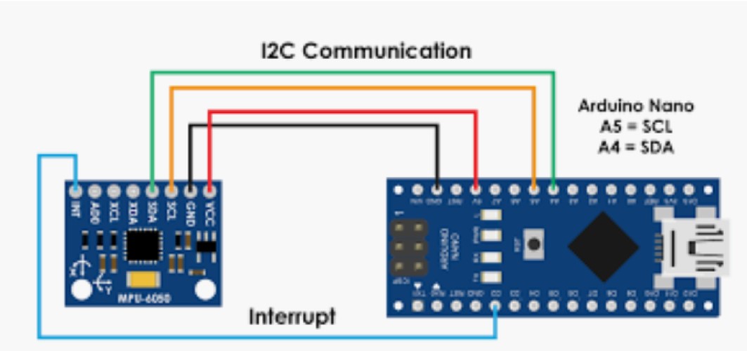
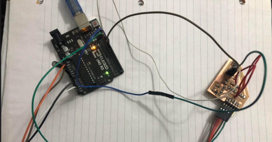
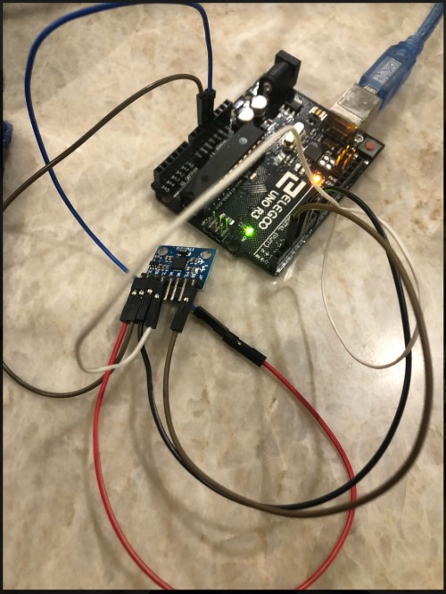
I then set up the MPU and the arduino as follows:
5v to 5v * Ground to Ground * Digital pin 2 (arduino interrupt) to MPU INT (IMU’s interrupt) pin. * Digital pin 4 (Arduino SDA) to MPU SDA pin These are the I2C communication lines * Digital pin 5 (Arduino SCL) to MPU SCL pin These are the I2C communication lines*
I then extracted the zip file for the MPU-6050 Arduino libraries in the library file folder folder for Arduino. I also extracted the I2Cdev library in the same location.
I then opened Arduino IDE. I went to File –> Examples –> MPU6050 (it’s at the very bottom of the side menu) –> Examples –> MPU6050_DMP6 and opened that sketch.
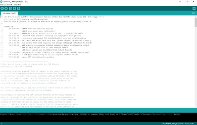
I then compiled the code, and uploaded it under all the normal settings (Tools -> Boards -> Arduino Uno, and Programmer -> ArduinoISP).
When it finished uploading it seemed successful. However it also told me that I had “unrecognized libraries” at the end with this message:
Invalid library found in C:\Users\sv285\OneDrive\Documents\Arduino\libraries\__MACOSX: no headers files (.h) found in C:\Users\sv285\OneDrive\Documents\Arduino\libraries\__MACOSX
Invalid library found in C:\Users\sv285\OneDrive\Documents\Arduino\libraries\__MACOSX: no headers files (.h) found in C:\Users\sv285\OneDrive\Documents\Arduino\libraries\__MACOSX
I’m assuming I accidentally downloaded MAC libraries instead of windows libraries. I just moved them out of the way so the IDE wouldn’t confuse them (if that’s possible), because I saw that separate windows libraries had been installed as well, recompiled and uploaded the code, and the error message went away.
I then opened The serial monitor and set the baud rate to 115200.
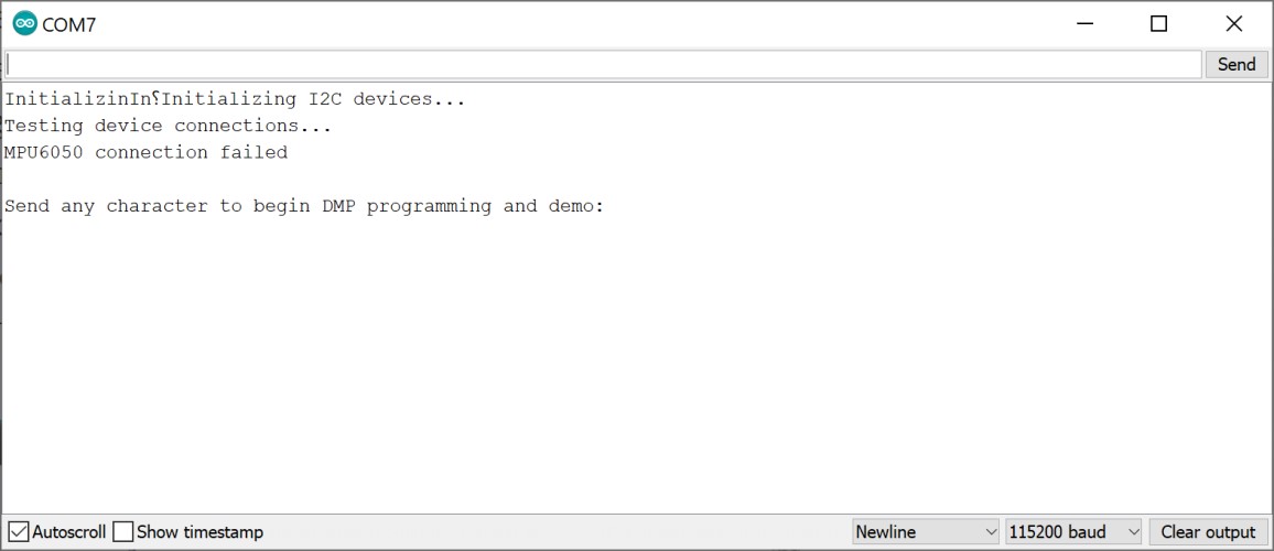
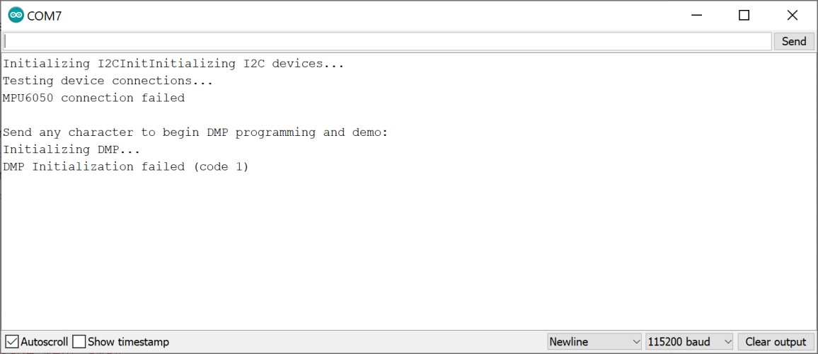
It said that the connection failed. When I tried to type in characters, I got more error messages.
I troubleshooted for a while, then stumbled upon a much simpler guide which was more straightforward and provided a much better explanation of the code used.
It simply needed the 5v pin going to the 5v pin, * Ground to Ground * Digital pin 4 (Arduino SDA) to MPU SDA pin These are the I2C communication lines * Digital pin 5 (Arduino SCL) to MPU SCL pin These are the I2C communication lines*
It used this code and had a very simple description that I used to comment into the code and explain what each section was doing:
/*
   Arduino and MPU6050 Accelerometer and Gyroscope Sensor Tutorial
   by Dejan, https://howtomechatronics.com
*/
#include <Wire.h>
const int MPU = 0x68; // MPU6050 I2C address
float AccX, AccY, AccZ;
float GyroX, GyroY, GyroZ;
float accAngleX, accAngleY, gyroAngleX, gyroAngleY, gyroAngleZ;
float roll, pitch, yaw;
float AccErrorX, AccErrorY, GyroErrorX, GyroErrorY, GyroErrorZ;
float elapsedTime, currentTime, previousTime;
int c = 0;
void setup() {
  Serial.begin(19200);
  Wire.begin();                      // Initialize comunication
  Wire.beginTransmission(MPU);       // Start communication with MPU6050 // MPU=0x68
  Wire.write(0x6B);                  // Talk to the register 6B
  Wire.write(0x00);                  // Make reset - place a 0 into the 6B register
  Wire.endTransmission(true);        //end the transmission
  /*
  // Configure Accelerometer Sensitivity - Full Scale Range (default +/- 2g)
  Wire.beginTransmission(MPU);
  Wire.write(0x1C);                  //Talk to the ACCEL_CONFIG register (1C hex)
  Wire.write(0x10);                  //Set the register bits as 00010000 (+/- 8g full scale range)
  Wire.endTransmission(true);
  // Configure Gyro Sensitivity - Full Scale Range (default +/- 250deg/s)
  Wire.beginTransmission(MPU);
  Wire.write(0x1B);                   // Talk to the GYRO_CONFIG register (1B hex)
  Wire.write(0x10);                   // Set the register bits as 00010000 (1000deg/s full scale)
  Wire.endTransmission(true);
  delay(20);
  */
  // Call this function if you need to get the IMU error values for your module
  calculate_IMU_error();
  delay(20);
}
void loop() {
  // === Read acceleromter data === //
  Wire.beginTransmission(MPU);
  Wire.write(0x3B); // Start with register 0x3B (ACCEL_XOUT_H)
  Wire.endTransmission(false);
  Wire.requestFrom(MPU, 6, true); // Read 6 registers total, each axis value is stored in 2 registers
  //For a range of +-2g, we need to divide the raw values by 16384, according to the datasheet
  AccX = (Wire.read() << 8 | Wire.read()) / 16384.0; // X-axis value
  AccY = (Wire.read() << 8 | Wire.read()) / 16384.0; // Y-axis value
  AccZ = (Wire.read() << 8 | Wire.read()) / 16384.0; // Z-axis value
  // Calculating Roll and Pitch from the accelerometer data
  accAngleX = (atan(AccY / sqrt(pow(AccX, 2) + pow(AccZ, 2))) * 180 / PI) - 0.58; // AccErrorX ~(0.58) See the calculate_IMU_error()custom function for more details
  accAngleY = (atan(-1 * AccX / sqrt(pow(AccY, 2) + pow(AccZ, 2))) * 180 / PI) + 1.58; // AccErrorY ~(-1.58)
  // === Read gyroscope data === //
  previousTime = currentTime;        // Previous time is stored before the actual time read
  currentTime = millis();            // Current time actual time read
  elapsedTime = (currentTime - previousTime) / 1000; // Divide by 1000 to get seconds
  Wire.beginTransmission(MPU);
  Wire.write(0x43); // Gyro data first register address 0x43
  Wire.endTransmission(false);
  Wire.requestFrom(MPU, 6, true); // Read 4 registers total, each axis value is stored in 2 registers
  GyroX = (Wire.read() << 8 | Wire.read()) / 131.0; // For a 250deg/s range we have to divide first the raw value by 131.0, according to the datasheet
  GyroY = (Wire.read() << 8 | Wire.read()) / 131.0;
  GyroZ = (Wire.read() << 8 | Wire.read()) / 131.0;
  // Correct the outputs with the calculated error values
  GyroX = GyroX + 0.56; // GyroErrorX ~(-0.56)
  GyroY = GyroY - 2; // GyroErrorY ~(2)
  GyroZ = GyroZ + 0.79; // GyroErrorZ ~ (-0.8)
  // Currently the raw values are in degrees per seconds, deg/s, so we need to multiply by sendonds (s) to get the angle in degrees
  gyroAngleX = gyroAngleX + GyroX * elapsedTime; // deg/s * s = deg
  gyroAngleY = gyroAngleY + GyroY * elapsedTime;
  yaw =  yaw + GyroZ * elapsedTime;
  // Complementary filter - combine acceleromter and gyro angle values
  roll = 0.96 * gyroAngleX + 0.04 * accAngleX;
  pitch = 0.96 * gyroAngleY + 0.04 * accAngleY;

  // Print the values on the serial monitor
  Serial.print(roll);
  Serial.print("/");
  Serial.print(pitch);
  Serial.print("/");
  Serial.println(yaw);
}
void calculate_IMU_error() {
  // We can call this funtion in the setup section to calculate the accelerometer and gyro data error. From here we will get the error values used in the above equations printed on the Serial Monitor.
  // Note that we should place the IMU flat in order to get the proper values, so that we then can the correct values
  // Read accelerometer values 200 times
  while (c < 200) {
    Wire.beginTransmission(MPU);
    Wire.write(0x3B);
    Wire.endTransmission(false);
    Wire.requestFrom(MPU, 6, true);
    AccX = (Wire.read() << 8 | Wire.read()) / 16384.0 ;
    AccY = (Wire.read() << 8 | Wire.read()) / 16384.0 ;
    AccZ = (Wire.read() << 8 | Wire.read()) / 16384.0 ;
    // Sum all readings
    AccErrorX = AccErrorX + ((atan((AccY) / sqrt(pow((AccX), 2) + pow((AccZ), 2))) * 180 / PI));
    AccErrorY = AccErrorY + ((atan(-1 * (AccX) / sqrt(pow((AccY), 2) + pow((AccZ), 2))) * 180 / PI));
    c++;
  }
  //Divide the sum by 200 to get the error value
  AccErrorX = AccErrorX / 200;
  AccErrorY = AccErrorY / 200;
  c = 0;
  // Read gyro values 200 times
  while (c < 200) {
    Wire.beginTransmission(MPU);
    Wire.write(0x43);
    Wire.endTransmission(false);
    Wire.requestFrom(MPU, 6, true);
    GyroX = Wire.read() << 8 | Wire.read();
    GyroY = Wire.read() << 8 | Wire.read();
    GyroZ = Wire.read() << 8 | Wire.read();
    // Sum all readings
    GyroErrorX = GyroErrorX + (GyroX / 131.0);
    GyroErrorY = GyroErrorY + (GyroY / 131.0);
    GyroErrorZ = GyroErrorZ + (GyroZ / 131.0);
    c++;
  }
  //Divide the sum by 200 to get the error value
  GyroErrorX = GyroErrorX / 200;
  GyroErrorY = GyroErrorY / 200;
  GyroErrorZ = GyroErrorZ / 200;
  // Print the error values on the Serial Monitor
  Serial.print("AccErrorX: ");
  Serial.println(AccErrorX);
  Serial.print("AccErrorY: ");
  Serial.println(AccErrorY);
  Serial.print("GyroErrorX: ");
  Serial.println(GyroErrorX);
  Serial.print("GyroErrorY: ");
  Serial.println(GyroErrorY);
  Serial.print("GyroErrorZ: ");
  Serial.println(GyroErrorZ);
I compiled and uploaded it without running into any issues. However, when I opened the serial monitor all that displayed was never-ending question marks.
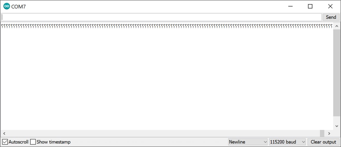
After playing with the baud rates I discovered that 9600 baud produces the prettiest emojis
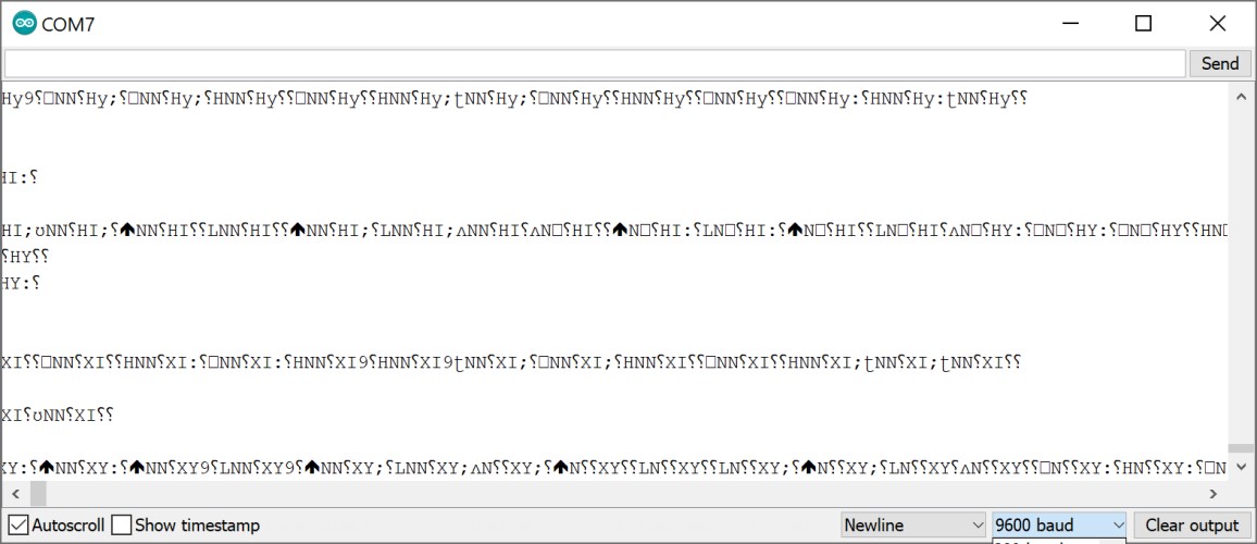
But 19200 baud produces the results we actually want.
The video got a little long fairly quickly, I started slowing down the rate at which I moved the MPU because I noticed there was a bit of a delay. This could be a problem later. I believe toggling the interrupt pin will help this.
I wanted to be able to display the results in a visual way. I downloaded Processing and copied this code into it:
It seems even slower when it is turning like this, but it is moving. This alone probably will not be a viable option for my project, but I hope to build on this and improve it.

(Processing doesn’t show most of the data, but it does display the pitch and roll of the object. You can see that it reached the position I had moved it to in the video, but this photo was taken a significant number of seconds later.
ADXL343 board
The adxl343 is the traditional chip people use when doing this week, and unfortunately it took a while to arrive for our lab, but I got it by networking and communications week. I documented my work in making the board here, but my work in programming is on this site.
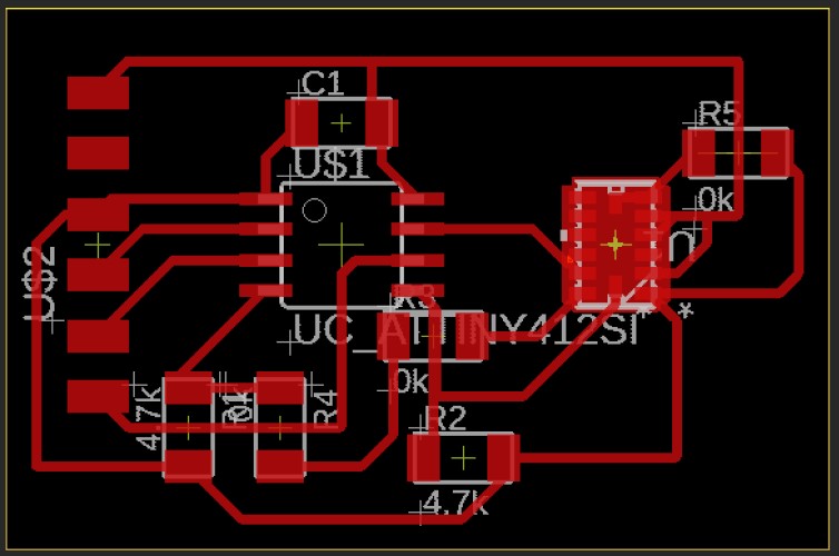
Here is a picture of the .brd:
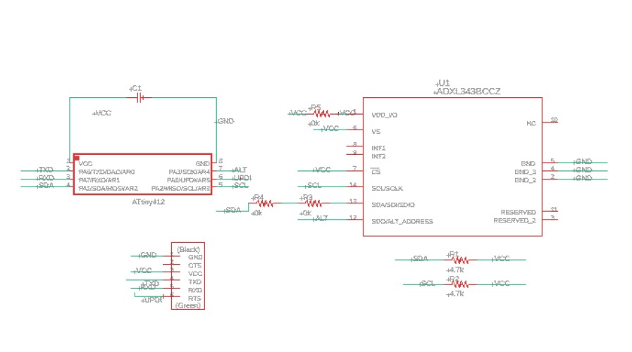
The .sch:
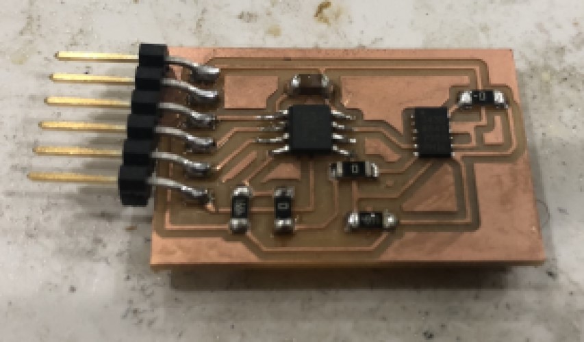
And the board itself:
Programming:
Most of the code I found online used an SPI method instead of I2C, which my board was wired to use. So, I looked at Niel’s example code, and decided to use that instead. However, he used an attiny45 and his connections to the board were different than mine. I thought I vaguely understood how to transfer his code from an attiny45 to an attiny45, but there were a couple of things that confused me. For example:
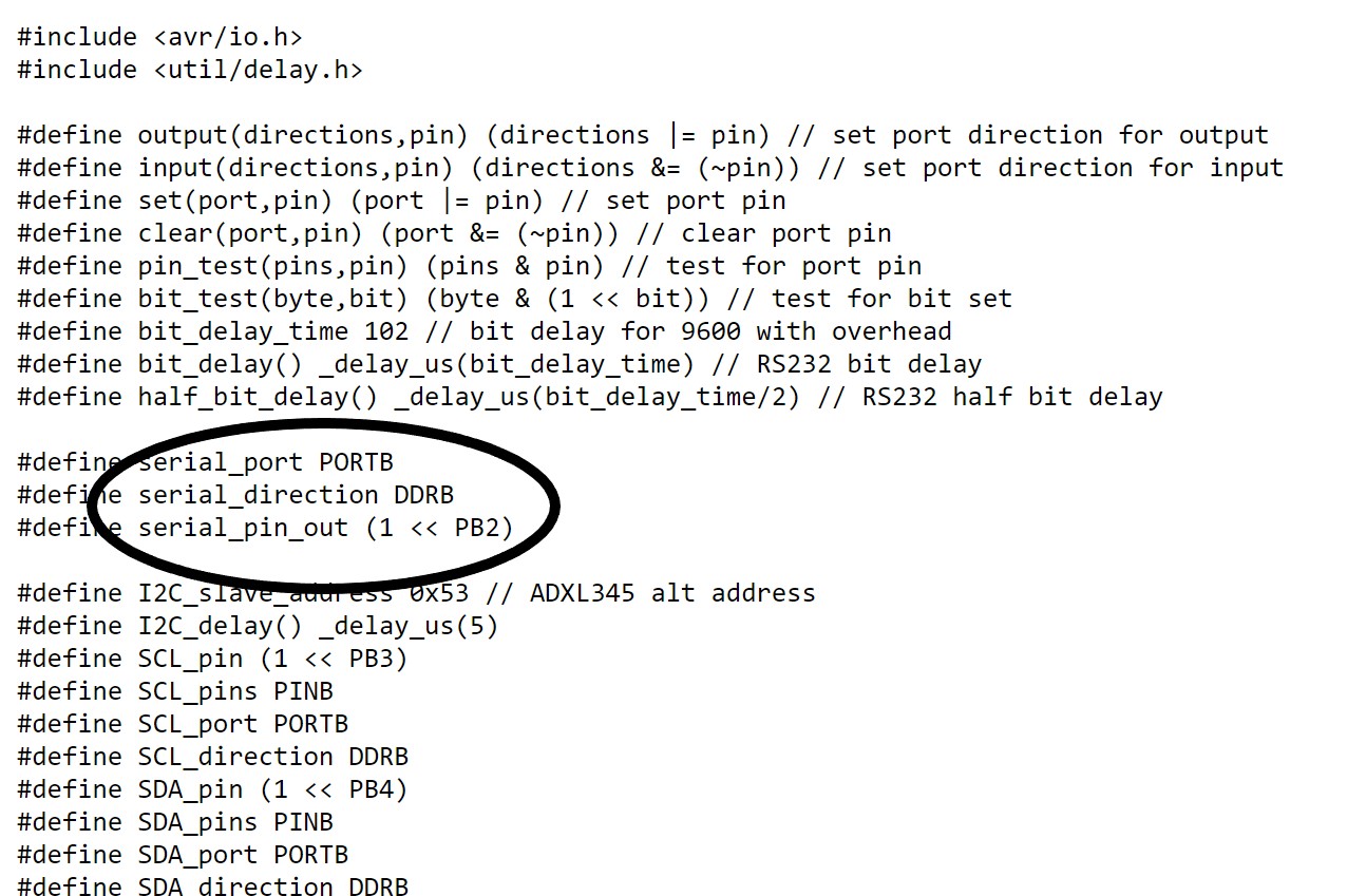
In this part, he defines his serial port as a pin on his attiny45. When looking back at the schematic, I saw that this pin was the RX pin. I rarely actually connect the RX pin. I realized the times that I use the serial port, it is always connected (So, I wrote this location as the RX pin. I also did not understand what “DDRB” meant, according to this site it references the bitmap oriented register that controls the Data Direction of each bit on Port B.” So, I just changed it to “DDRA” because my board uses Port A. I then changed all the other references to Port B and pins on Port B to Port A and pins on Port A. The alt address of the Adxl345 (which he has referenced in his code) is the same alt address as the adxl343, according to the343 datasheet. I am pretty sure the 345 is a breakout version of the 343, so this makes sense.
I ran into a problem when compiling that I had vaguely run into during embedded programming week. Attiny412’s do not seem to use the DDRB syntax, it seems specific to attiny44’s. Originally, I tried using setting the variable equal to “PORTA.DIRSET |= (1 << 7);” to define Pin_PA7 (RX) as an output. It did not work, but I looked back at exactly what DDRx did, and realized that niel simply called DDRx. I saw that later in his functions, he was use functions like “output()” and “input()” that contained the variable calling DDRB and the pin number. I assumed this was the way he set the pinmode as an input or an output, so I should not try to write a byte to PORTA.DIRSET, and instead simply call PORTA.DIR (the “set” part is specific to outputs).
It took me a few tries to figure that out, but with the above method I did not get an error after compiling. Unfortunately, i did get the error that “PORTA” was not declared in the scope of the attiny412.
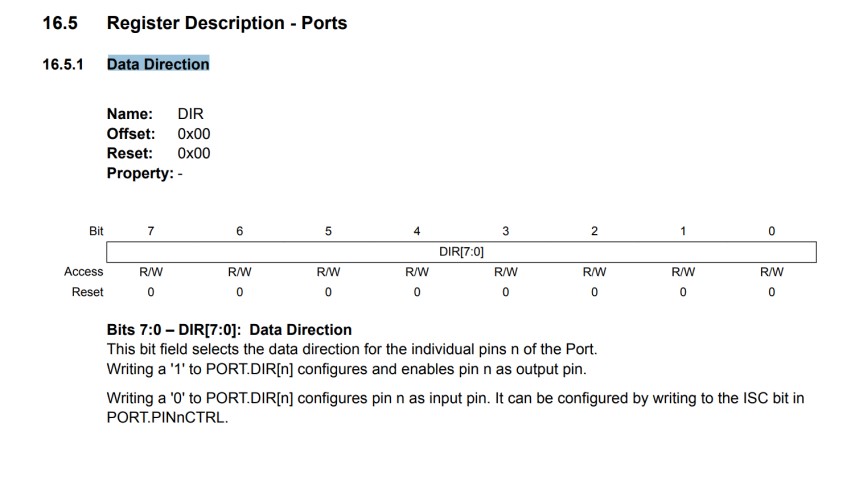
According to the quora I referenced to figure out DDRB, “PORTB is the register your code uses to set the port pins of Port B.” So I started looking over the datasheet for the actual register code for Port A on the attiny412. I could not find it, but I did find this sheet on port multiplexing, with this information about the registers:
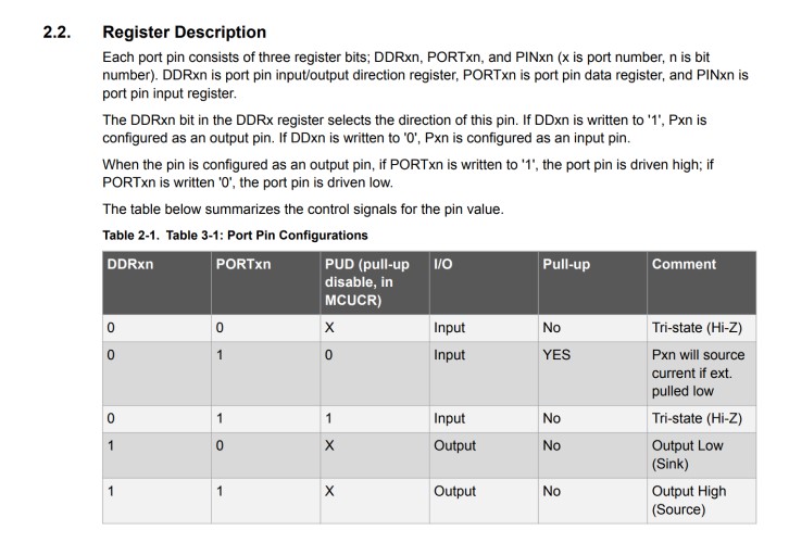
I tried subbing in the information here, but they still were not declared.
At this point I was not entirely sure what to do, so I just tried to write a very simple code for a proof of concept that this board worked. In the future I will need to flesh this code out if I want to use the raw chip in the final project, instead of the MPU-6050, but I will ask my teachers before doing this.
The SDA pin of the adxl343 is the one that actually takes in the data, the SCK is the serial clock. If the SDA pin has any input, a digitalRead(); arduino function of that pin will return “true.” The if statement will print something to serial if the digitalRead(); returns true (is “high”/ the accelerometer moves).
void setup() {
  // put your setup code here, to run once:
  pinMode(PIN_PA1, INPUT);
  Serial. begin(9600);
  Serial.print("serial working");
  Serial.println();

}

void loop() {
  // put your main code here, to run repeatedly:
  boolean variable = digitalRead(PIN_PA1);
  if (variable == true);{
    Serial.print("The accelerometer is moving!");
    Serial.println();
}
  }
It worked!
Video:
Files
stencil.svg (for making the adxl board)