15. Networking and Communications
Group assignment:
Send a message between two projects
Individual assignment:
design, build, and connect wired or wireless node(s) with network or bus addresses
For this week’s assignment I did work for two different systems. One of them is between an accelerometer and motors via I2C, the other is between processing and motors. I struggled a lot with the accelerometer/motor system, so I was still working on it as final project got closer, and I ended up deciding not to use an accelerometer in my final project. I realized at that point that I needed to shift to working on interfacing between motors and bluetooth to get my final project done in time.
So, the first part of my project is the bluetooth and motors work. This part was completed. The second part of my project is the accelerometer and motots work. This part was not completed. It also includes a lot of information that I link to in other pages (for example week 10- input week)
Bluetooth
Learning How to Use Bluetooth Modules
Bluetooth is a communication protocol that exchanges data wirelessly. It operates the same way a serial bus works, by sending and receiving data over TX and RX via a COM port, but wirelessly. I want to be able to send messages between a processing application on my computer and a motor board for my final project via the bluetooth HC-05 module . So, I started by watching this video:
Note: The video is technically about the HC-06 module, not the HC-05, but the differences (for my purposes) were negligible, and I found this video to be very helpful and easy to comprehend.
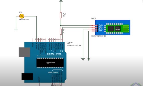
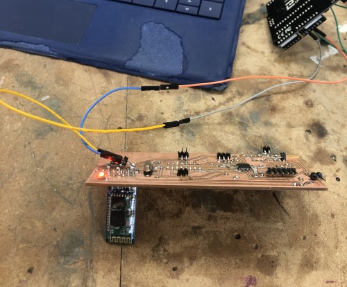
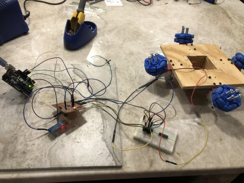
I started by following the tutorial with a breadboard and creating basic communication. The wiring diagram from the video:
My setup:
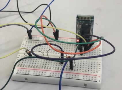
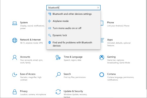
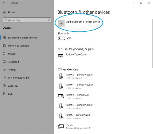
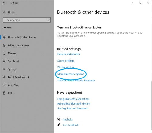
The built in LED of the bluetooth module should be blinking rapidly. This indicates that it is being powered. Next, I paired the bluetooth module to my windows surface computer. The steps to do that are as follows: Go to settings. Navigate to “Bluetooth & Other Devices.”
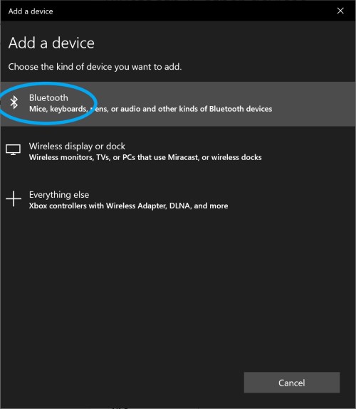
Click add devices and wait for a black screen to pop up. Click “bluetooth.”
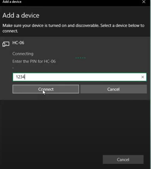
It will buffer for a while. Click on the bluetooth module when it pops up. Enter the default password “1234.”
You need to know what COM port the bluetooth device is associated with. To do this, scroll to the bottom of the page. Select “More Bluetooth Options.” Wait for the pop up menu to appear on screen. Click on the tab that says “COM Ports.” There are 2 COM ports indicated for the HC device. I will use the Outgoing COM port, the one used to transmit data from my computer to the bluetooth chip. The Incoming data COM is for transmitting data from the hardware the bluetooth chip is connected to over to a computer.
I then copied the code from the video tutorial to see if I could initiate contact between the bluetooth module/ arduino and another computer. I uploaded the following code to the arduino and then ran the processing code on the same COM port to see if it worked. with a few simple lines from the video I watched to initiate contact and to print “hello processing”
Processing code:
import processing.serial.*;

Serial sonic_port; //outgoing btSONIC port
String string;

void setup () {
  //open ports
  sonic_port = new Serial(this, "COM11", 9600);
  sonic_port.bufferUntil('\n');
}
void draw() {
  printArray(string); //prints (string) to processing text area
}
void keyPressed() {
  if (key =='1'){sonic_port.write('1');}
    if (key =='0'){sonic_port.write('0');}
}

void serialEvent(Serial sonic_port) {
    string = sonic_port.readStringUntil('\n');}
Arduino Code:
int x;

void setup() {
  Serial.begin(9600);

}

void loop() {
  if(Serial.available()>0){
    x = Serial.read();
  }

  if (x== "1") {
    Serial.println("Hello Processing");
  }

  else if (x == "0") {
    Serial.println("by processing");
  }
}
I was expecting the built in LED of the bluetooth module to start blinking slowly, but it did not. Nothing happened, processing through the error message “com port unavailable” eventually I realized I had the serial monitor for the com port I was using open in arduino, but closing the com port did not fix it. I tried to restart my computer, try other computers, etc, but nothing worked. Fab Alum Mr. Rudolph eventually suggested that something might be running in the background that I could not see, and suggested that I try to force close the COM port.
You can do this in powershell by following the instructions on this site After you type in powershell, type in the following line to create a port variable and assign it to the com port of the bluetooth module. Note- the arduino (attached to the same com port as the bluetooth module) should not be attached to the computer you paired the bluetooth module with. Processing should be running on one computer, the one that is paired to the bluetooth module/arduino, and the module/arduino should be plugged into another computer, where you run powershell.
Line 1:
$port= new-Object System.IO.Ports.SerialPort COM3,9600,None,8,one, hit enter
This should initialize the port variable and attach it to the port “8” that the bluetooth module is attached to. Hit enter
Line 2:
$port.Close()
This should close the port. Hit enter.
Line 3:
$port.open()
Opens the port. Hit enter.
Line 4:
PS> $port.WriteLine(“Hello world”)
Writes “Hello world” to arduino serial port, which is connected to tx and rx of bluetooth, allowing the bluetooth to transmit this to processing.
It does kind of ignore most of the code that tells the arduino to print “Hello world” if key 1 is pressed, so I just deleted that part. With this test, I really only wanted to test if I could initiate contact anyways. After I closed the port with powershell, It worked:

Building the PCB
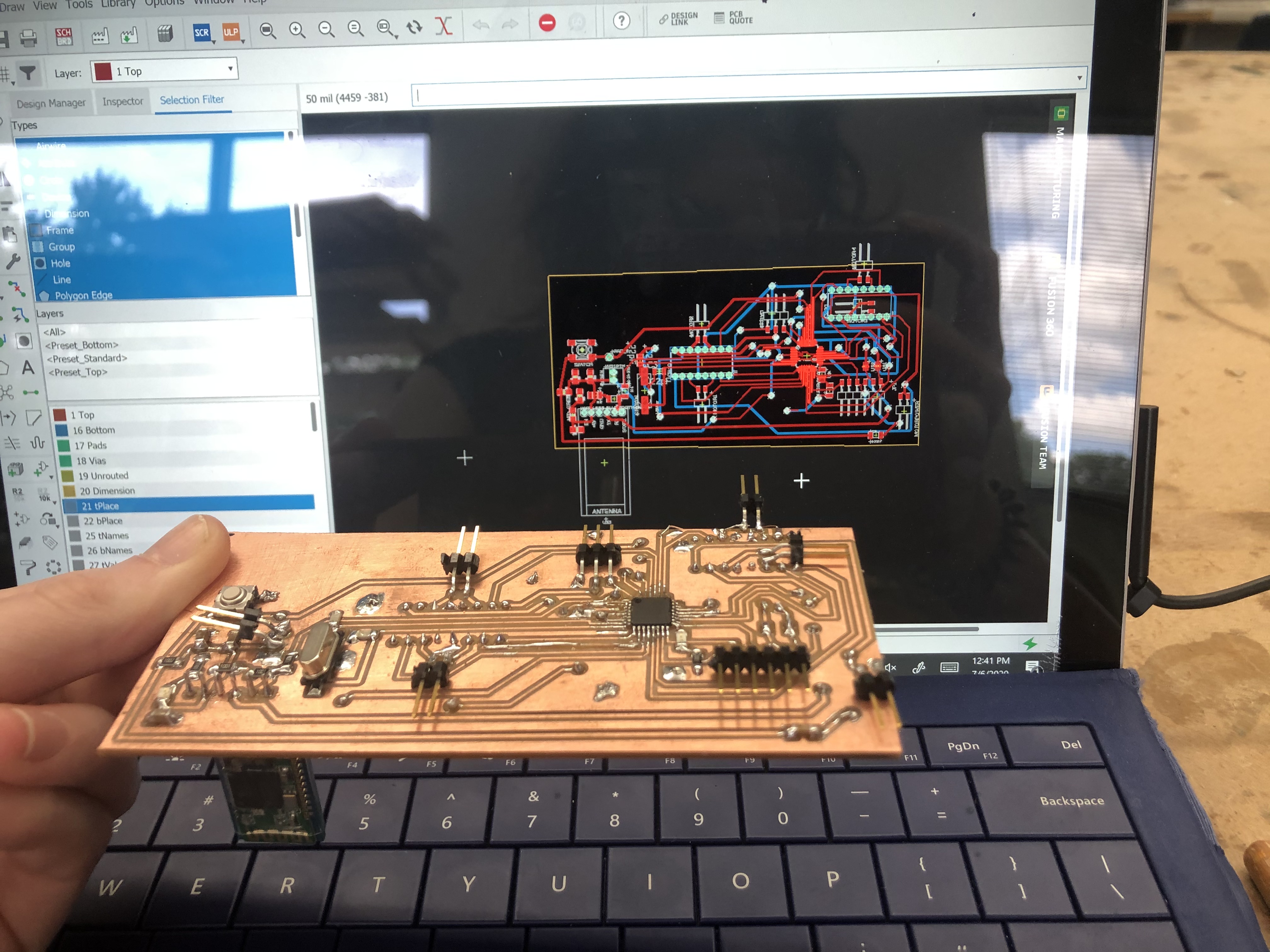
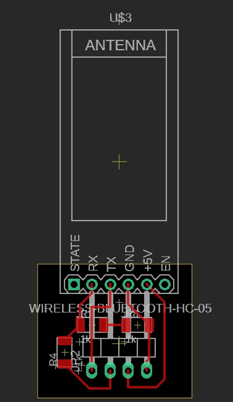
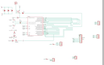
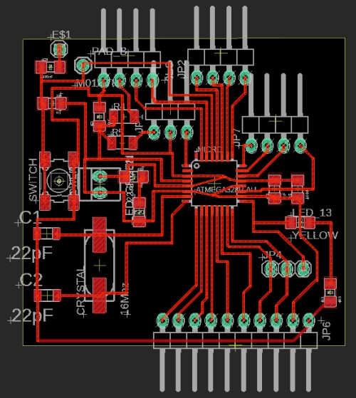
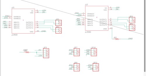
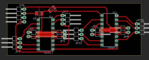
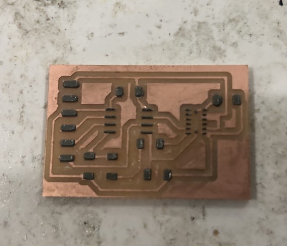
After I was able to initiate contact, I worked on two boards, one was the board connected to a satshakit and also attached to L293d motor chips. Here is a picture of that board and schematic:
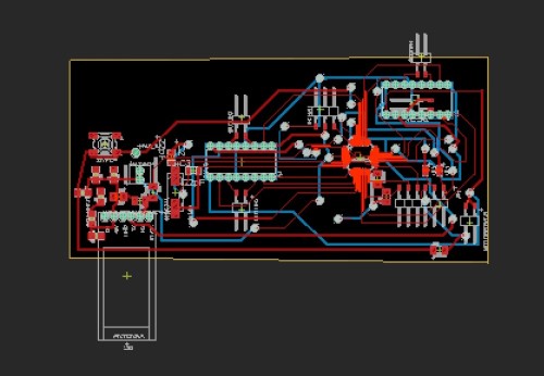
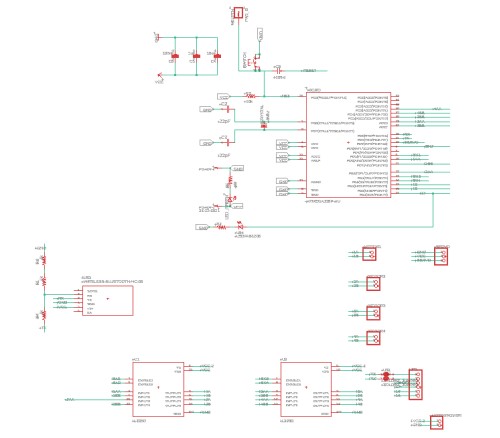
I continually had problems with that board, probably because there were just too many things on one board. One of our fab guru’s Dr. Harris pointed out that I had the capacitors for that board very far from the atmega328p microprocessor, and that might be an issue. Also, I accidentally kept soldering things backwards on that board, and getting things off without ruining the rest of the board. It also would have allowed me to change one board without redoing everything. Also, I shorted this board and burnt the bluetooth chip and the l293d chips. If they were modules and removable, I might not have shroted them, and I would have only had to have redone a smaller fraction of the work. So I decided to make the bluetooth board, the satshakit, and the l293d motor driver board as modules.
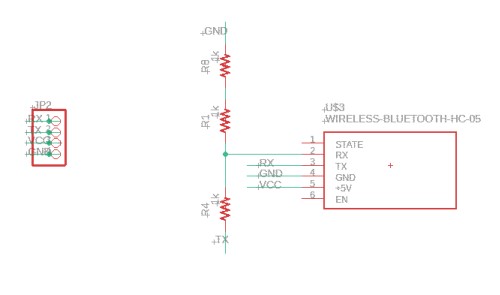
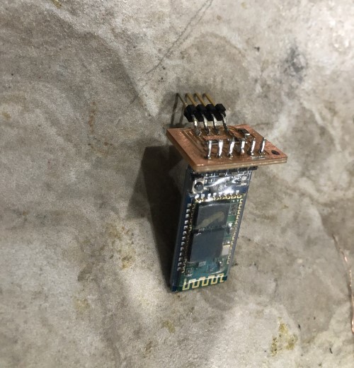
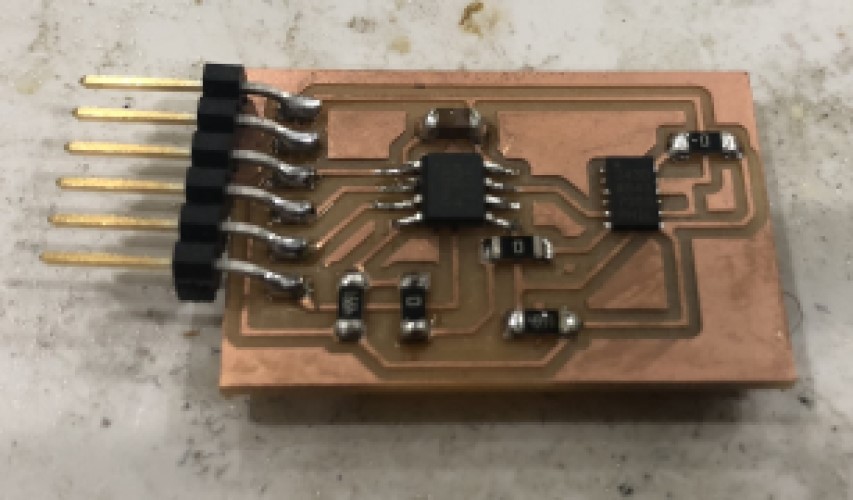
Here is a picture of that bluetooth board as a module:
The satshakit it plugged into:
And the L293D motor driver board plugged into the satshakit:
Note: I downloaded the satshaakit eagle schematic and board file from the satshakit site and added everything I needed to add. The connections I made are detailed more in my final project site.
Motor board module (also plugged into satshakit):
Programming
After I made all the boards, I worked on making a more sophisticated code. What I wanted to do was have processing control the 4 motors of my project. I came up with this as a simple “activation” sketch in processing, that would start the motors of the robot when it ran. Note: again, since I was working on this for my final project, there is a big jump forward in the work that is completed. I did not document the creation of making everything that is in the photos (ie the 3d printed parts, the CNC framework, etc) because it would be irrelevant here. Also, there is some more information about what I did for the code on the final project page as well.
Processing code:
import processing.serial.*;

PImage one;
PImage two;
PImage three;


Serial motor_port; //outgoing btMOTOR port

void setup () {
  //screen:
  size(1020, 1020);
  background(51);
  one = loadImage("CharlotteLatinLogoWhite-01.jpg");
  two= loadImage("Fab_Lab_logo.jpg");
  three= loadImage("cc_icon.jpg");


  //serial
  motor_port = new Serial(this, "COM11", 9600);
 //  motor_port.bufferUntil('\n');

  }

   void draw() {
     background(51);
     textSize(42);
     fill(211,211,211);
     rect(225,  460, 550, 150);
     fill(0, 102, 153);
     text("Sophia Vona", 305, 510);
     fill(255, 255, 255);
     text("Holonomic Droid V1", 305, 550);
     fill(0, 102, 153, 51);
     text("Start in 3...2...1", 305, 590);

     image(one, 600, 0, width/4, height/8);
     image(two, 875, 0, width/8, height/8);
     image(three, 10, 945, width/6, height/16);

  //   image(two, 0, 0);
  //   image(three, 0, 0);


  //  println(hex(byte(mouseX/4)));

    motor_port.write(hex(byte(mouseX/4)));
    println("X=");
    println(2*(mouseX/4)-127);
    motor_port.write(hex(byte(mouseY/4)));
    println("Y=");
    println(2*(mouseY/4)-127);
    delay(20); //needed?

  }
Arduino code:
#define Motor1A  7
#define Motor1B  8
#define en1  6   //motor 1

#define Motor2A  10
#define Motor2B  12
#define en2  5   //motor 2

#define Motor3A  A5
#define Motor3B  A4
#define en3  11   //motor 2

#define Motor4A  A3
#define Motor4B  A2
#define en4  9   //motor 4


void setup() {
  // put your setup code here, to run once:
  Serial.begin(9600);

  //motor 1
  pinMode(Motor1A, OUTPUT);
  pinMode(Motor1B, OUTPUT);
  pinMode(en1, OUTPUT);

  //motor 2
  pinMode(Motor2A, OUTPUT);
  pinMode(Motor2B, OUTPUT);
  pinMode(en2, OUTPUT);

  //motor 3
  pinMode(Motor3A, OUTPUT);
  pinMode(Motor3B, OUTPUT);
  pinMode(en3, OUTPUT);

    //motor 4
  pinMode(Motor4A, OUTPUT);
  pinMode(Motor4B, OUTPUT);
  pinMode(en4, OUTPUT);


  pinMode(LED_BUILTIN, OUTPUT);
}

void loop() {

  digitalWrite(LED_BUILTIN, HIGH);   // turn the LED on (HIGH is the voltage level)
  delay(2000);                       // wait for a second


  if (Serial.available() > 0) { //read bytes when serial has more than two bytes availible
  /*  int X = Serial.read();
    delay(10);
    int X1 = (int) X;
    if (X1 == 1) {

    */
//forwards
      //motor 1
  digitalWrite(Motor1A, LOW);
  digitalWrite(Motor1B,   HIGH);
  analogWrite(en1, 0);


//motor 2
  digitalWrite(Motor2A, LOW);
  digitalWrite(Motor2B,   HIGH);
  analogWrite(en2, 0);

//motor 3
  digitalWrite(Motor3A, HIGH);
  digitalWrite(Motor3B,   LOW);
  analogWrite(en3, 175);


//motor 4
  digitalWrite(Motor4A, HIGH);
  digitalWrite(Motor4B,   LOW);
  analogWrite(en4, 175);

  digitalWrite(LED_BUILTIN, LOW);    // turn the LED off by making the voltage LOW
  delay(2000);

  //////////////////////
  ///back
        //motor 1
  digitalWrite(Motor1A, LOW);
  digitalWrite(Motor1B,   HIGH);
  analogWrite(en1, 0);


//motor 2
  digitalWrite(Motor2A, LOW);
  digitalWrite(Motor2B,   HIGH);
  analogWrite(en2, 0);

//motor 3
  digitalWrite(Motor3A, LOW);
  digitalWrite(Motor3B,   HIGH);
  analogWrite(en3, 175);


//motor 4
  digitalWrite(Motor4A, LOW);
  digitalWrite(Motor4B,   HIGH);
  analogWrite(en4, 175);

  digitalWrite(LED_BUILTIN, LOW);    // turn the LED off by making the voltage LOW
  delay(2000);


///////////////////////////part 2:

//left?

//motor 1
  digitalWrite(Motor1A, HIGH);
  digitalWrite(Motor1B,   LOW);
  analogWrite(en1, 175);


//motor 2
  digitalWrite(Motor2A, LOW);
  digitalWrite(Motor2B,   HIGH);
  analogWrite(en2, 175);

//motor 3
  digitalWrite(Motor3A, LOW);
  digitalWrite(Motor3B,   HIGH);
  analogWrite(en3, 0);


//motor 4
  digitalWrite(Motor4A, LOW);
  digitalWrite(Motor4B,   HIGH);
  analogWrite(en4, 0);

  delay(2000);

  //right

//motor 1
  digitalWrite(Motor1A, LOW);
  digitalWrite(Motor1B,   HIGH);
  analogWrite(en1, 175);


//motor 2
  digitalWrite(Motor2A, HIGH);
  digitalWrite(Motor2B,   LOW);
  analogWrite(en2, 175);

//motor 3
  digitalWrite(Motor3A, LOW);
  digitalWrite(Motor3B,   HIGH);
  analogWrite(en3, 0);


//motor 4
  digitalWrite(Motor4A, LOW);
  digitalWrite(Motor4B,   HIGH);
  analogWrite(en4, 0);

  delay(2000);

    }

  }
Video of the processing controlling the motors of the robot via the bluetooth module:
I2C
The other thing I attempted to do this week I decided to try to connect my input board (accelerometer) to my output board. For my final project, the accelerometer (and other sensor board, like a gyroscope) will take information about the way my self-balancing robot is tilted/facing/moving. This information will be used in tandem with remote controlled inputs to tell the robot which way to move.
I will work on sending information through the i2c bus that is standard for the accelerometer. Attiny’s can also be configured to work through the i2c bus, though it is technically called TWI protocol for them. While these protocols are similar, they do have some differences. However, they are similar enough that they will be able to communicate.
Since I do not yet have all the inputs I need and all the motors, I will simply experiment with setting up the proper I2c channels and making the accelerometer communicate with the motor.
I started by making an accelerometer board. I had designed it in input week, but because I did not have access to the ADXL343 chip recommended by Niel. So, I designed another board that used an MPU-6050. I finally printed out the input board this week.
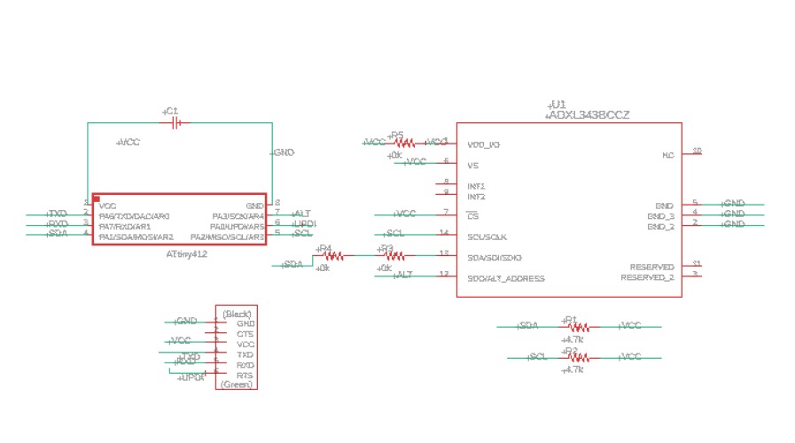
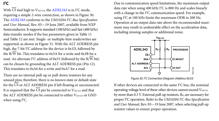
The communication protocol I will use is I2C, which uses only two lines, SDA and SCL, for communication. I2C is one of the main ways the accelerometer is known for communicating. In the datasheet of the ADXL343, there is a section that describes the wiring diagram for I2C communication.
I actually made the board for the ADXL this week. I went back and did input week after I had made the board, but I tried not to repeat any documentation. I made the board on this page, the other page describes programming the device on it’s own.
I’m using an ADXL343 chip on my board. I downloaded the eagle footprint from snapeda.
Soldering this was a bit tricky because I needed to use reflow on the ADXL343 chip. Usually you need to perform a technique called reflow solder that uses a solder mask and a heat gun. This is not normal, but it is necessary for this type of component. I was able to find this sparkfun guide which suggested some other methods, including using solder ovens and skillets. I thought I would have to resort to using a frying pan because I do not have lab access, however, I met with Mr. Rudolph, a fab alumn and one of our node’s instructors, and he was able to get me access to a heat gun. He also taught me the basics of this technique and referred me to a couple of helpful tutorials, such as the video below, which guide me through the process of reflow soldering.
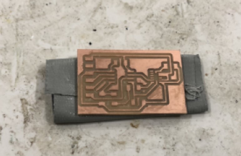
I made a solder stencil, the tool needed so you can easily “brush” solder over your components. This step can be bypassed, but I decided to experinment with it- I do not want to ruin these ADXL chips, and this seemed like a good technique to learn.
Here is an eagle Solder stencil tutorial. You simply have to isolate the “tcream” layer on Eagle and change the fill to solid. I chose to export it as a PDF so I could copy it to inkscape and save it as a .SVG .

My teacher then laser cut it for me (As a student, I do not have lab access, my school/lab does not allow students in it due to the COVID-19 crisis).
I taped the board down, with the stencil over it. I had to be very careful because I wanted to make sure I could get the stencil off without ruining the solder paste that I would put down on it.
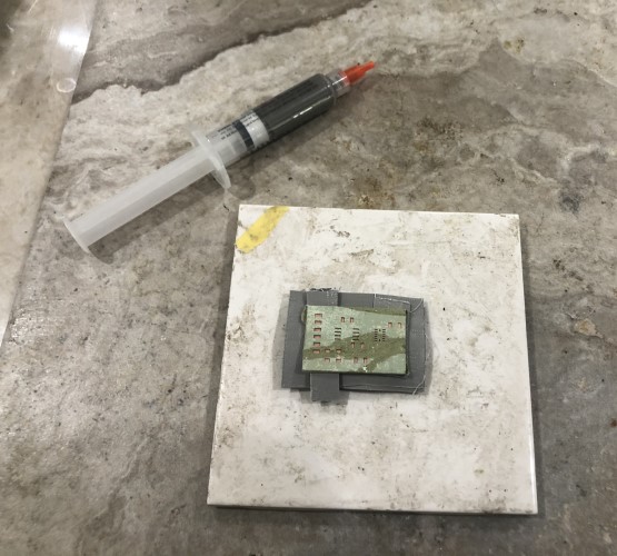
After lining up the stencil, I squeezed a bit of solder paste out of the tube and onto the stencil. I then used a rubber spatula to smear the solder paste over the mask. I went over multiple times to ensure I covered all the edges.
After this, I took off the stencil, and carefully soldered all the components onto the board. Even with the solder mask, soldering the ADXL chip was incredibly nerve-wracking, I thought I was going to drop the chip and smear the solder paste. Thankfully, I did not, and actually got the chip soldered in on the first try. After I soldered every component, I went back with normal solder to reinforce the connections.
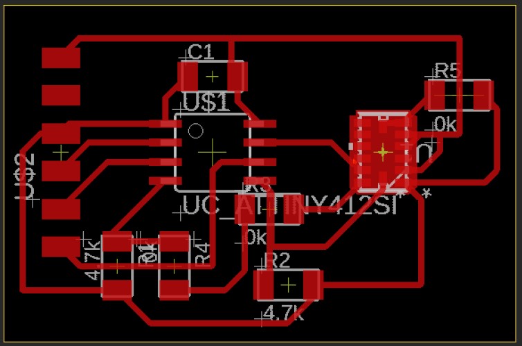
Final board:
Programming
After that, I moved on to programming it.
I was not originally sure how to connect the two boards together. A cursory glance made me believe that I simply needed to connect the SDA and SCL ports of the two devices. I started following this tutorial I found on former Latin Fabacademy students Maxine Tan and Sarah Coston’s fab academy sites. This site confirmed my setup idea, and gave me example code for a Master device that Reads data and a Slave device that writes data.
I decided to use the “MasterWrite” and “SlaveRead” code example instead. I wanted the “Master” ADXL to send data to the Motor. I have read that which device is which does not matter, but this version seemed like a more straight-forward path to get to the same result. I wanted to have the “wire.write()” send data from the ADXL343. This site used a slightly different method, but I stole a few lines of code from there that demonstrated how to read the ADXL343 x position data from it’s register.
The ADXL343 7 bit I2C address is 0x3a.
It also needed the attiny address, to know what to transmit data to. It could not find it in the datasheet, finally I used an example arduino code that does I2c address scanning. I connected the arduino to the device via i2c and the serial monitor returned my device’s i2c adress:
img
#include <Wire.h>

void setup() {
  Wire.begin();

  Serial.begin(9600);
  while (!Serial); // Leonardo: wait for serial monitor
  Serial.println("\nI2C Scanner");
}

void loop() {
  int nDevices = 0;

  Serial.println("Scanning...");

  for (byte address = 1; address < 127; ++address) {
    // The i2c_scanner uses the return value of
    // the Write.endTransmisstion to see if
    // a device did acknowledge to the address.
    Wire.beginTransmission(address);
    byte error = Wire.endTransmission();

    if (error == 0) {
      Serial.print("I2C device found at address 0x");
      if (address < 16) {
        Serial.print("0");
      }
      Serial.print(address, HEX);
      Serial.println("  !");

      ++nDevices;
    } else if (error == 4) {
      Serial.print("Unknown error at address 0x");
      if (address < 16) {
        Serial.print("0");
      }
      Serial.println(address, HEX);
    }
  }
  if (nDevices == 0) {
    Serial.println("No I2C devices found\n");
  } else {
    Serial.println("done\n");
  }
  delay(5000); // Wait 5 seconds for next scan
}
I entered the master slave device address as the ADXL343’s address (0x3A) The register addresses for the ADXL343 is 0x32 and 0x33. I need this because the x data being transmitted is coming from this register, and the device needs to know which register it will find the data it needs in. Here is the code:
// Wire Master Writer
// Originally by Nicholas Zambetti <http://www.zambetti.com> (modified by Sophia Vona)

// Demonstrates use of the Wire library
// Writes data to an I2C/TWI slave device
// Refer to the "Wire Slave Receiver" example for use with this

// Created 29 March 2006

// This example code is in the public domain.

#include <Wire.h>

#define X_Axis_Register_DATAX0 0x32 // Hexadecima address for the DATAX0 internal register.
#define X_Axis_Register_DATAX1 0x33 // Hexadecima address for the DATAX1 internal register.

#define attiny_adress

void setup()
{
  Wire.begin(0x3A); // join i2c bus (address optional for master)
}

byte x = 0;

void loop()
{
  Wire.beginTransmission(attiny_adress); // transmit to motor attiny
  Wire.write(X_Axis_Register_DATAX0);
  Wire.write(X_Axis_Register_DATAX1);
  Wire.endTransmission();    // stop transmitting


  x++;
  delay(500);
}
Finally, I was able to move onto the attiny “slave” device code. I used the same basic layout found on the arduino site where I got the “master” code.
I used all the same addresses described above. I then took my original motor code, and merged these two codes together. I ended up with software that would receive the I2c data (X values), see if the X data was above a certain value. If it was at that value, it would run at 1200 rpm and print “Accelerometer data recieved. Motor running at 1200rpm” to the serial monitor. If it wasn’t receiving x data over that threshold, it would not run and would print “Error. Accelerometer data NOT recieved. Motor not running.” to the serial monitor. This was an arbitrary way to control the motor based on values from the serial monitor.
// Refer to the "Wire Master Writer" example for use with this

// Created 29 March 2006

// This example code is in the public domain.

#include <Servo.h>
#include <Wire.h>             //include libraries
#define attiny_address 0x00   //attiny address variable

Servo ESC;  // create ESC object to control a servo

void setup()
{
  Wire.begin(attiny_address);                // join i2c bus with address #4
  Wire.onReceive(receiveEvent); // register event
  Serial.begin(9600);           // start serial for output
}

void loop()
{
  delay(100);
}

// function that executes whenever data is received from master
// this function is registered as an event, see setup()
void receiveEvent(int howMany)
{
  while(1 < Wire.available()) // loop through all but the last
  {
    int x = Wire.read(); // receive byte as an integer
    Serial.print(x);         // print the character

     if (x > 150) {
        ESC.write(1200);
        Serial.print("Accelerometer data recieved. Motor running at 1200rpm");
      }
      else {
        Serial.print("Error. Accelerometer data NOT recieved. Motor not running.");
      }

      delay(1000);          //waits
      }

    }
I also reviewed this This was a very basic code for one i2c slave and one i2c master using the
#include <Wire.h>

void setup() {
  Wire.begin();

  Serial.begin(9600);
  while (!Serial); // Leonardo: wait for serial monitor
  Serial.println("\nI2C Scanner");
}

void loop() {
  int nDevices = 0;

  Serial.println("Scanning...");

  for (byte address = 1; address < 127; ++address) {
    // The i2c_scanner uses the return value of
    // the Write.endTransmisstion to see if
    // a device did acknowledge to the address.
    Wire.beginTransmission(address);
    byte error = Wire.endTransmission();

    if (error == 0) {
      Serial.print("I2C device found at address 0x");
      if (address < 16) {
        Serial.print("0");
      }
      Serial.print(address, HEX);
      Serial.println("  !");

      ++nDevices;
    } else if (error == 4) {
      Serial.print("Unknown error at address 0x");
      if (address < 16) {
        Serial.print("0");
      }
      Serial.println(address, HEX);
    }
  }
  if (nDevices == 0) {
    Serial.println("No I2C devices found\n");
  } else {
    Serial.println("done\n");
  }
  delay(5000); // Wait 5 seconds for next scan
}
I hope to explore a bit more with bluetooth in the future. Right now I have many things interfacing with the serial moniter. Usually it just prints values, but in my interface and application week I want to send that data to an application, which will then be able to read the signals on
###Files: Bluetooth:
Modular Boards:
Modular Bluetooth Board Schematic
Programming:
Arduino simple activation code
Processing simple activation code
I2C:
I2C Input(Accelerometer) Board Code
###Group Project Link