16. Molding and Casting
This weeks assignment:
Group assignment
Review the safety data sheets for each of your molding and casting materials
Make and compare test casts with each of them
Individual assignment
Design a 3D mould around the stock and tooling that you'll be using, mill it (rough cut + (at least) three-axis finish cut), and use it to cast parts.
Designing
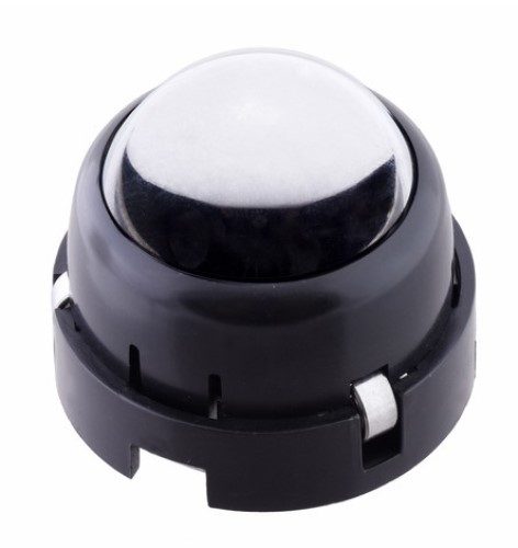
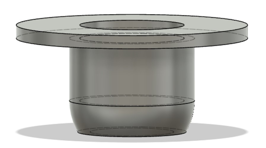
For this week’s assignment, I’d decided to design something I will need to use in the final project. The head of the bb8 droid will be attached to the body by magnets. I need the head to stay up in a stable position, so I want to include small rollers at the bottom of the head, so the head will glide over the body as it moves. I decided I wanted to do this with simple ping pong balls and ball casters, so I will design the ball caster part as something to be molded. I believe I could use resin or a similar material to keep this part light. Here is vaguely what I will want my ball caster to resemble:
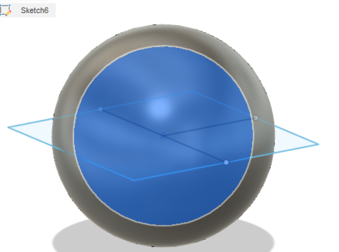
I started just by making two parameters, thick (10mm) and diam(50mm). I used diam to make one ping pong ball. Note, the actual dimensions of a ping pong ball are 40mm, but I want the ball to be able to move around very freely. I am not sure if this is too loose, so I may change this parameter and do some rescaling later.
I then drew another sphere around it with diameter “diam +thick” and drew a box around it using “Diam/2 + thick/2” for the side measures.
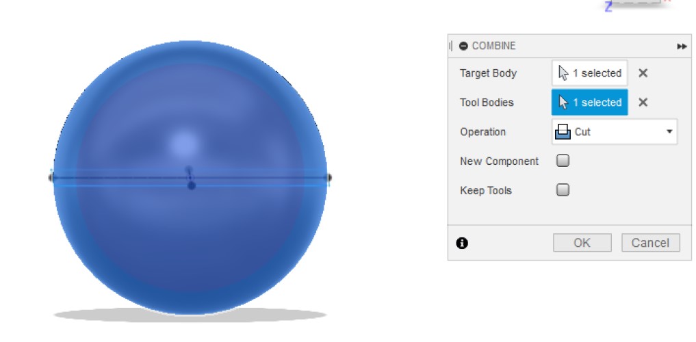
I then used the Modify -> Combine tool and cut out the inside sphere
I then used extrude and removed everything above the top half of the sphere.
I then created a line 15mm below the original square, made sure it was parallel to the original square (by drawing along perpendicular origin planes until I had a line parallel to the plane the original square was on) and I used that line as the axis for Modify -> Split body tool. I made the resulting body invisible.
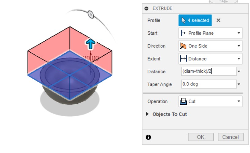
Once I was left with this, I extruded the top portion to “(diam +thick)/2 + (thick/5).”
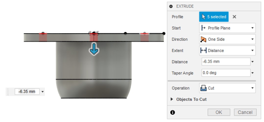
I then extruded an extra 6.35 mm (user parameter qu, = to one quarter inch) and made it a new body. I then used Modify -> Press pull and offset the outside face of the new body by “4*qu” (an inch).
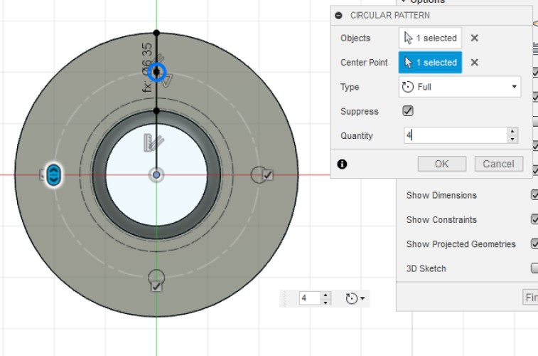
I then made a circle with diameter “qu” at the center line of the face at the top, then used Modify -> Circular pattern to create 4 evenly spaced ones. I then cut out all of these holes with the Modify -> Extrude tool.
I also then extruded the outside of one body as seen in the below photo. The outside cannout curve in, or the milling tool will not be able to pick up those details.

The milling tool also cannot mill overhangs. The plan was to find a way to connect these, then mill them each seperately. However, I am running out of time, so I will simply experinment with manufacturing the part without the overhangs.
Manufacture
Next, I used the Manufacture part of Fusion to create my workspace and toolpaths. In the past I have simply laid out all my pieces so they are flat in fusion, then transferred them to Aspire, where I would create the toolpaths. This week, I used Fusion 360 to make toolpaths. I could not just make toolpaths, however. I also had to create almost a virtual environment of the mill, which included placing the origin, making a virtual tool to mill with, and make/send the toolpaths.
Here were my setiings for the start:
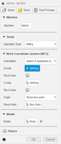
I wasn’t sure what to do with most of the STock because I do not know the dimensions of my foam yet.
Nevermind! I’m making a different mold.
I decided to scrap the original design. I wanted to fit molding and casting into my final project, but I realized I was making this week overly complicated by trying to do so.
Instead of making the ball-caster, I decided to seize on this opportunity and make something fun. I asked a friend for inspiration, and she jokingly proposed a pirate skull. However, I found this good reference photo and decided to use it as a basis for this design:
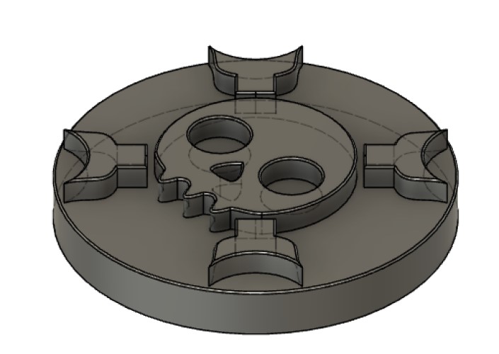
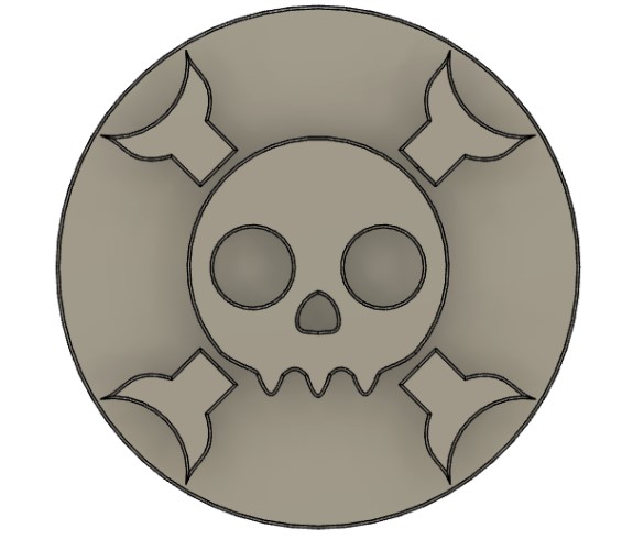
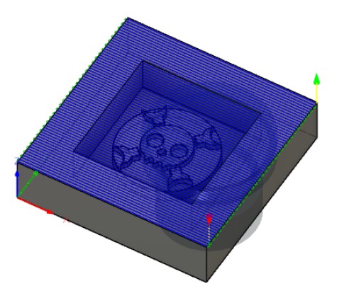
The design only has one side of detail so that it can easily be milled with one mold. The curves was throwing off my sense of measurement, but I used the inspect tool to ensure that the all corners were obtuse, so no dog bones were necessary.
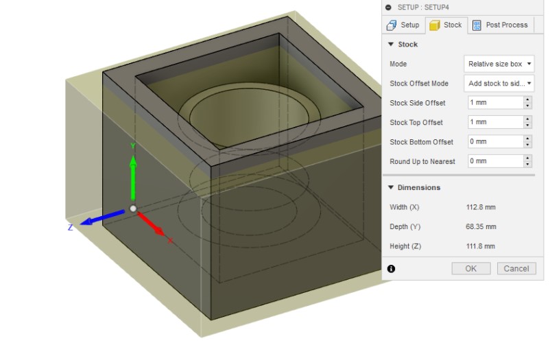
Setup
After creating the design, I started making the toolpaths on fusion. I referenced this video made by fab alumni and node instructor Mr. Rudolph.
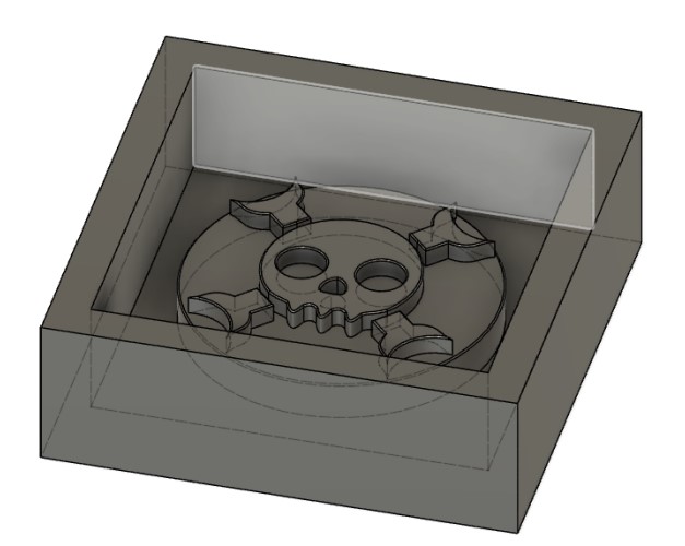
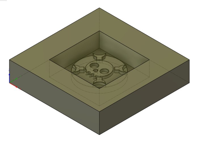
The very first step is to create a hollow box around your object. The walls should all be thick enough so that they do not break, and obviously should be able to support whatever is poured into the mold.
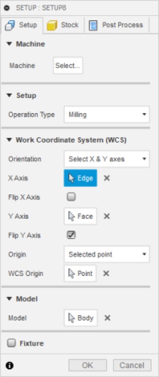
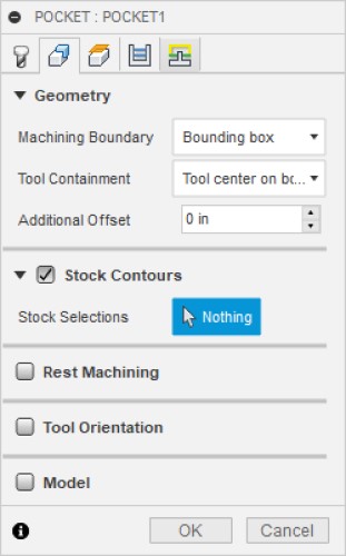
Then, switch to the Manufacture Workspace and select Setup -> New Setup. Select your body.

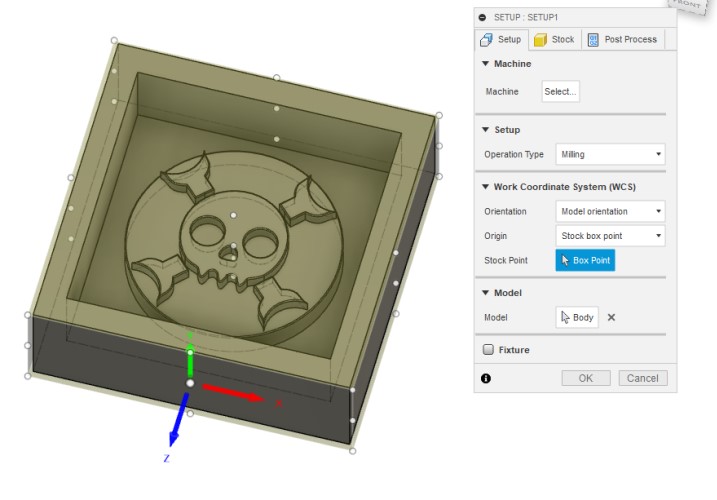
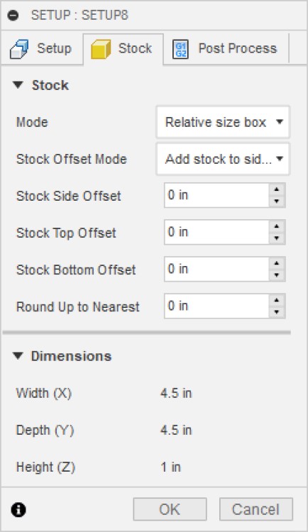
First, we setup the material we are using by changing the settings under the Stock tab. The work for this part actually started when we made the model’s walls. Because the side walls are already an inch and the bottom and top walls were already about the correct dimensions, I set all the Stock Offsets to 0.
Under Setup -> Orientation I manually made the axis match the normal x y and z axis in fusion. Under Setup -> Origin I chose Select Point, and chose to use the bottom left corner.
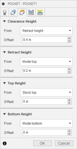
Final Settings:
Creating Toolpaths and a Bit
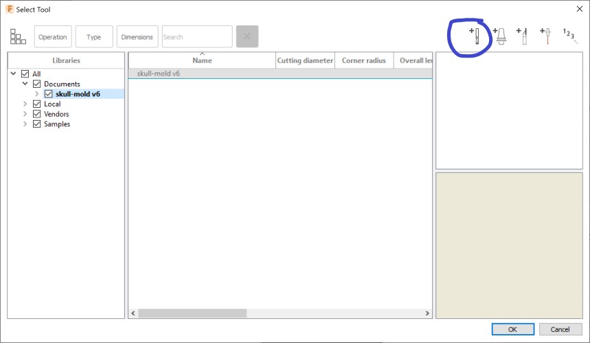
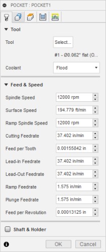
Just as with normal milling, different types of curves/shapes/objects require different types of cuts. However, to make any cuts, Fusion needs to know what tool it is using. Navigate to Manage -> Tool Library and Create a New Tool to do this.
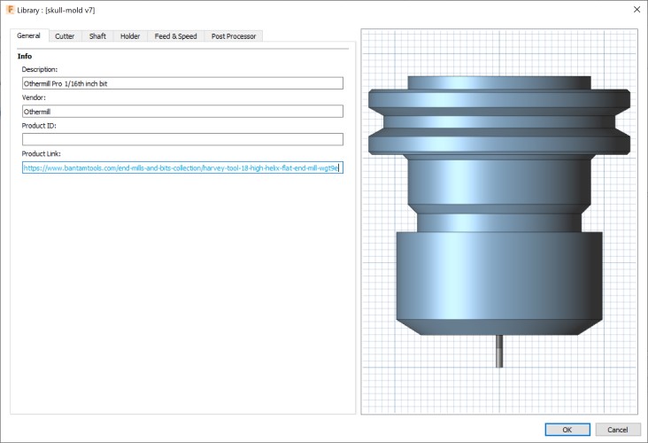
I am going to use an othermill pro with a 1/16th inch bit. The objects I need to mill have some very small details, and I believe my stock/design dimensions can fit in this machine, (upon looking back, I had to edit my design to only have .75 inch offsets, the machine bed is about 4.33 x 4.33 inches, and my original stock was 4.5 x 4.5 inches).
I believe this was the tool we use in the lab, so I referred to these specs.
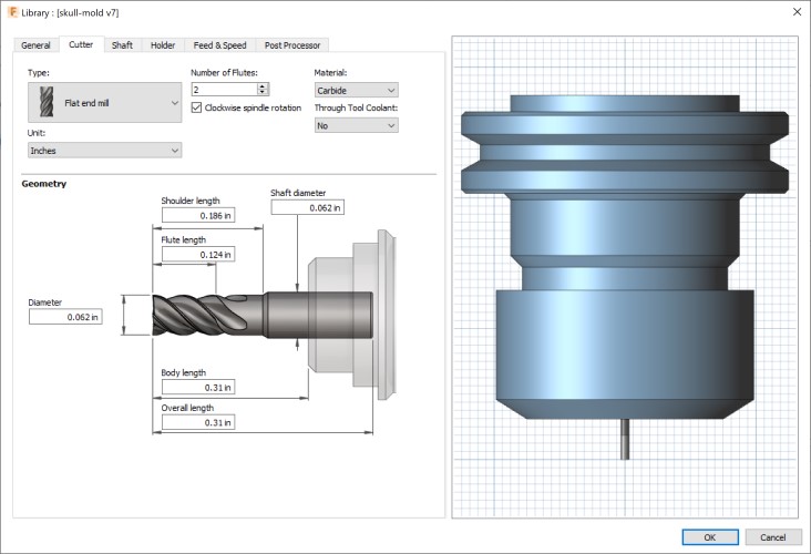
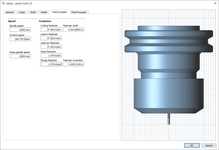
Cutter Diameter: .062” (1/16) Type: Flat end Material: Carbide
I also referenced this site’s information about speeds and feeds. I used the specs from the Machinable wax section, because this site claimed that Machinable foam was most similar to Machinable wax.
Feed rate: 37.402 in/min Plunge rate: 1.575 in/min Spindle Rate: 12,000 RPM Pass depth: 0.014 in
Once I created the tool, I started making cutting paths. The first one I made was a Face cut found under the 2D menu. I did not change any of the settings, I hit ok to create the cut and this image propagated across my design. For now I do not need a face toolpath because I have not set the amount of material that I will need to shave off the top. As soon as I get to the lab I will edit dimensions and change this.
You can even see the bit in the corner.
I also did a 3D -> Pocket Clearing cut:
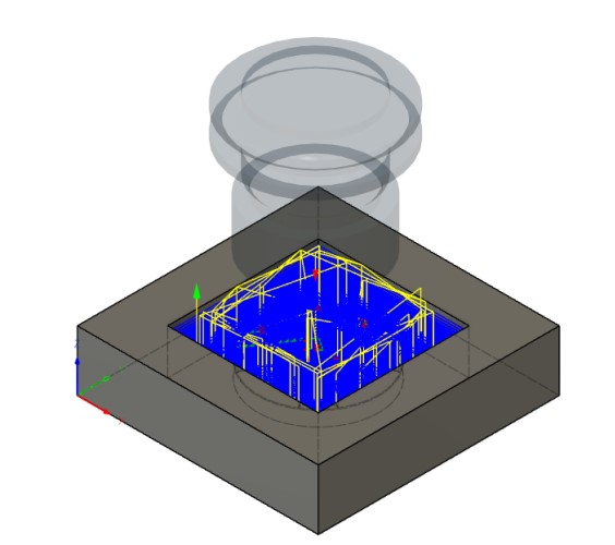
With the following settings
Unfortunately, I ran into the error that “Holder Collides with Stock”
I know for a fact that my collet and holder measurements are wrong (I cannot measure them, I am working from home due to Covid). I am going to continue to create paths, then revisit these issues once I have set the measurements, and address them if they still exist.
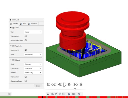
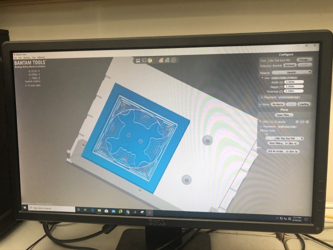
Toolpaths Simulation:
To save the toolpaths as g-code, navigate to Actions -> Post-Process

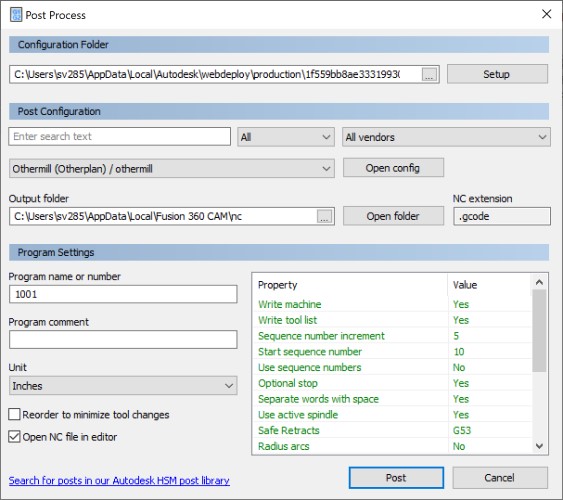
I selected Othermill and set the Document unit to inches.
I saved it, and G-code immediately opened in visual studio code.
Fusion File:
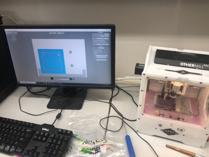
Now I need to upload it to the bantam othermill pro.
Once I got into the lab, I saw the type of material we had available was actually a lot different than what I thought it was. It was actually a wax square with a length and width of 3x3 inches, and a height of .5 inches. Clearly, my original design did not work with this, so I went back and changed the scale of my design so it would be .5 inches tall and would fit within 3x3 inches.
After I did that, I had to regenerate all the toolpaths with the new dimensions. I was still a little worried about the stock colliding with the generic collet and tool I had selected, but I looked at the real measurements of the tool and saw the tool was long enough that the collider could not collide with the stock.
I also changed the tool to a 1/8th tool instead of a1/16th inch tool, so that it would take less time to mill.
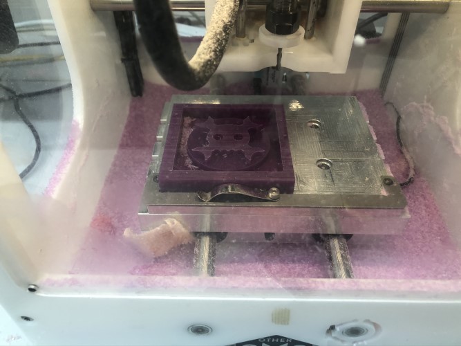
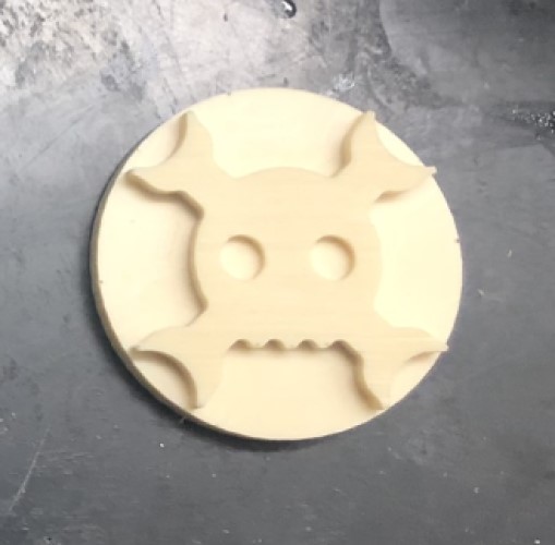
After making these final edits, I loaded the file in bantam tools and milled it out.
This was the final mold. Unfortunately, it didn’t mill the nose, and it did not separate the bones from the outside of the skull. This is probably a result of me shrinking the scale of the body and increasing the tool diameter, but I thought it turned out well.
Molding
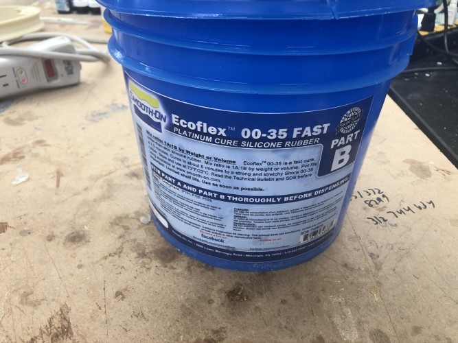
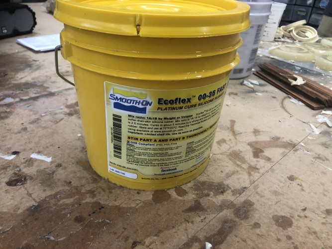
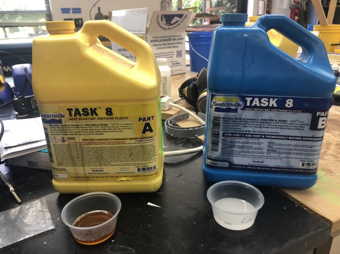
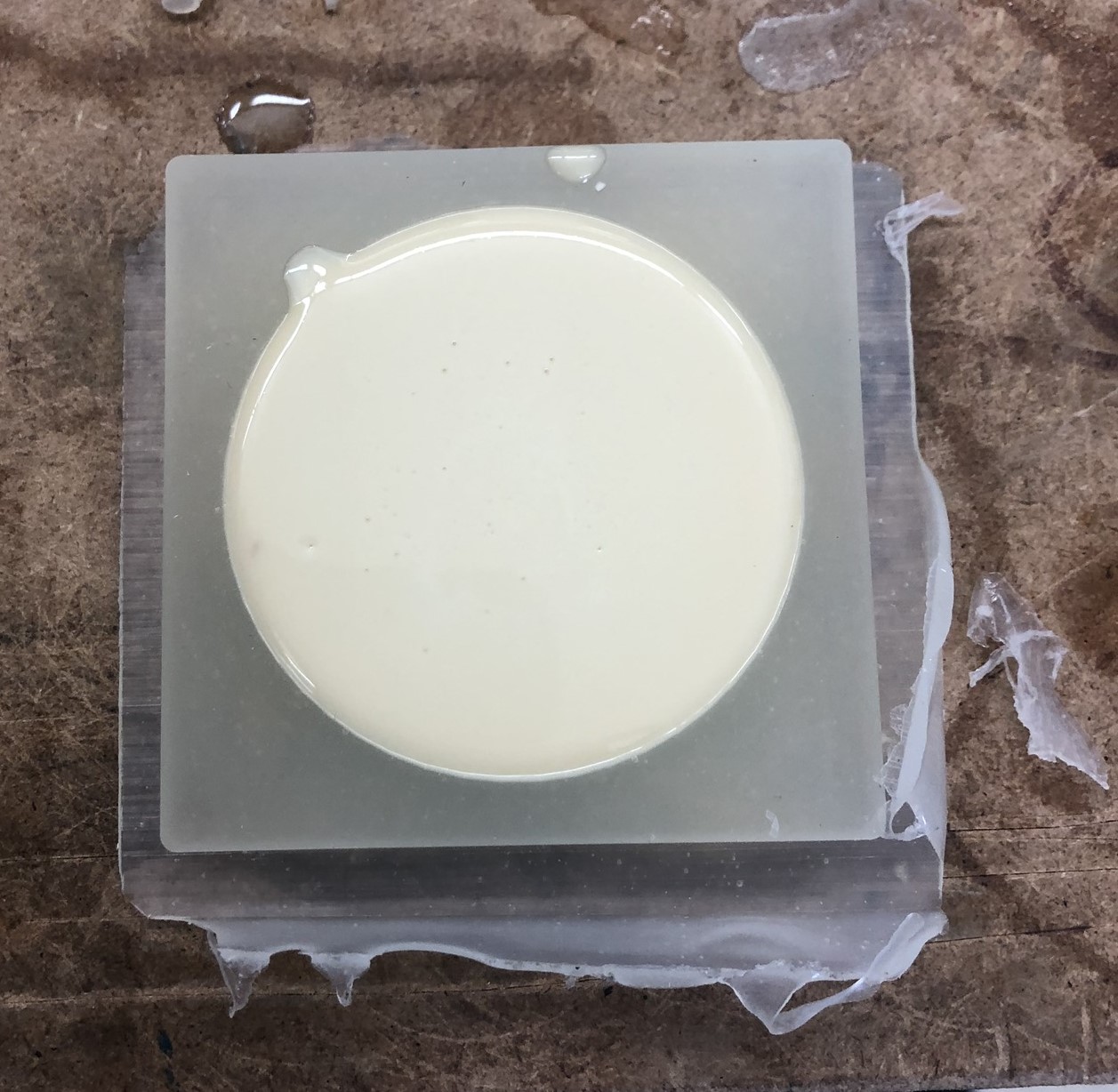
The next step was to make a soft mold out of the wax. I used a silicone material called Ecoflex. It actually comes in two bottles labeled part A and part B. Before handling these materials, I put gloves on, because some mold and cast materials can be harmful (a fellow fab alum has a story about accidentally burning their fingerprints off while using the material task 8. Wearing gloves generally minimizes the risk of losing your fingerprints). I shook both bottles of ecoflex, then poured equal amounts of Part A and Part B into two different cups. I then poured the cup with part B into part A. I stirred the mixture for approximately 60 seconds, then carefully poured it into the wax.
I waited for it to dry, then removed the soft mold from the wax.
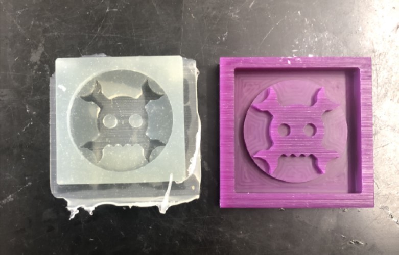
Casting
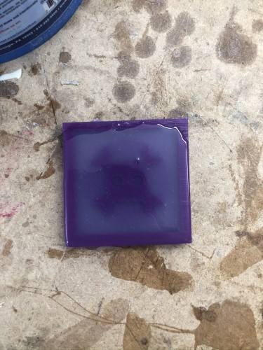
I then used a resin called Task 8 to create the cast.
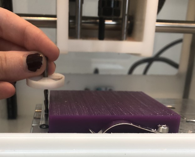
The steps to using this are very similar to with Ecoflex, but I noticed the mold started solidifying at a much faster rate while I was stirring it. It also heated up significantly more than the ecoflex. I had to be a lot more careful when pouring it, because this was the final product. I did spill a little over the side, but it snapped off relatively cleanly and easily.
After it finished cooling, I was left with this final product:
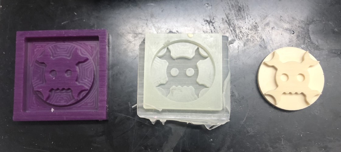
[From left to right: Milled Wax, Soft Mold, Hard Cast (finished product)]