8. Computer controlled machining
Week 8
Individual:
The Individual Assignment this week was to make (design + mill + assemble) a big, original file to be milled with a CNC machine. It must be big enough to explore some of the many facets of CNC, like dogbones, pocket cuts, etc.
Designing
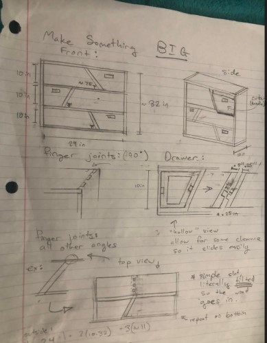
I started by sketching out my design with a lot of details:
I found the design I had sketched out was very helpful. Since I had already thought out all my issues, I was able to simply redraw what I had sketched out. Designing it didn’t take any difficult tools. To learn more about designing in fusion, visit week03 (project 2) on CAD,where I describe it more in detail.
Original Design: I decided to make a mini shelf thing because my grandmother is moving to Charlotte and she likes little storage/display shelves like this.
I found my inspiration scrolling through photos of “CNC furniture,” and found these two sources which I really stuck with for my design. shelf inspiration drawer inspiration
My basic design will be roughly 30” high with a base 24” by 10”. Each shelve will be about 10” and the drawer will take up about ⅓ of the space of the shelf. I tried to outline my dimensions with half inch wood, but this might change so it is a parameter.
Drawing:
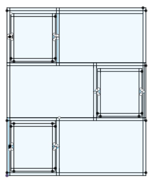
It turned out like this:
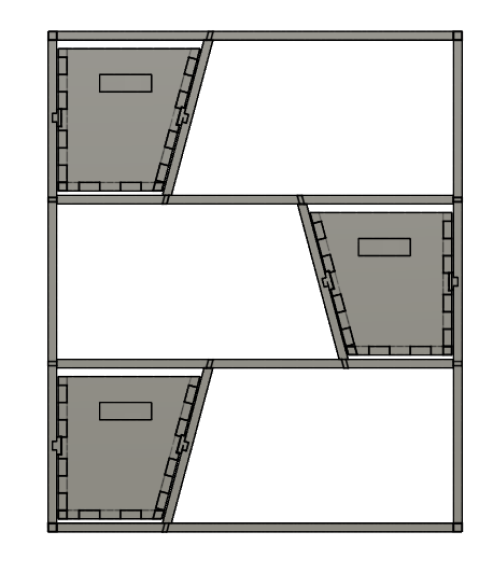
(Front View)
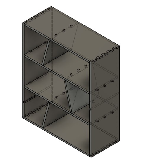
(Outside frame)
My biggest challenge was probably getting everything to fit together. For the most part I was able to simply draw the object I had on my paper and then extrude various bodies, but making every part fit together so it will realistically stay took a while.
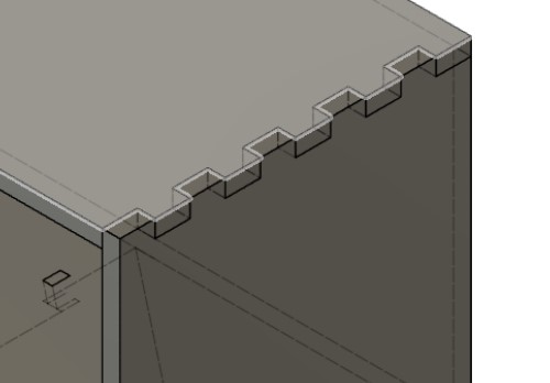
For example, doing the finger joints on the outside took forever just because of how many rectangles I had to draw. I think I drew way too many finger joints, so I will try to lower the number (and make the size of the joint bigger) later to see how those types of finger joins compare.
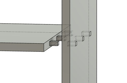
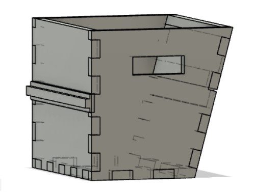
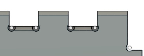
Slide Joints so the “shelves” fit into the frame
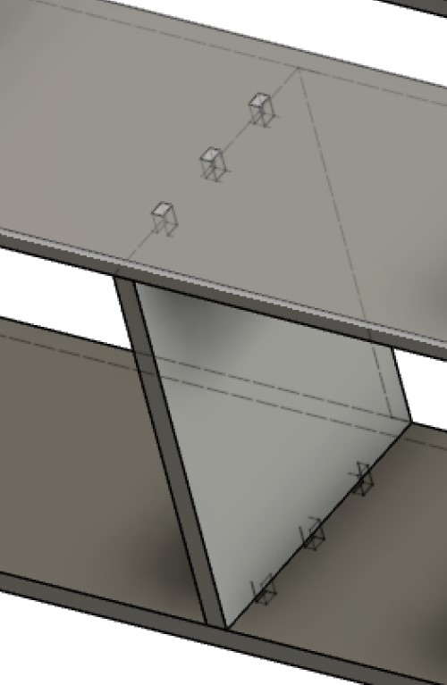
Slot fit angles
This part actually took a minute because I couldn’t just extrude, I ended up having to use the loft tool to get the angle I wanted, which meant I had to draw where both faces would be precisely.
I spent a very long time debating if this would work or not. I think it should hold the component in the overall frame sturdily. I fear the biggest issue will be trying to hold it at the proper angle while putting all the slots together.
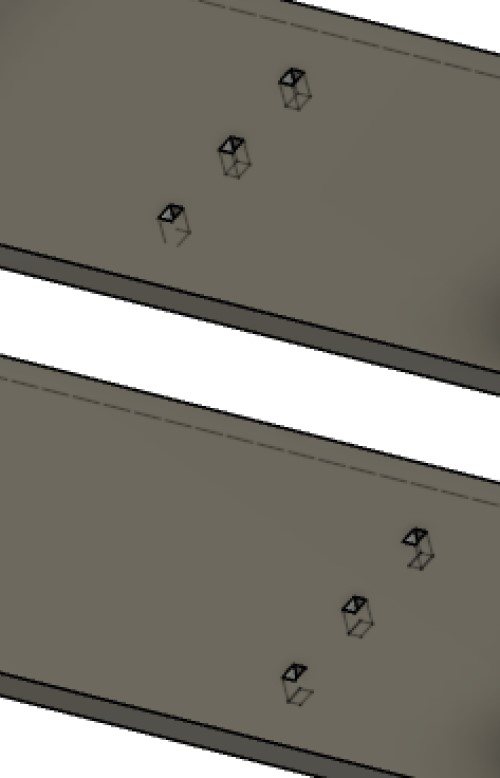
Slot fit angles without the “angled” part (Just the normal part of the shelf that is perpendicular to the frame).
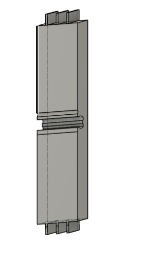
Sliding Shelf component
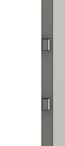
The protruding parts that will allow it to “slide”
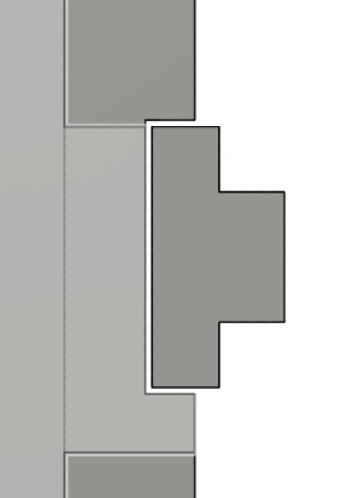
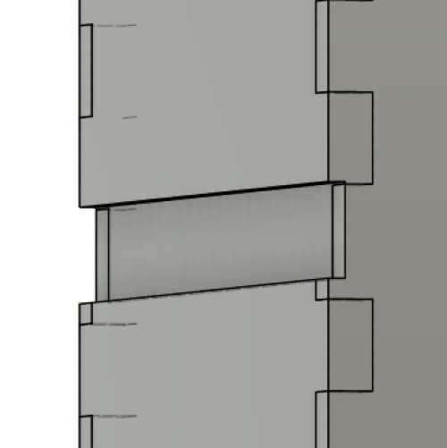
The one difference I made between the sketch on paper (that wasn’t previously outlined) and the finished product was that I used a slot fit on the edges for the shelves in between the top and bottom, which I did not draw. I realized I did not want to use my original idea of just cutting out of the wood in the frame, because I was afraid that would make it unstable and look weird.
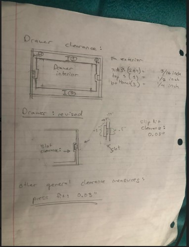
I need this to slide in and out easily, I found the difference in dimensions the drawer should be (compared to the actual object) here.
I also found the clearance for the drawer and the part that it is going to slide on here.
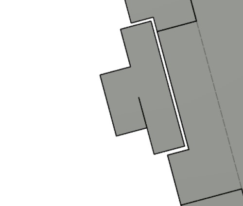
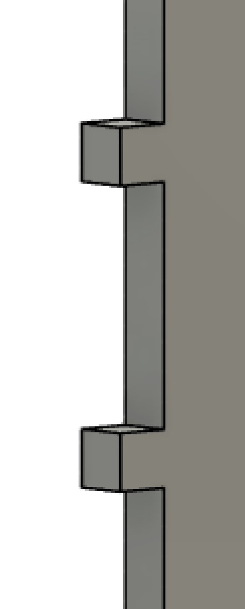
After I had finished and was preparing for cutting, I realized I had made a terrible mistake. My slots are often in the middle of the wood, which our Shopbot can’t cut because it needs to remove wood from under the slots! This was a reallybig error for me. I realized I was having trouble visualizing what the CNC shopbot was able to actually cut.
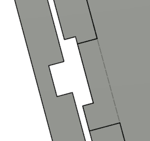
Since, obviously, this design wouldn’t work, so I decided to slightly modify my design by extruding the slot and making it a lot bigger. This actually solved a problem I ran into later when my slots were too small to make dogbones that didn’t intersect (the program wouldn’t make the dogbones correctly if they intersected). I am a little afraid of the stability of the object now, but I think there is still enough material that isn’t cut away by dog bones that it should be fine.
Before:
After:
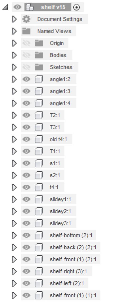
I ended up with way too many bodies, components, and sketches but I wanted to keep them all seperate so I could move them around. This helped make my design process very easy, however, I believe having so many entities in the program slowed it down a bit, which is something to note about this tactic
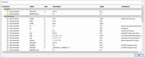
My parameters:
Preparing for cutting:
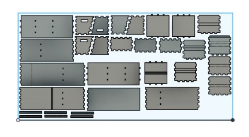
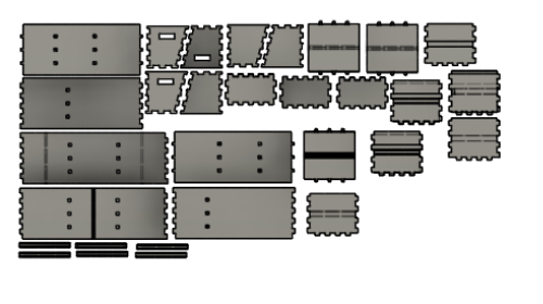
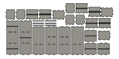
As of now, our school (and the school’s Fablab) has been shut down because of Corona, so I won’t be able to print my design until later. To prepare it, however, I seperated all the components and lined them up on a 4 by 8 foot rectangle.
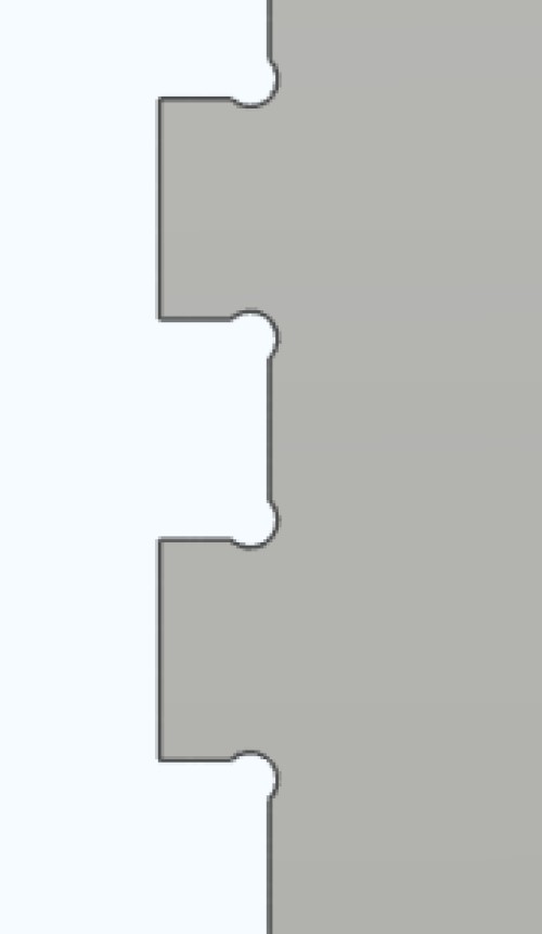
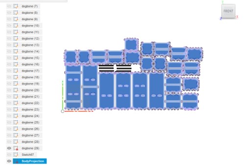
I also used a dogbone plug-in on fusion for all the 90 degree angles. The tool on a CNC machine is round, and cannot fit into the sharp angle. Most of the time the resulting curve the tool will make (without dogbones) will not work for slot fit. To make sure it can, we create rounded edges around the angle so the CNC bot creates the necessary curve in a place we can control, instead of in the place the machine forces itself to go.
I had so many dog bones to do! So I used a plug-in I had stumbled upon a while ago for a different project found herehere, downloaded it as a self extracting file, then had to go to Solid -> Create. At the very bottom of that dropdown menu is the Dogbone tool.
The tool menu looks like this:
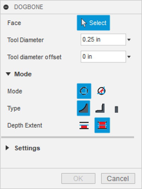
Settings: Tool Diameter: ¼ Normal Dogbones(first option) Static Dogbones(parametric will sometimes put dogbones on some faces but not others, but Static worked much more consistently and I couldn’t find any major differences with how they looked. I don’t think I will need to do any scaling at this point (which I believe the parametric mode is for) so it shouldn’t be an issue.
Flat objects worked very well. I only needed to select the front-face, and the tool would select the and the dogbones were selected in the appropriate places I wanted them to be.
However, I realized the tool had some issues with the angled pieces I made, as well as the smaller slot fits I had made. The slot fit issue resolved itself when I realized my slots didn’t work, and I made them all a lot bigger.
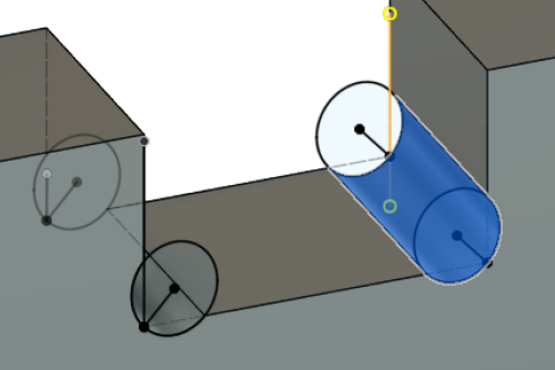
The Angled pieces were a bit more tricky, because it constantly tried to make the dogbones perpendicular to the original face, and wouldn’t let it tilt.
In these cases, I ended up drawing where the dogbone should start and where it should end, then used the loft tool to cut through these two faces.
There were also “pocket” cuts for where the drawer will slide in and out. I had to be very careful to include dogbones on all the bodies where these pocket cuts occured.
Final:
(make sure to view the front of it)
I had hoped to make a prototype of this design by moving all the objects to corel draw and lzser cutting them out at a much smaller scale. I do not know how I would have made the pocket cuts, but I would have at least gotten a general idea for if most of my design worked. My plan for milling would be to then export my fusion file as a .dxf to a program called Aspire which makes toolpaths and prepares for CNC milling. In the group project we experimented with this program, and I found this interface to work very well and have a very straightforward design. Unfortunately, our lab closed on very short notice because of the Corona Virus, and I lost access to the lab. When the Lab reopens, I will finish preparing my files and cut my file. To see the work done with preparing other files and cutting them, refer to the group project site.
I came back to the fab lab to print my design (many weeks later, post COVID mandatory quarantine). Unfortunately, I think the rush I was under to try to get the design done/ my relative inexperience with CNC that week had made me make a lot of mistakes. I started to look through and make a list of everything I had to fix, but there was so much that I designed it was easier to just resketch and redesign the piece of furniture. I tried to edit my original sketch and make changes, but I did not make my design very parametric (lesson learned, my designs should always be parametric), and I soon realized it would be easier to simply resketch it.
Firstly, the shelf has bent parts, but the shapes I made cannot be milled without double sided milling. This is not something I have access to, so I am going to simplify my design and simply make the parts flat.
Secondly, many of my slot fit parts have weird dimensions. Some account for kerf, some do not, and some parts that should be mirrored from one side to another are not mirrored. This was a big error I made that I lost a lot of time trying to fix.
Here is my design with these errors fixed. It is completely parametric.
My new parameters came from these sources:
New fustion file:
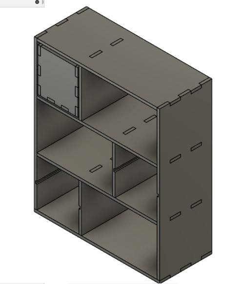
(copied shelving components, which are identical, 3 times to save time)
Aspire/Creating the CAM Toolpaths
First I had to export my work from fusion.
To do this, I then lined up all the bodies so they were on the same plane, pocket cuts facing up. I selected all the faces, then created a new sketch and selected “project.” This projected the faces into one sketch. I then exported just that sketch (by right clicking and selecting export as .DXF)
I then opened the dxf file in Corel. I used corel to clean up the dxf/ prepare it to be made into a CAM path for the CNC machine.
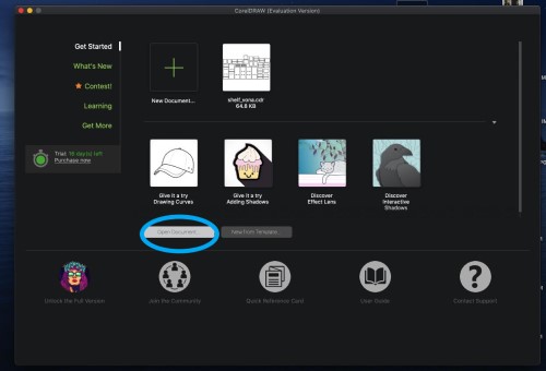
Side note: I usually I do work on a Windows cpomputer, but the following work was done on a mac I borrowed from my mom because my 16 day free trial of corel had ran out on my computer. I sent the .dxf file and downloaded another free trial to my mom’s computer. The steps are almost identical.
Once you open corel, open the dxf file by hitting the “open file” button on the main page.
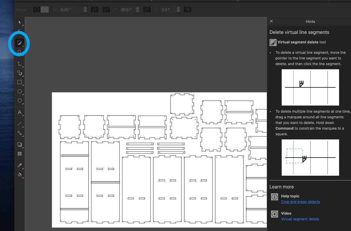
When the file opens, I went to the virtual segment deleter. If you click the icon in the circle, then click the tiny triange on the bottom right corner of the circle, multiple icons will pop up. One has the image that is currently pictured in the circle, click on that and the virtual segment deleter will be selected.
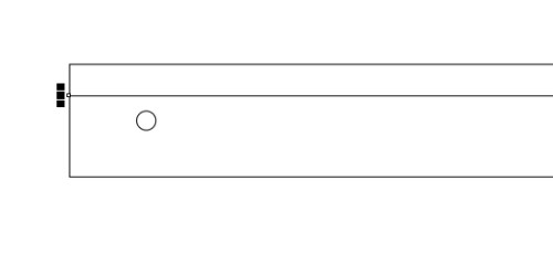
I deleted any extranneous lines I did not want being milled. For example:
Before:
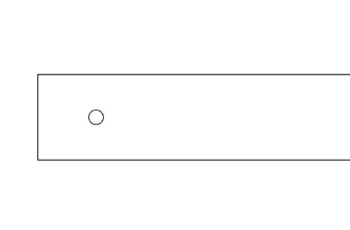
After:
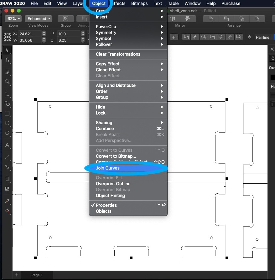
Then, I went through and highlighted each of the shapes one by one to I could “Join segments.” This is necessary because sometimes lines in a closed shape look closed to the nakes eye, but are not truly connected. This will be a problem when I try to use Aspire to create a CAM path, because CNC machines can only mill closed shapes.
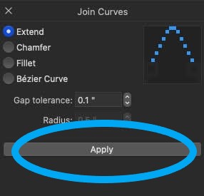
After selecting the shape, navigate to “object -> join curves.” A menu will pop up on the side I hit “apply.” I was not interested in changing any of the settings. If for some reason, the segments were not being joined, I could try upping the gap tolerance. This means the join curves function would join things that are a little further apart than what the initial tolerance allowed for. However, I did not experience this issue. An easy way to test if the segments join together is by deselecting the shape, making sure only one segment is connected, and trying to move it. If the entire shape moves, the segments have been joined into one shape. If only the selected segment moves, you need to up the gap tolerances.
When I was finished, I quickly opened this corel file on the computer connected to the laser cutter and cut it out there. I scaled the file down and cut it out on .5 cm plywood. I was a little concenered because the tolerances seemed very loose, so I consulted with my teacher and fab alumni Mr. Rudolph. He suggested that they were probably only too loose because I was trying to scale down the file, and that the tolerances I had selected seemed fine for the type of shelf I am making. So, I exported the file into Vectric Aspire to create the CAM toopaths.

Aspire
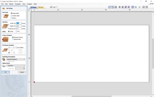
Once you open up aspire, you hit “File -> Open ” and then I loaded my file.
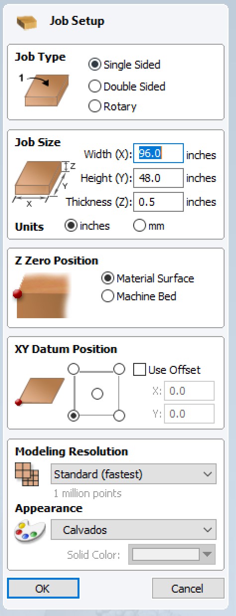
Once you open the file you see this menu, which sets up information for milling. I selected single-sided milling, set the length and width of the CNC machine, set my wood thickness to .5, and left the rest alone.
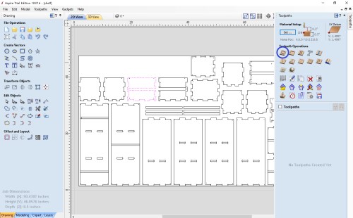
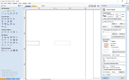
To make the actual toolpaths, click the toolpath bar in the right corner. As you click on each shape, it should appear pink. In the toolpath bar, you can select the type of tool path you need. The outside cuts need a “pocket cut,” selected in blue.
I set the pocket toolpath settings to what follows:
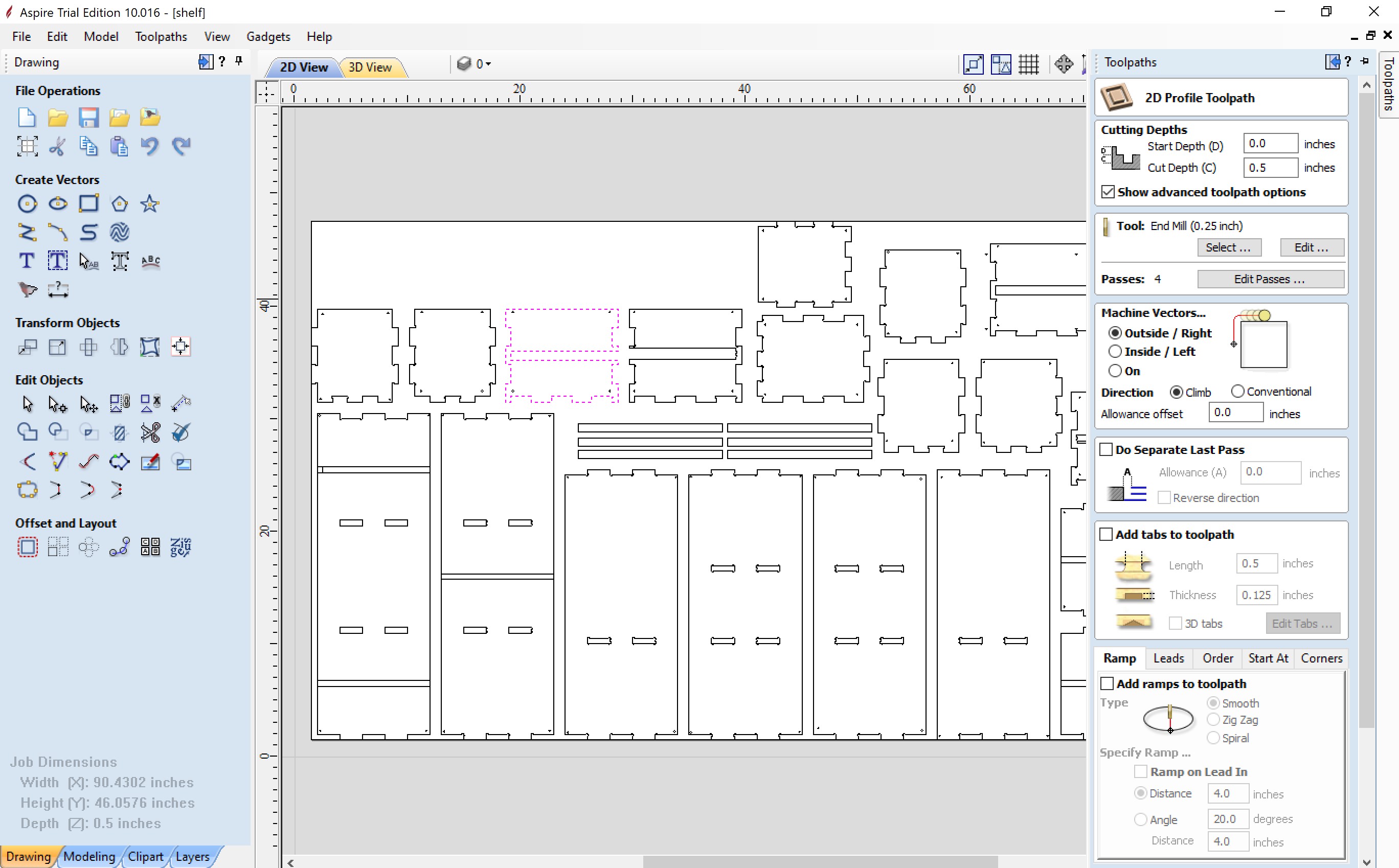
I had to make sure the machine vector was set to “outside/right” of the path. This way, the tool cuts on the outside of the vectors, otherwise it will cut the shapes smaller than they are supposed to be. The thickness of the wood is set to .5, so it cuts all the way through. Then I scrolled all the way down, named the toolpath, and pressed save.
The next toolpath needed is the pocket cut (one to the left of the profile toolpath), for all the dogbones. This one, by default, cuts on the inside. It also cuts all the way through the wood.
The last toolpath was the screw toolpath. I created holes in all 4 corners of each piece of wood, and used a “screw hole” toolpath, the third image away from the profile toolpath.
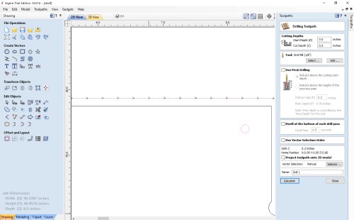
This type of toolpath uses a drill toolpath, and this screen popped up.
I selected this 1/8th inch tool, and made a couple of changes after measuring the actual 1/8th tool bit in the lab. Then I calculated the toolpath.
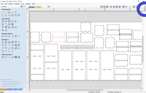
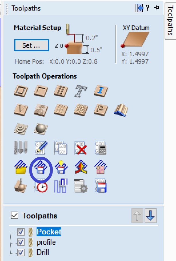
After going through and selecting all the profile, pocket, and drill vectors manually, I recalculated the toolpaths so there was only one toolpath for each type of cut. Then, I exported the toolpaths separately by pressing the button circled below, on the mainscreen of the toolpath sidebar.
I sent these aspire toolpaths to the computer associated with the lab’s CNC Shopbot, and opened them in the Shopbot application on that computer.
Milling
The next step is to actually use the CNC machine! I used the Alpha Shopbot[https://www.shopbottools.com/products/alpha] in our lab, and used the school’s workflow provided by our fab guru teachers, as seen below:
Shopbot Cutting using Aspire/ VCarve Toolpath


Shopbot Machine
Put on eye and ear protection
Close the doors
Check to see that the machine has been warmed up
Check to see bit is not loose
Measure the thickness of material that you plan to cut.
Calibrate Z AXIS on the table.  (C2 keyboard command)
Raise Z AXIS 6 inches using the JZ 6  command
Attach material to the table using screws
Raise Z AXIS 6 inches using the JZ 6  command
Use the proximity switch to set Calibrate.  (C3 keyboard command)
Set new X and Y Origins for your design
Raise the Z-axis so the bit won’t drag on the table
Using keyboard jog to the appropriate X and Y location. (J2 X,Y)
Using keyboard to zero the appropriate X and Y Location. (Z2)
You set origin.
Select Cut
Start up Aspire and VCarve software
Open your file
Select objects you wish to cut
Select Toolpath
Pin Toolpath
Click on material setup
Check Z - zero is on the bed, NOT the board
Enter the thickness of the material *
Model position material should be the same thickness as the material.
Click OK.
Go to TOOL PATH OPERATIONS
Select 2D Profile Toolpath
Under cutting depth, select the cut depth of the material (CLS tools).
Select the proper tool -CLS down bit ¼
Click add tabs and add tabs
Hit CALCULATE.
Preview toolpath
Click on CLOSE
Select SAVE TOOL PATH and save the file in a shopbot format

Start ShopBot Command Console
Conduct air cut
Select FILE-LOAD
Load the appropriate file
We Select 1 3-D offset
Press ENTER
Turn on the spindle by pressing the big GREEN Button
You should hear a  “SOUND” of the spindle now turning
Press ok
After checking that everything is good; press space bar
Select quit
Return to origin (J2 0,0)
Perform cut
Select FILE-LOAD
Load the appropriate file
Select no offset rather than 1 3-D offset
Press enter
Turn on the spindle by pressing the GREEN Button
You should hear a  “SOUND”
Turn on the vacuum
Press enter again to start cut
Cut is done
Turn off vacuum (which is so loud you shouldn’t forget)
Clean up after yourself
I calibrated the Z axis by placing a 1 inch block under the bit, typing the “C2” command into the console,and hitting enter. I then raised the Z axis 6 inches by typing “JZ6” into the console.
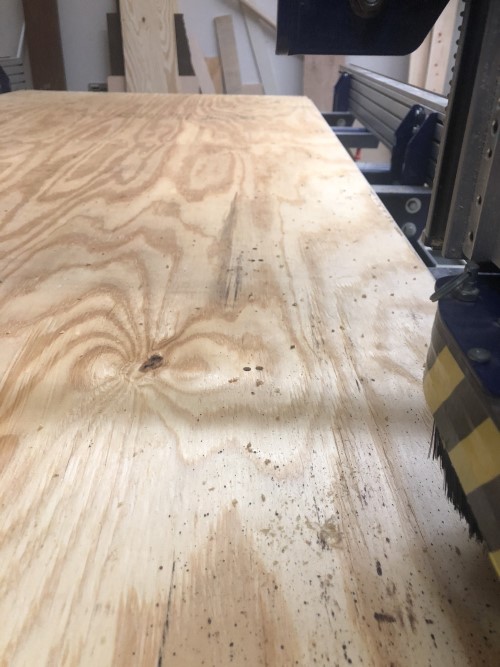
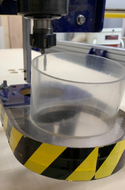
I then put a sheet of .5 inch wood over the machine, and secured it using 4 screws. Here is a picture of the sheet of wood I am using.
So, the first path I had to mill is my “drill” toolpath. This is because my design takes up most of the woodsapce, so the wood would not be a very good framework on it’s own. As seen in my design, there are 4 screws in the corners of all the pieces I am milling. So, I screwed in a 1/8th bit.
Picture of the collet:
I used the C3 command to calibrate the X and Y axis. I moved X and Y over one inch (J2, 1, 1) so the bit would be right over the edge of the wood. Then I used (Z2) to set this position as point (0,0) or home for the X and Y axis.
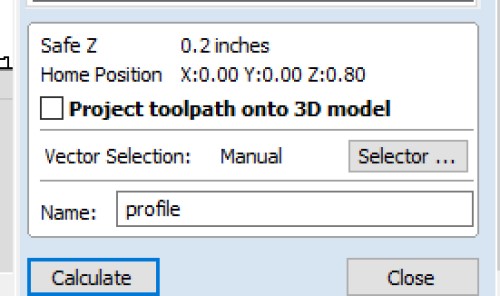
I then opened the drill toolpath sbp which I exported from the aspire file. A menu popped up (yellow notepad block in image) and I left all the settings alone except the “Offset in 2D or 3d?” setting, I chose 3d offset so the toolpath would run an “aircut” a few inches over the wood. This allows me to confirm that the machine is doing what I expected before actually making any cuts. After this, I changed the offset to 2D, and ran the file.
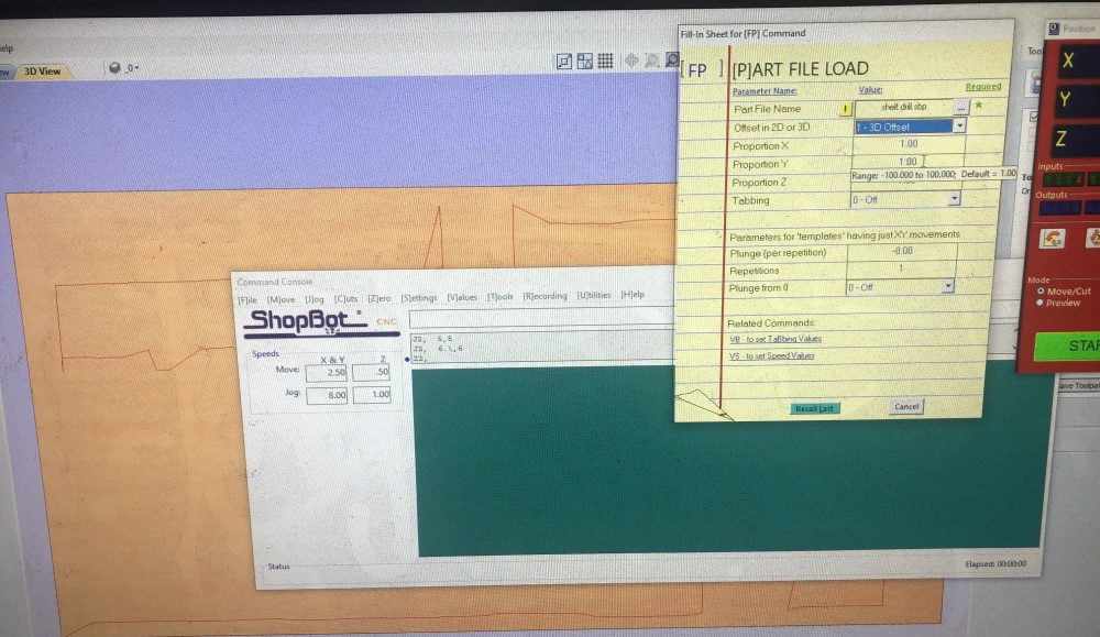
As you can see, the drill bit created holes in the wood. This allowed me to see where I needed to screw the rest of the screws in!
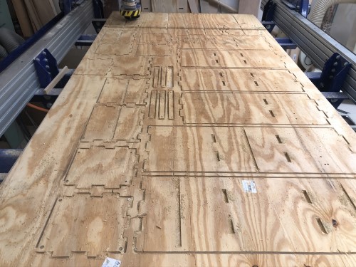
After doing that, I loaded the real toolpath that would cut out the pieces of the shelf. I homed the machine in the x and y
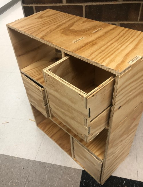
The final product:
After that, I briefly ran the hand sander over the entire surface of the wood. I removed all the screws, and since there were so many pieces I quickly scribled their names (according to the fusion file) on the top.
It actually took me a really long time to hammer all the pieces together. The tolerances were very tight (they probably need to be loosened in the future) and I had to prop pieces up against a wall so they would not budge while I was hammering in the other pieces with the mallet. This setp was actually terrifying, I had to use a lot of force to get the finger joints to lock together, and I could see pieces of wood splintering off as I did this. I was afraid I was going to somehow knock an entire finger joint off.
Despite labeling the pieces, I actually messed up once or twice and put int he wrong piece. Trying to seperate the pieces was also terrifying, because the tolerances were very tight, and I could see certain finger joints bending and cracking as I tried to wiggle the pieces apart.
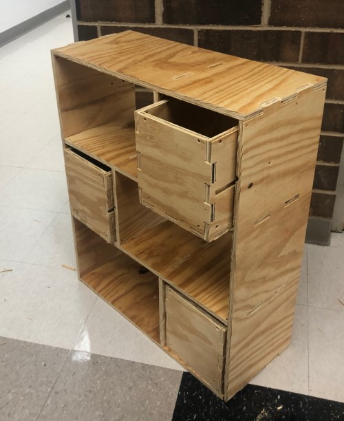
So assembly was probably the most stressful part of the project. I think I can fix this issue int he future by using some stronger wood (ie MDF insetad of just .5 inch wood) and by making the tolerances a little looser so less force is required to put the finger joints together/ take the apart. However, I did end up with this shelf,which I am pretty happy with:
I also totally abandoned the sliding part of the drawer. The drawer simply fit too tightly around the “slidey” rail part. I tried to sand down the sides for a while to see if it would work, but I eventually ended up sanding down the part that had to stay firmly affixed to the side of the drawer too, and it became too loose. Sanding it down was not a good idea. In the future, I think I could modify the parameters a bit so that it fits well off the bat, and that would help solve the issue.
I will probably try to paint it eventually to cover up the spotty pieces of the wood. In the future, I will fix the tolerances issue described above. One of the most challenging parts of the project was visualizing what the CNC machine could do/ could not do in my head before actually laying the parts flat and exporting the DXF file. think now that I have gone through this process it will be a bit easier in the future, but I also think it will be helpful if I simplify my designs and work on flipping between a flat view and the 3d model by scrolling through the fusion timeline so I can better assess my work as I make it.
I was able to overcome the error
Group Assignment
The group assignment this week was to test the runout, alignment, speeds, feeds, and toolpaths for our machine, the CNC Shopbot Alpha. We were unfamiliar with most of these terms when starting out, but were able to design objects in Fusion and cut them out on the shopbot to test them. We used a tool called Aspire to take out 3d fusion objects and create the toolpaths for our objects.
I specifically contributed after the files were designed, by helping figure out the Aspire Interface so we could make the toolpaths, setting up the CNC machine so it could mill the toolpaths, and troubleshooting the toolpath errors. You can find more information on what the team did as a whole on the group website.
Fusion file download:
.CDR of Faces from Fusion File
Aspire File (includes both the drill toolpath and the normal toolpath)