3. Computer Aided design
This week’s assignment is to model our final project with Computer Aided Design (CAD). We need to experiment with a variety of different types of CAD, including 2d, 3d, rastering, rendering, animating simulating… and more
I also switched up my project a little bit. My original plan was to make an “inverted” BB8, with the head being the holonomic motion component and the bottom being a normal robot. However, for the sake of simplicity, and because being able to say i built bb8 seems a lot cooler the more I think about it, I decided to start making that instead.
I was able to find the Bb-8 patent online. That is where I started my search for how I was going to design this. I figured 2D would be a lot simpler than 3D (I have a lot more research there, which was very helpful to see.) so I started with that.
2D Design
For my 2D program I decided to use inkscape, a vector program for 2D design. I have never used it before, but I know it’s downloaded on all of the computers at my school’s engineering lab, so if I ever am not using my laptop I will have an easy way to access it (that is also why I chose Fusion 360.)
I’ve never used this before.
For my 2d design, I simply drew my general idea for a design as a cross section. I will get more detailed in the 3D part.
I started by navigating into the document properties, but I didn’t really have any ideas for how I wanted to change them so I left them mostly be. But that menu is in “File, “Document Settings” and allows you to change document settings, preferences, and more.
I did find the page incredibly small, so I started pressing CTRL + to see if it zoomed in because that is usually what zoom in is. That did nothing but hitting the + and - keys scrolls in and out. To “pan” across the page, simply use the scrolling bars at the bottom and left side oft the page.
I dove into trying to make a circle, when I realized I didn’t know any of the tools I found this [tutorial] (https://inkscape.org/doc/tutorials/shapes/tutorial-shapes.html) started by making a circle. I used it for reference but only read over some of it. The circle tool is on the right hand side toolbar, and simple looks like a circle. a circle. Holding shift and ctrl I made it center point, and I made it fit the ratio I was drawing it closest too (1:1)
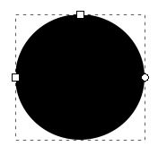
If I click on it I see three boxes appear around it. The top and left one are for scaling, the right one takes pieces out of the circle.
After I started playing around with these three things I eventually just deleted my circle. The next time I tried to draw a circle (using the same steps) it came out like this:
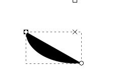
I wasn’t sure what to do here so I started pressing buttons. Somehow I found the right ones: After creating this circle and selecting it, the last row of the menu bar looked like this:
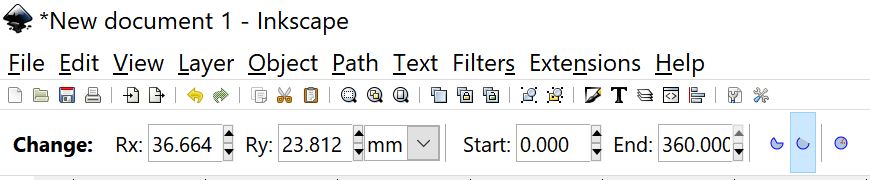
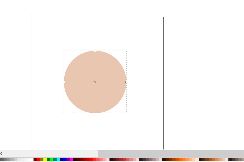
However, all of the values had weird numbers in them. I changed “Start” to 0 to see if that changed anything (because the beginning is always a good place to begin!) and the end changed itself to 180. I changed that value to 360 and I got a normal circle again. Changing the “Rx” and “Ry” values allowed me to change the radius of the circle. I just decided to change it to 50x50.
At this point it had moved across the page so I googled [how to move inkscape drawings] (https://www.tutorviacomputer.com/inkscape/the-selector-tool/#moveobjects) and there are a few different ways. I chose to locate the selector tool (Mouse icon, first one down on right toolbar)and drag objects.
I also noticed a line of colors at the bottom. AS long as the object is selected, clicking on a color will change the color. Bb8 is orange so I made this light orange. The color is kind of ugly but at least it stands out for now.
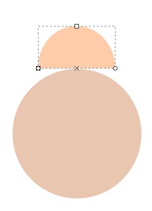
I moved it to the middle then made another circle (for bb8’s head) on top. This time I made the start 180 and the end 0 to make a half semicircle, with the curve on the top part. I dragged it on top of the other circle with the selector tool and changed the x and y radius so it looked like bb8’s head.
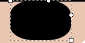
I then drew a series of rectangles using the rectangle tool (right toolbar, looks like a rectangle- not a cube; the cube makes actual cubes with perspective, which isn’t what I was intending to do here. I made the rectangles to represent the the base of the interior board, as well as the counterweight of the bottom, the stem holding the magnet on the top of the body, and the magnet sitting on the bottom of the head. I was able to use the upper toolbar the same way I used it with the circle, and used this to make all the rectangles nice dimensions. I liked these rounded corners and wanted them all to be uniform but you can change the roundness of the corners by dragging down the tab that appears in the upper right corner of an object that you have just drawn. I did it to demonstrate:
Ctrl+ V works as undo
While in the selection tool you can also manually input the x and y coordinates, where you would have otherwise entered the shape value information I mentioned earlier.
I then created basic mecanum wheels. I created two rectangles next to each other with round edges edited and made lots more rectangles, edited their round edges. I then rotated the rectangles to 45 degree angles by clicking on them in select mode then clicking on it once more. Do not double click, this gets you back to the menu you have while in the rectangle tool (but this is also useful to know for later.) on the object with the select tool then dragging the exterior edge in the direction you want it to turn. It tells you the value of the angle you are creating at the very bottom, and will snap the angle to the closest value that makes sense if you hit the Ctrl button, so you don’t get stuck going in between 44.9 and 45.1 (phew).
I continued to use all the steps discussed above to change the size and position of these “wheels.” I didn’t really need to do this, but learned how to flip the other wheels horizontally by going to the top “Object” menu then selecting “Flip Horizontally” on the dropdown.
I copied and pasted a lot of these elements with Ctrl + C and Ctrl + V so I wouldn’t have to meticulously edit all the shape values.
To finish everything off, I tried drawing an antenna with an amorphous shape on the top of the head. This isn’t something I necessarily need on the outside but I wanted to practice with splines and harder shapes.
Two options on the right bar menu have what are known as “Freehand” and “Bezier” curves. Freehand is self explanatory so I chose that and found that you have to edit the curve by changing a line at the end of the curve. Note: To activate the tool, you have to press and hold down as you place points, or you will get a straight line. I found this to be hard. I had to keep undoing my work and eventually all I got was this simple curve. I also learned that if you don’t close the shape off, inkscape will just delete it. It’s very basic but I’m glad I at least know what this is now.

To add a few details, I wanted to pur black rings around the body and head.
To do this I made two circles, one of 53 mm radius and the other as 51mm, so I could layer them on top of each other and delete a section
I did this by going to the “Path” menu and selecting “Difference.”
I later decided to redo it but thicker, and do it again with the head and got this as the final product:
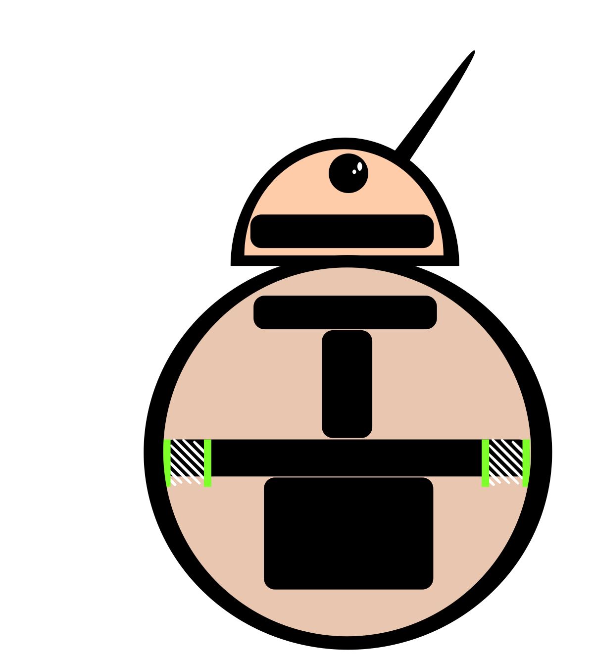
I added an ellipse and the whites of an eye (not usually seen on a robot) because I thought it was cute.
This is how I introduced myself to inkscape. I feel like my work is more of a drawing than an actual design, but I’m ok with that for now because I think I was able to familiarize myself with the important tools and start learning how to make shapes.
3D Design
I decided to use Autodesk Fusion360 I started this week off by downloading it. I plan to use it as a starting off point for my designs. I do have some experience in it, but everything I have done is very simplistic and does not include many complex features.
Because I am shaky with CAD I started by flipping through this [tutorial] (http://help.autodesk.com/view/fusion360/ENU/?guid=GUID-1C665B4D-7BF7-4FDF-98B0-AA7EE12B5AC2). It’s very long and I’m not sure how much of it I will and will not use, so I started flipping through it but did not watch the videos, except for the one labeled “Design: Sketch: Concepts” because I figured this is what my design will start with., I plan to reference it as I see features I need.
I also did a “Construction Geometry and Constraint” tutorial because I always spent a long time doing these in class, as I never really taught myself the proper way to do them.
Designing in Fusion
Basic designing in Fusion : To start everything, You have to download the program and on the left hand side you will see a menu. In the upper right corner is the option for “New File.” Once you are there the most basic way to start is by navigating on the upper bar to “Solid.” To start a drawing, go to “Create” and under the dropdown hit “New sketch.” Then you select an axis to draw in, you can only do one at a time, and start selecting tools like rectangles and circles. Each shape has different options on what to draw so you can create different sizes and shapes.
After you sketch an initial shape, you should add dimensions and constrain it. Dimensions tell you the size. Add them by going to “Create,” “Sketch Dimension” after having already started a new sketch. Note that the menu options look different when you have created a new sketch versus when you are just in the general menu.
Constraints take different sketch objects and do things like make their sizes equal, make them perpendicular, etc. Usually you just select the constraint, select one object, then select a second one to apply the constraint. The first thing you select will not change, the second thing will change around to do what the constraint told it to do.
Most of what I needed to figure out I learnt as I drew, but the tutorials definitely helped. If I had to google anything, I linked where I got my answers.
I figured the holonomic motion system (what allows bb8 to move in all directions) would be the hardest to make, so I started by doing research.) Here are some of my references, I mostly looked at these to glean aspects of the design but some are full of tutorials and explanations. The wheels seem to be the hardest thing to make.
- How BB8 works
- Why Omni wheels work
- Mecanum wheel solidworks tutorial
- Mecanum-Hackaday
- Laser cut omni-wheel design
- Another Mecanum Example
- How to control Omni-wheels
- Comprehensive but with hard math
The biggest thing I used these for was for how to design the wheels! Many of those sources are labeled omni wheels but what I need (for the four wheel drive I proposed- which I want to stick with because I think it would be the most stable) uses something called mecanum wheels. They both produce holonomic motion (that is, free motion) but mecanum are what you need for 4 wheel drives.
On to the actual design: I started with the wheels first, because I thought they would be the hardest and wanted to get them out of the way. I hit a snag on the wheels (and I wasn’t on wifi so I couldn’t google a solution) and so I started making the base then the head. After that I finished the wheels, then did the body. Looking back, I probably should have done the entire thing with some sort of process in mind, but it worked for these purposes.
The Wheels:
Refer to the many links above to see how I made these. They are not my original ideas.
I started by drawing the basics for what I will refer to as the “rollers.” They will go where the typical treads of a tire go on the wheels, so when the wheels turned they will be able to move in any direction.
In the tutorial, one corner of the wheels were drawn so that’s what I did. I tried to draw the actual rolling part (outside) and the interior circle where an axle would go through, with a little border between them. I used the line tool for straight lines and the spline tool for curved lines (Both found under `Create”). Both place a point when you click your mouse. I placed a lot of sketch dimensions so I could modify this later and made some parallel and perpendicular constraints. I then drew a line directly next to my sketch, and navigated to the “mirror” tool (Found by going through “modify” and selecting “mirror” then selecting the straight line as the axis the object will be flipped over.)
So this:
Became this:
I then selected “Finish sketch” on the right hand side of the menu bar. You may notice a straight line under my sketch. I did this so I could use the revolve tool, also under “Create.” I selected “Revolve” and noticed a box pop up with actions I could perform. It allowed me to choose profiles, so I clicked on the faces of the sketch I made to select them, and chose the line as the “Axis” they would revolve around. This is generally how most tools work in Fusion, besides the basic geometry sketch tools.
When I clicked enter my design suddenly became an actual wheel.
I now had a “body” for my roller.
I realized that if I looked on the “Browser” menu on the right side and looked under the “Sketch” menu I could select my sketch. I can also look at bodies, components, etc. By right clicking on the sketch name under the menu I could then select “Edit Sketch.” Anything I changed in the sketch would be reflected in the body I had made with the revolve tool. I changed my design slightly.
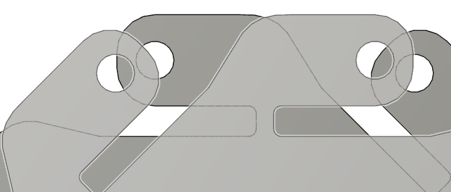
I then began to draw the prongs and wheel that will hold these rollers. The wheels of holonomic motion look like normal circles, except they also hold the rollers at a 45 degree angle. I started to make one as drawn in the tutorial By repeating the same steps as before but this time with circles and more complicated lines. You will notice that there are 8 of the same pattern.
I didn’t draw them all separately, after drawing one I navigated to “Create Circular Patterns’ ‘ (Found under “Create,” “Patterns,” “Create Circular Pattern” and chose my sketch. I selected the midpoint of a circle I had drawn this part of the wheel around as my center, and selected 8 as the number of duplicate sketches I wanted it to make. I extruded the entire face (select a face and press the key “E”). It turned out like this:
I was able to drag parts of my sketch around so they all linked up. This is a very helpful tool!
After finishing that I put it all together. First, I scaled them all so the openings that had to go together would be the same size. I also went back in and modified a couple of the sketches too,(as described above) in order to make a scale that I thought would actually look good in real life.
I did a couple of calculations to figure out that the two bigger portions of the wheels (circles with weird shapes sticking out) needed to be slightly bigger than 150mm apart so the wheels could fit between them. I made the distance 155. Then I rotated it 180 degrees, essentially making the copy a mirror of the original.
I need the angle between each of the holes to be 45 degrees. Unfortunately, I completely glossed over this while designing my wheels. I’m going to need to rotate all the heads of the wheels by 45 degrees.
To do this I made a new sketch on the face of the wheel holder. I drew a line through every protruding part and used “Modify,” “Split body” to detach these parts of the body. The lines acted as the axis that split the body. Make sure to deselect “extend axis” or it will cut other parts off.
I then tilted each of them 45 degrees inwards. To fill in the gap I had to perform a loft (“Create”, “Loft”) but it didn’t work because the faces were touching. So, I moved the detached body up the smallest amount it would let me and retried the loft. This time it worked! I also “FIlleted” the loft (“Modify”, “Fillet ‘’. Then you select the edge you want to curve out.) as it came out a little clunky.
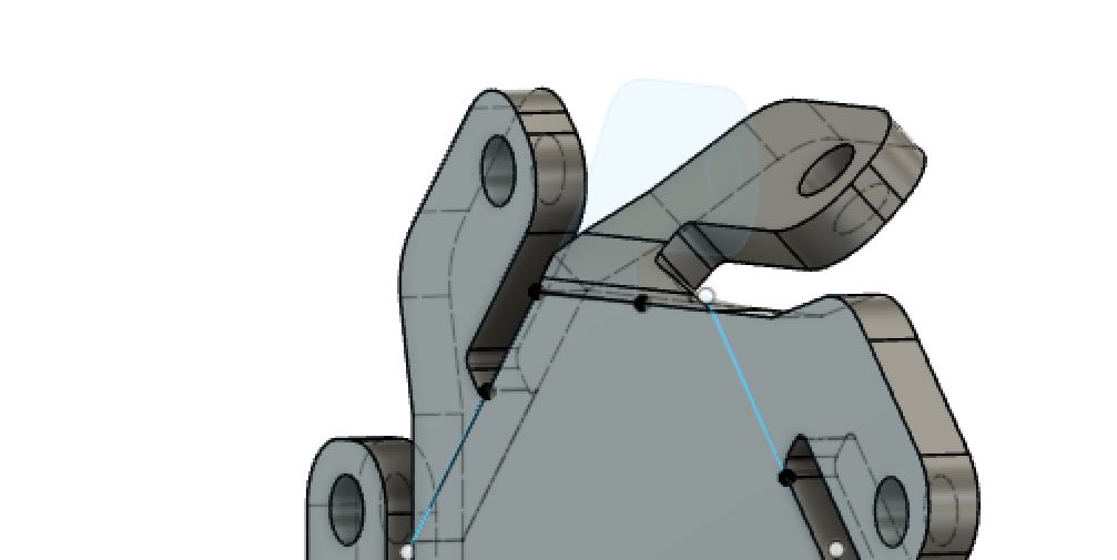
I then did this to all the remaining sides.
I had aligned the two sides of the wheel before, but I deleted that body and redid it with this altered design (I didn’t want to re rotate, loft, anf fillet all of these)
I aligned them so they each had the circular hole bit facing another circular hole. This way, I could move all the smaller rollers to go in between them.
Redoing the wheels
I messed up!! I bent the wrong section. Now nothing lines up. The wheels need to be bent a lot higher up the spike.
I used the timeline feature to undo everything I had done with the bends. I was really upset about this because it took me a really long time. Anyways, I redid the entire process of splitting the bodies and rotating them, and then lined them up. After that I moved the smaller rollers into the center of them, made sure all the holes were lined up, and created a cylinder in between the three holes. I placed two circles on the edge of the cylinder and extruded them, they cap off the cylinder. THis is what I ended up with
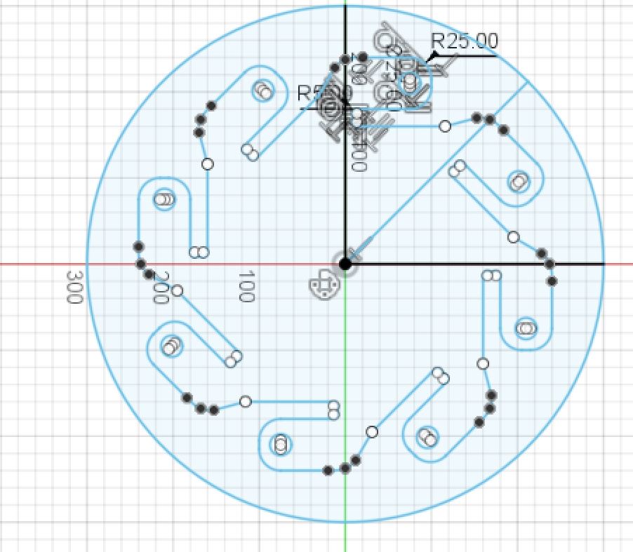
After that I created a circular pattern of 8 with the roller and cylinder setup, and that is how I made my wheels.
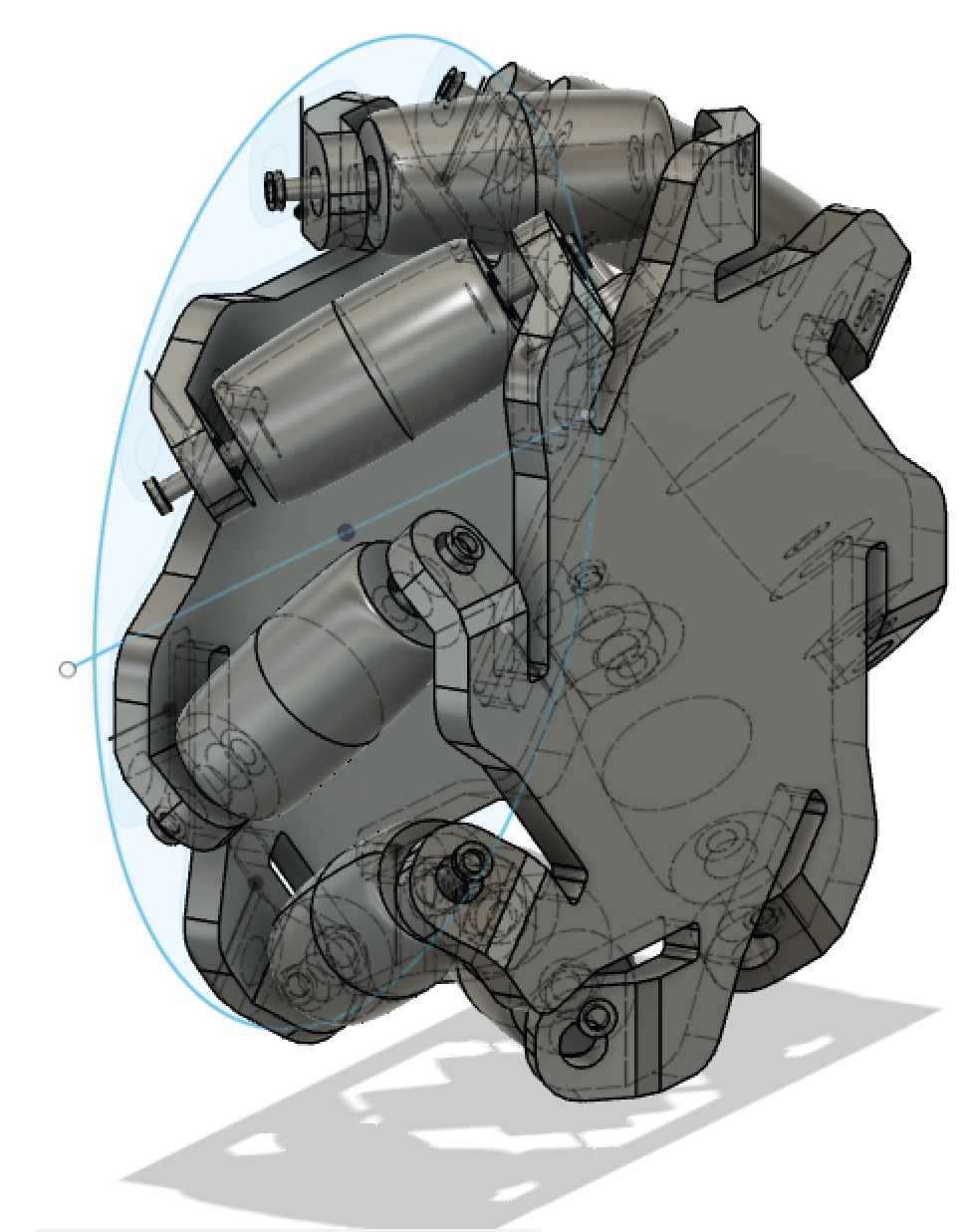
Finally, I moved on to assembling everything. I took the cylinder from earlier and shrunk it to what I thought would be an appropriate scale.
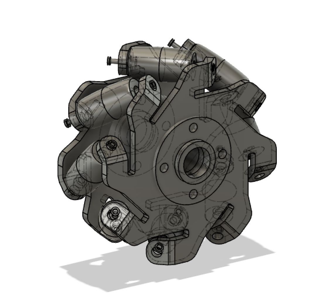
I then moved the cylinder with the hole over to the center of my wheel. I made sure it was centered by moving it using point to point moving, and selecting the origin as the center of the cylinder and the target as the center of the circle that was circumscribed around my wheel.
The hole in the middle filled in, so I created a new sketch and a circle on top of the original circle. Then I extruded it backwards to cut out the part that became filled in.
The Base:
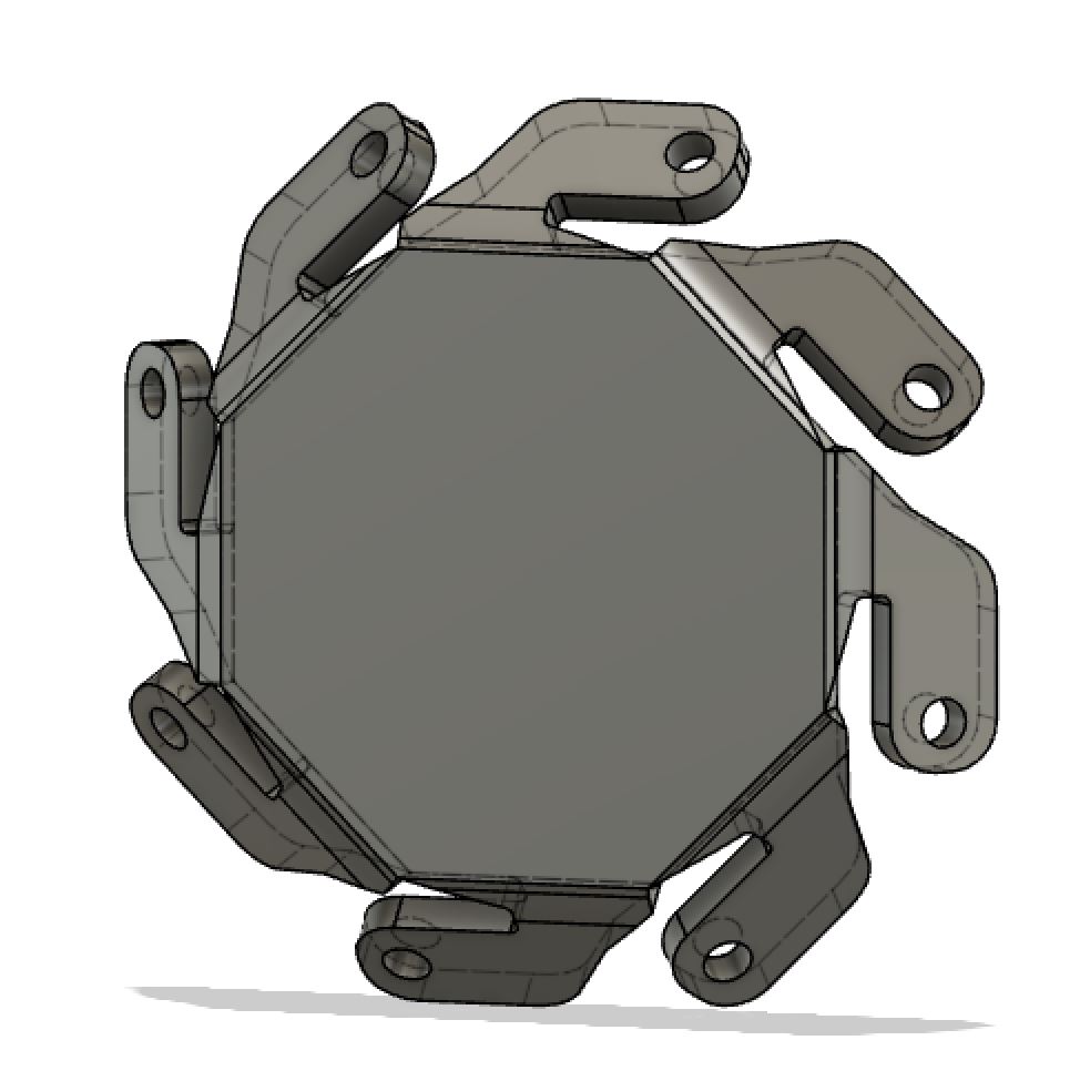
This was very simple. I started a new sketch and drew a rectangle. Then I drew two lines going from either corner. Around this framework I drew more lines like bubble letters, keeping in mind the dimensions. I then selected the trim tool (Found under the “Modify” menu) and cut the overlapping lines off. I then hit “E” for extrude and made the entire thing 20 mm high.
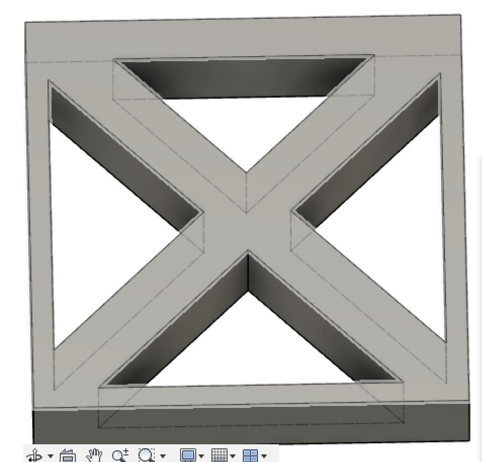
I did discover the “Create new components” tool under “Create” with this sketch. It made my base look like this:
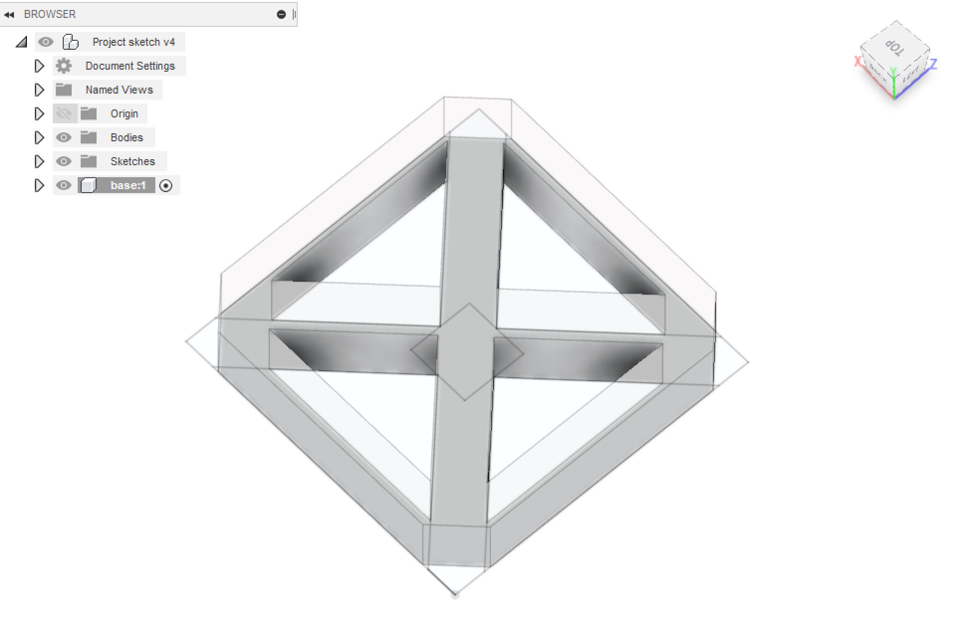
I will use this to keep very large amalgamations of sketches and bodies organized.
Head:
Now I decided to actually make the bb8 shape. I imported a photo of him cause I can’t really draw freehand. I traced him and made a revolve.
I inserted a background layer canvas of BB8 because I don’t trust my ability to draw it “freehand” (even with the tools in CAD) and make it look realistic.
Found a way to do that [here] (https://knowledge.autodesk.com/support/fusion-360/learn-explore/caas/sfdcarticles/sfdcarticles/How-to-Import-an-Image-as-an-Attached-Canvas.html)
Go to “Insert,” “Insert canvas,” “select from computer” and navigate to your computer. There are other settings like opacity, but I didn’t really mind so I just scaled it up slightly and left the image be.
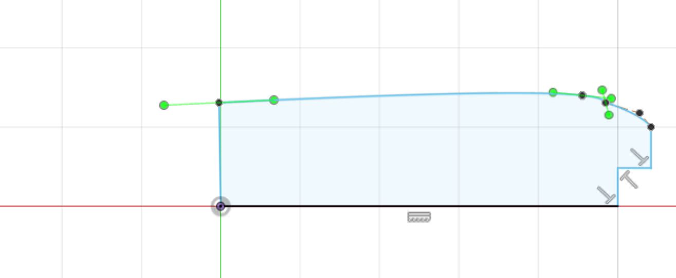
I just used splines to trace the outline. I just zoomed in really closely to make sure I was hitting the actual images.
I copied a couple of splines from bb8’s head and dragged them down for the details on the rims.
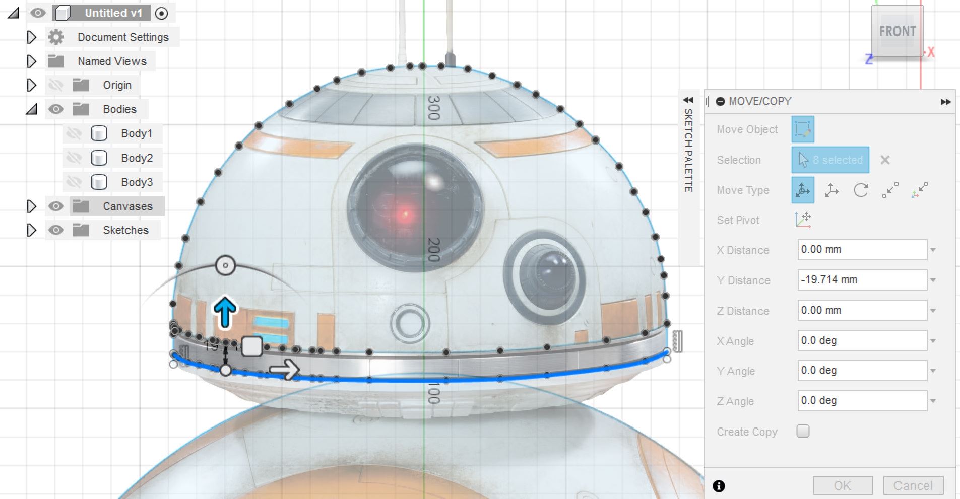
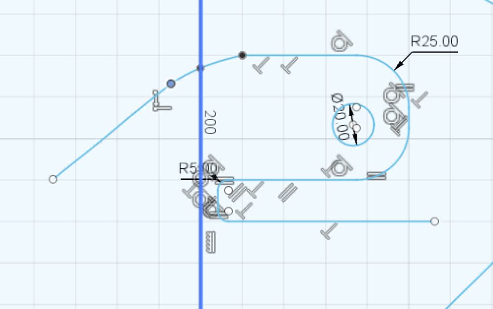
I want to make the components separate parts (because they won’t be connected on the actual final product) I recorded the radius of the circle (300 mm) and deleted the part of it that didn’t overlap. I am keeping the part that does overlap because I need the head to have a round part so it moves easily.
I tried to make it revolve around a line I had placed on the y axis (I started the design at the origin so the y axis would be centered) but realised some of the faces weren’t selected. I didn’t close all the splines, so I had to go back and fix them.
It was still throwing an error, because the two sides obviously aren’t symmetrical and trying to revolve would have had some weird overlapping and the program wouldn’t let me do that. So, I went back in to edit the sketch and used the trim tool to the side I thought was worse. Then it worked.
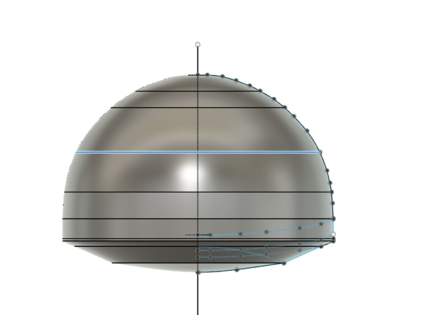
However, there were some lines projected over the body. When looking closer, these were the points where my drawing wasn’t very smooth, and in some places the curve even flipped from convex to concave, so I went back in again to try to edit and smooth out the lines. I just had to edit the sketch, and then the changes would propagate through the program and change the body.
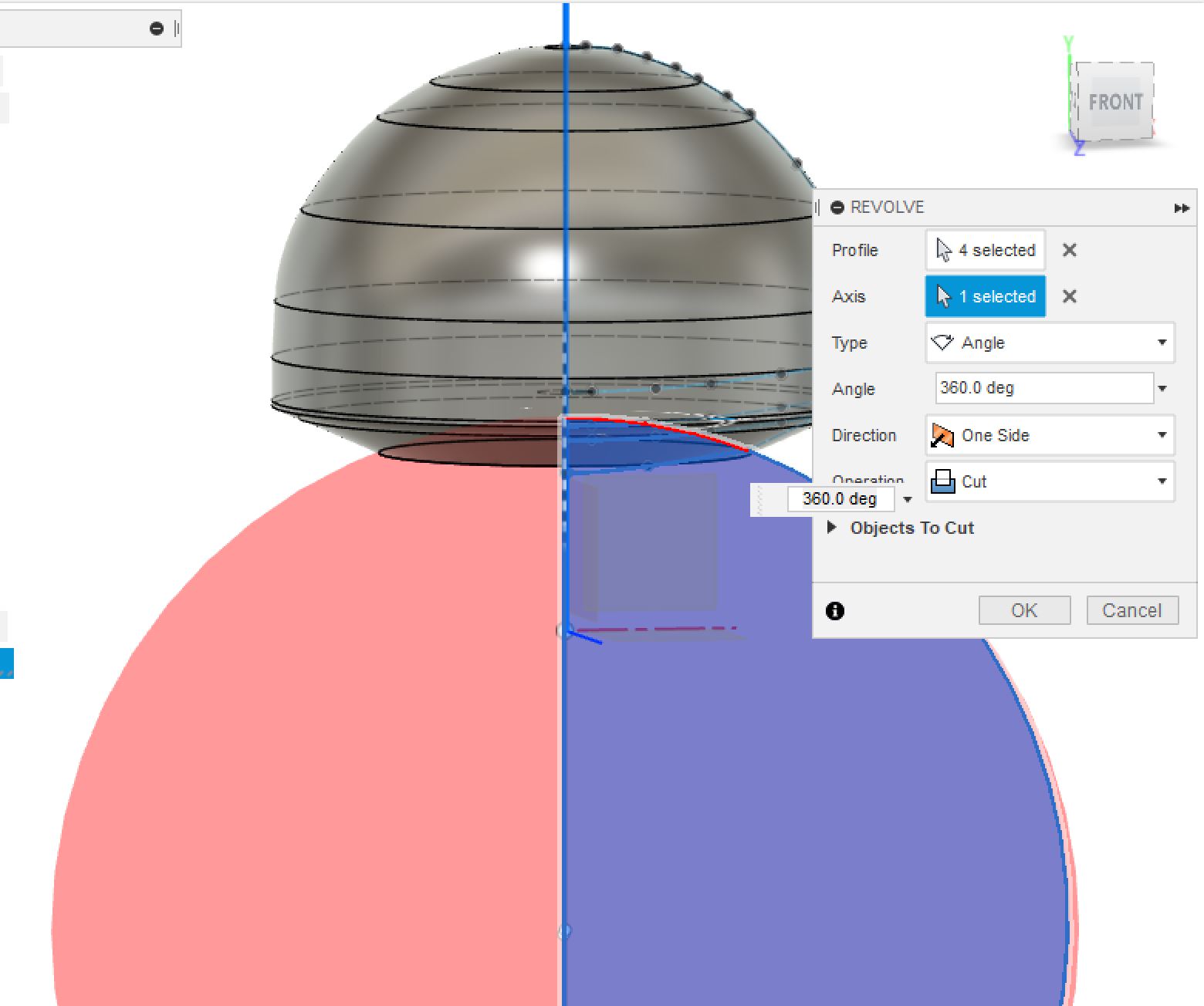
I actually then put the big circle back into the sketch. I realized the revolve tool (when overlapping with other bodies) didn’t just have to create bodies, it could also cut bodies. So I redrew the circle, cut out one half so it didn’t cross the revolving axis (here I discovered it had nothing to do with symmetry, the circle has to be perfectly symmetrical since I used the circle tool. The revolve tool won’t work if your sketch crosses the “revolve axis” that you try to spin it around. I misinterpreted the error.) So then I used the revolve tool, and was able to hollow out the head.

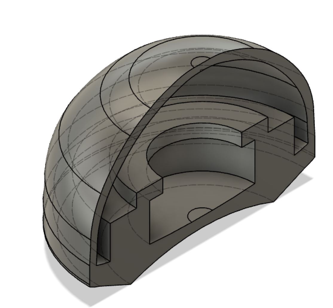
Now I have to focus on the interior portion. The way the head will connect to the body is with a very strong magnet, but the magnet will need some sort of flat base to be on.
I copied the spline and moved it down the x and z axis 15mm. I needed to create a revolve after hitting the “finish sketch” button, but then there would be other components surrounding it and I wasn’t sure how to select the face. So I selected the face, then clicked “Finished Sketch” and it remained selected. I was kind of surprised this worked but it did. Then I used the revolve tool.
I know the magnet will need to be held in place by something, but I don’t know what size it needs to be yet. I created a rectangle in the sketch and a smaller rectangle on top of it. The hope is that the magnet will fit under this, and the rectangles will be around it so no matter how much the magnet moves, it won’t fall out into the other section of the head.I carefully selected the rectangle so constraints like coincidence would already be applied, and if I wanted to change the sketch dimensions the lines would depend on each other. I then decided that for now, because I don’t know if the magnet will be circular, square, and what size it will need to be, I just left it like this. This part will most definitely change.
I made the head a new object by selecting “create” and “new component.”
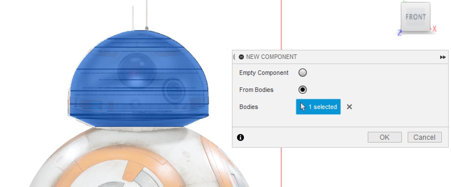
For the purposes of seeing the inside, I made sure I had saved everything then I split the body so I could see inside. By navigating to the “Browser” menu, going under components, component 1, and then selecting the eye icon on one of the bodies, I was able to make one of the bodies transparent so we could see inside for documentation purposes.
That’s the head! I did some of the work with the wheels and base earlier, but then I moved on to creating the body
Body:
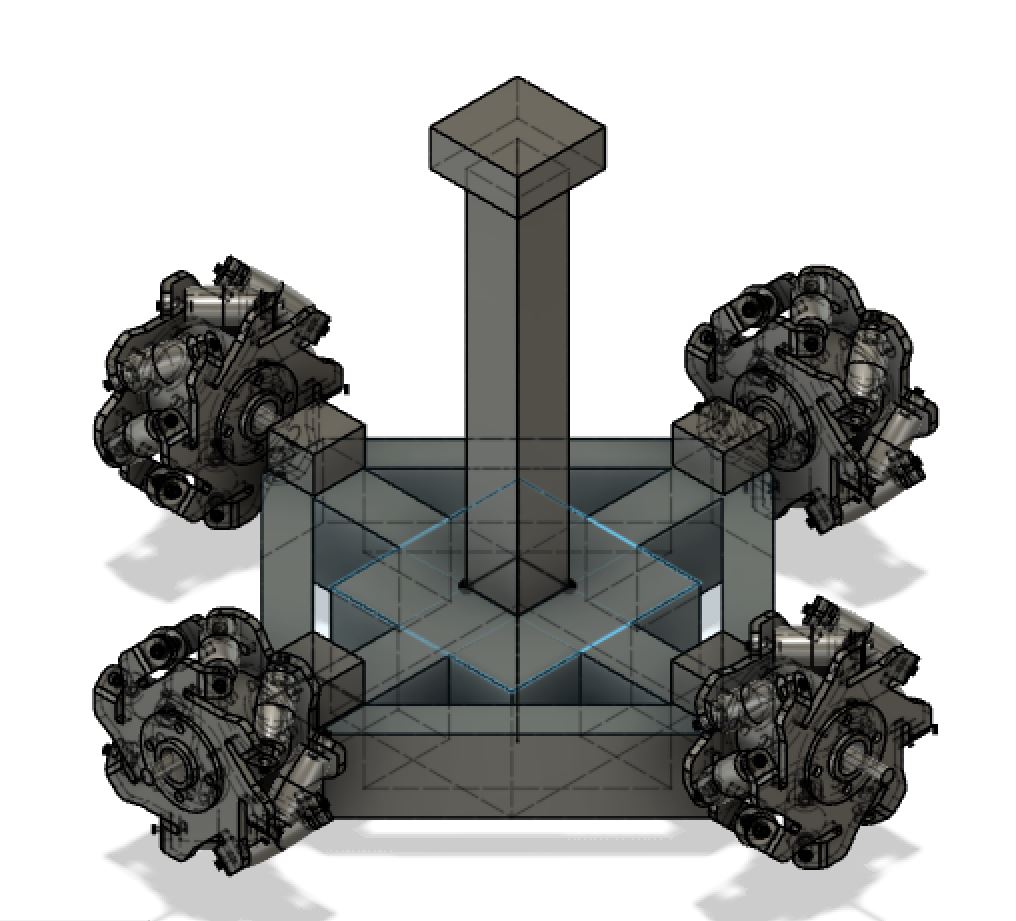
I had to add a few more details to the base as standin for where the motor and axle will be. I just used a rectangle and a cylinder. Then I copied the wheel four times and relocated one of each of them to make it look like they were “connected” to the motors.
**Note: since there are so many components in the wheel I grouped one wheel with “Modify,” “Combine” so I could move it easily.
I also added a large rectangle at the bottom of the base, the “counterweight,” and a large stem with another rectangle for the “magnet” at the top of the body’s framework.
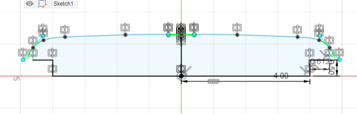
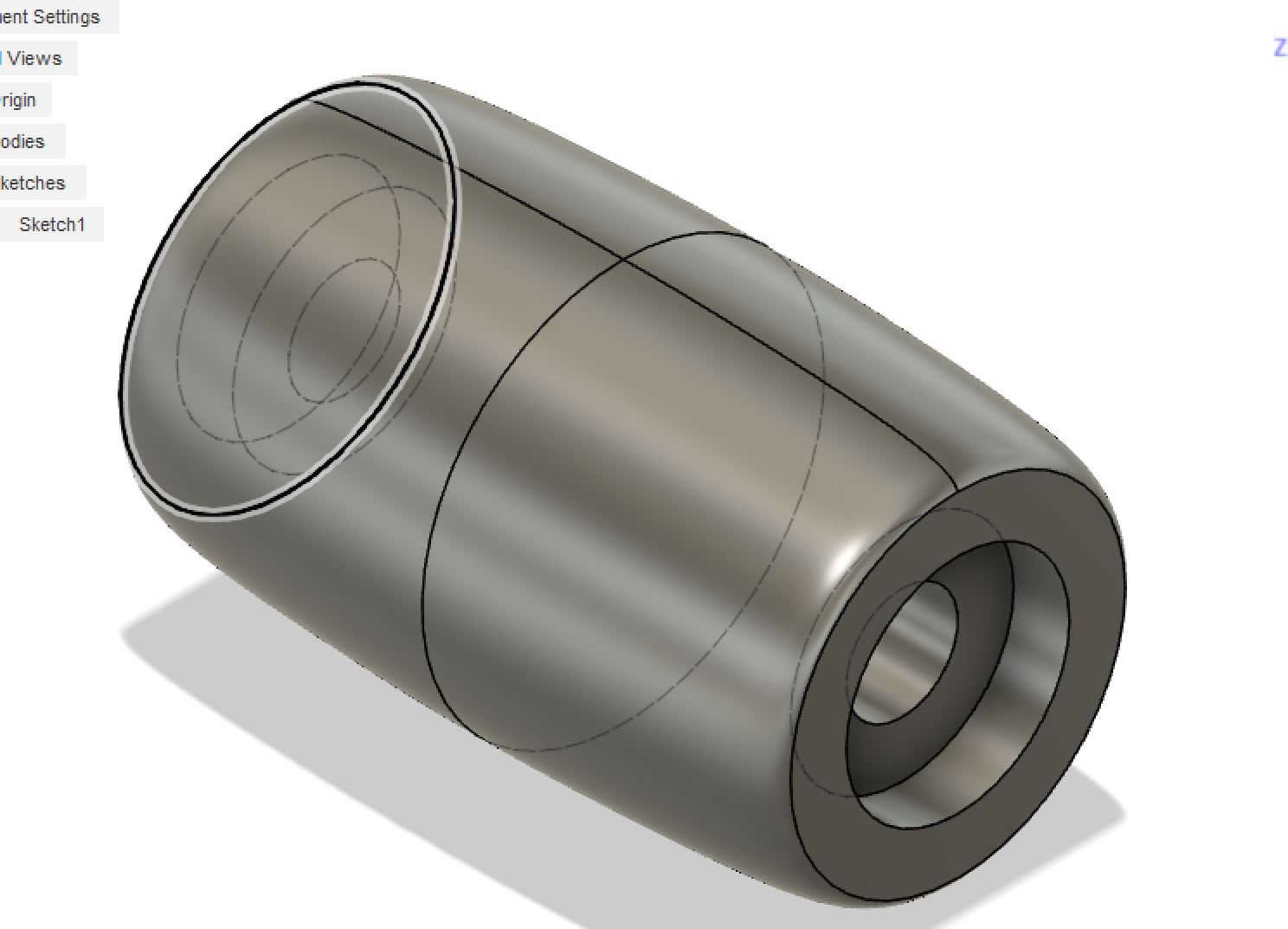
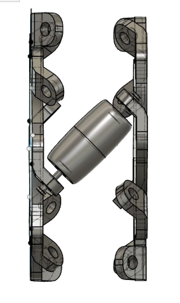
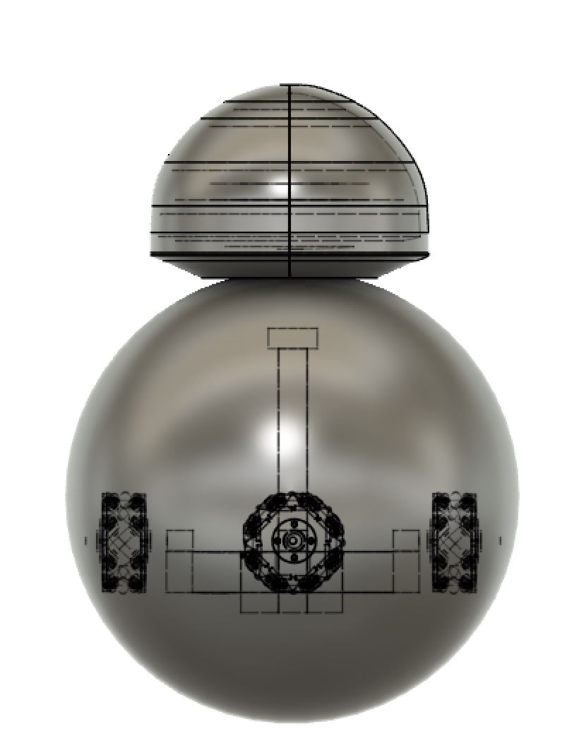
Then I draw two circles circumscribed around the center of this. One circle is slightly bigger than the other. I drew a line in the middle of the circles andI trimmed one half of the circle so I could use the revolve tool to make the outer shell. I moved the head of BB8 and voila, I had put my droid together!
Here is a cross section view:
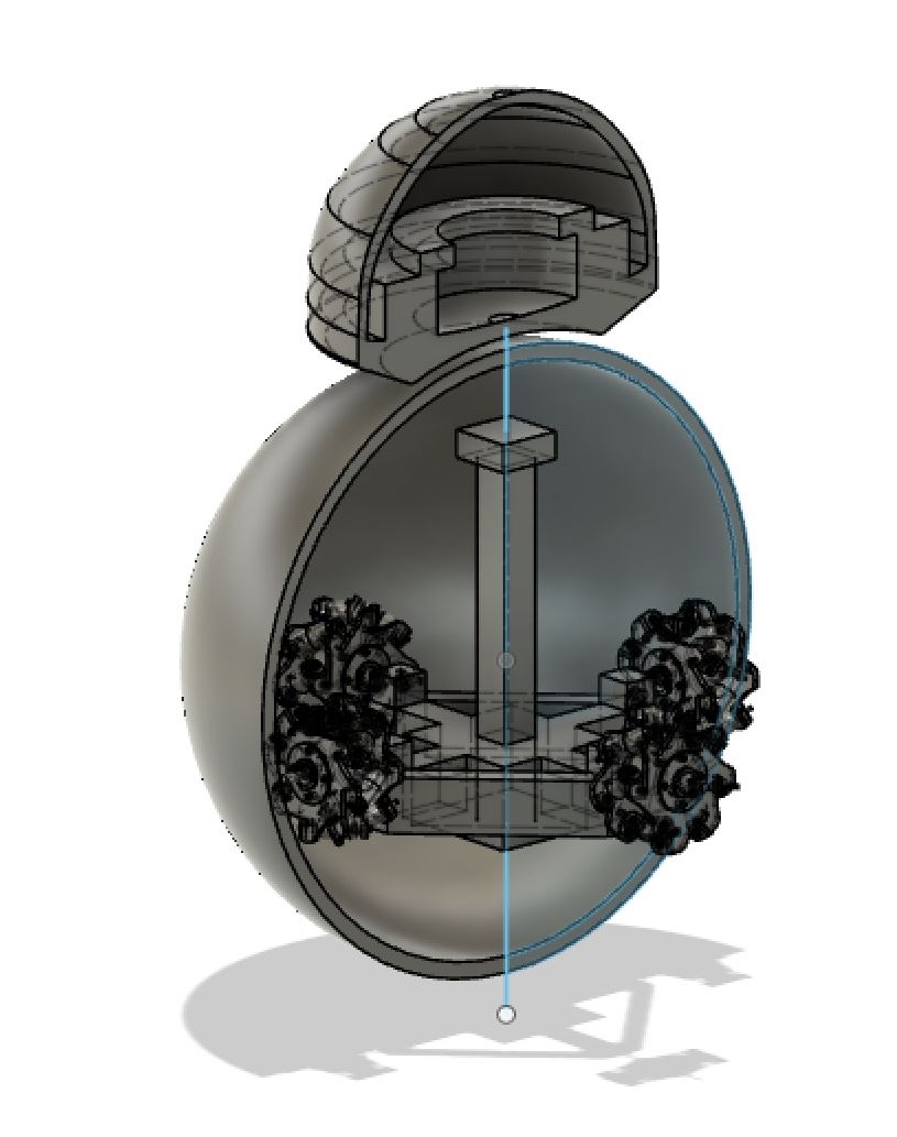
Final Product:
(right now it is being displayed with half of the body being cut off in V9. To view it as a full body, toggle back to V8.)
Blender Physics Simulator
The final thing I checked out was Blender Physics Simulator. I ran out of time to test it with my own creations, but I explored other people’s work and learned that it uses what it calls a “Bullet Physics Engine,” to simulate real life physics in your designs. I didn’t have much time to experiment with it, but I always spend lots of time wondering if my Computer designs would continue to work when I actually made them in real life. Specifically for this project, I am wondering what type of materials I need to use to make sure all the parts that rub against each other (bb8’s head and his body, as well as the wheels inside the body) will be able to move alongside each other smoothly, and also not damage the material. Programs such as this one allow you to not only design in 3D but also test them.
Other CAD programs offer effects like this. However,I really liked this one because it also offers an array of effects that can be used on much broader scales of creating games and animations. While I doubt I will be creating games, I could see myself using a physics engine to create an animation showing my designs in action and demonstrating what they can do next to high quality animation graphics.
It has been used to do many more incredible things, which you can check out [here:] (https://pybullet.org/wordpress/)
In the future I would like to learn how to make more constraints with inkscape and dabble more in Blender Physics Simulator.