Final Project
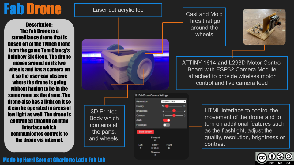
After completing each weekly assignment, we get to use our knowledge that we have gained in order to create a final product. This product includes concepts and pieces of the weekly assignments, and the great part is that the only limit to our project is our creativity. In the first week, we had to plan out what we wanted our project to be, and I have decided to stick to my original idea, which was to make a real-life twitch drone from the game Tom Clancy’s Rainbow Six Siege.
Slide and Video
Licensing
As I decided in Week 14, I will use the CC BY-NC-SA license, or a Creative Commons Attribution-NonCommercial-Share Alike. This means that anyone can use, modify, and change my work as long as they give me full credit, don’t use it for commercial purposes, and publish their new work under the exact same license that I have with mine
What is a Twitch Drone?
In the game Rainbow Six Seige, there is an operator named Twitch who has a drone which she can use remotely, as it displays live feed to her, and she uses this gadget in order to survey an area for enemies, and the drone also has a special feature, which shoots a shock darts, which can destroy cameras or damage enemies. My version of this drone will be trying to recreate something like the drone, but a little more safe so that it can be used in more places.
Inspiration
My inspiration for this project was from the game Tom Clancy’s Rainbow Six Siege, but what really made me decide on making this project was a video made by the Hacksmith, who is a YouTuber that makes cool projects where he brings things from movies, games, and comics into real life, and on one of his videos, he made a Twitch drone in real-life. My project will be different from the video as the Hacksmith used an RC drone as a base, whereas I will be making my project from scratch and will be removing the projectiles and taser (for safety purposes).
Resources and Guides
To start off, when I researched projects and guides similar to my project, and as I go on, I will update this section with links and resources that I used in order to complete my project.
1. ESP32 Cam Basic Setup Tutorial
2. Instructables similar robot
3. HTML to Hex Array and Vice Versa
The Plan
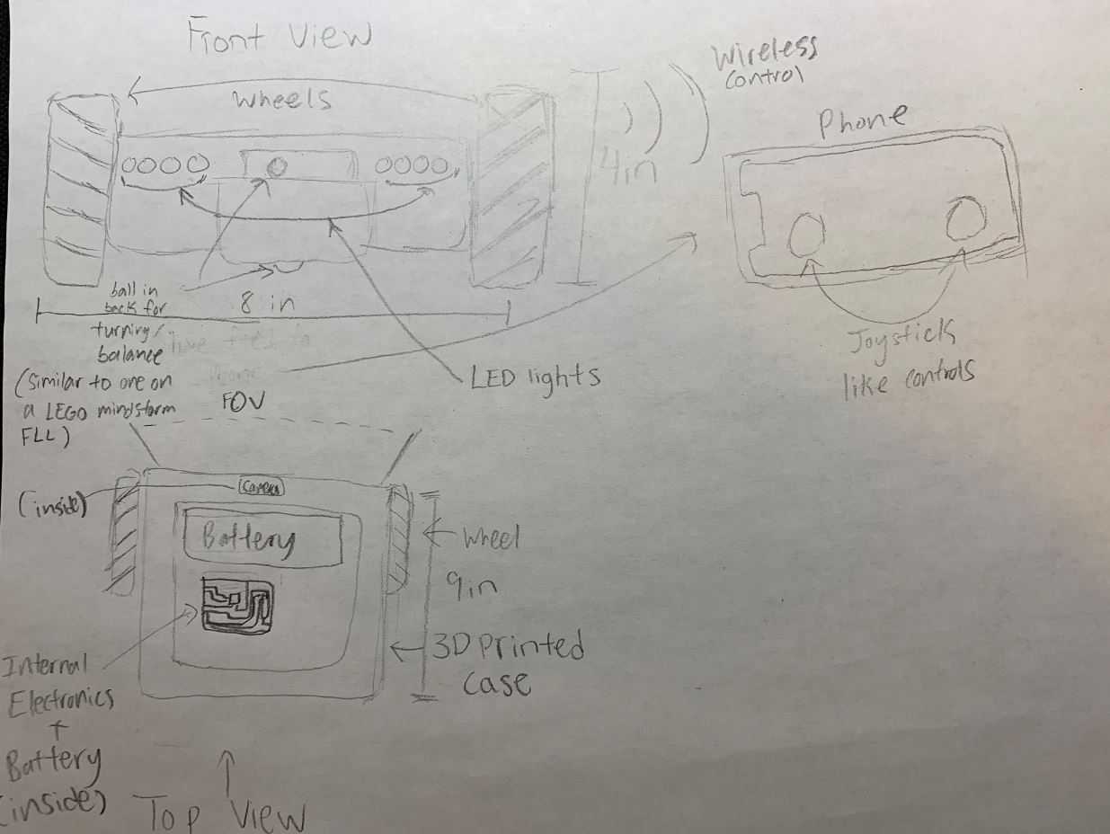
From the beginning of this class, I had a general idea of how I wanted to create this project to look like and function. Here is a sketch of what I envisioned:
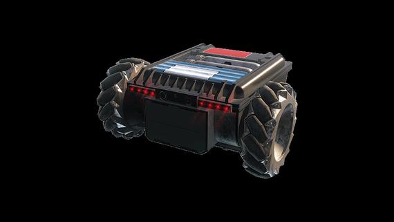
Here is a picture of the actual drone:
Here is a 3D model of what I plan the drone to look like:
I was given the advice to try to shape some of the weeks towards my final project, which looking back, I am glad that I was given this advice as it doesn’t cluster everything for the end. Down below is a list of what I had planned each week to contribute towards my final project.
Week 3 - Designing the body that I will 3D print for the drone
Week 12 - Figuring out how to drive the motors for my drone
Week 13 - Creating an interface that would control my motors
Week 16 - Mold and cast the outside part of my wheels
These weeks were very helpful in getting pieces for my final project, but I still had some ways to go.
Stages
After making things such as a Gantt chart and trying to make a to-do list to organize everything, I still felt that I wanted to make my project easier by breaking it down, so I decided to create stages for my project. Down below will list all the stages of development for my project, and they will be updated as I make progress
Stage 1 - Using the ESP32 Camera Module p.1
One of the most important things that I still had to complete was the live feed aspect, so I decided to do some research on the types of cameras that I could get.
The day that we got back to the lab, I talked to Dr. Harris, who was very helpful in explaining some possible routes that I could take, especially using the powers of processing. I learned that I could use processing in order to not only control my drone but if I got an IP camera, I would be able to display a website on my app, which would be able to provide live feed to my camera.
After looking into some cameras, I came across the ESP32 Camera Module, which is an ESP32 module which uses the OV2640 camera, and has the capability to steam video over the internet with facial recognition (a feature that I am not using right now, but might use in an updated version in the future).
With this, I also found out that I could control my motors using the ESP32Cam Module, so I decided to order it. I will update what I do with this module in a later stage, sort of like a part 2
Stage 2 - Getting the motors to spin using an Arduino
For my project, I decided to use Brushless DC motors (BLDCs), as they are fast,quiet, and efficient and are also used in many RC cars. In my Output Devices week, I created a board that could control a BLDC, which looked something like this:
Here is the code I created and used (after calibration):
#include <Servo.h>

Servo ESC;

void setup(){
  ESC.attach(9);
}

void loop(){
  ESC.write(90);
}
This turned out well, and the motor spun like this:
I also created an interface for the motor during my Interface and Application programming Week, which turned out well, as I was able to get three buttons to control different speed levels. I mentioned in the week that the next step for me would be to create a slider interface, and I will be working on that in my next stage.
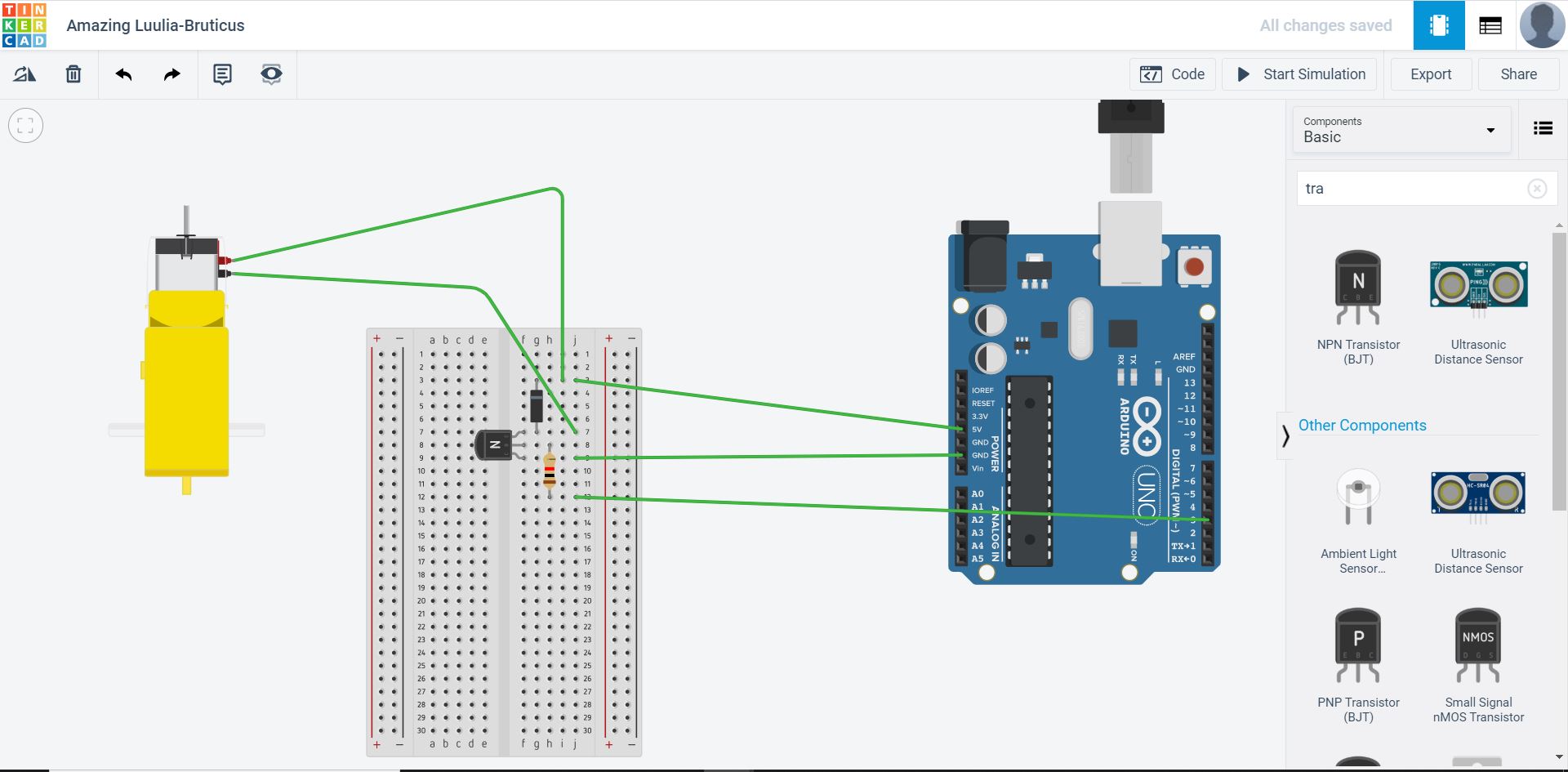
Update 1: Initially, I had planned on using brushless DC motors in order to drive my drone, but as I progressed in my final project, I realized that a regular DC motor would be better for my use, as the BLDC was extremely fast and was harder to get precise control with, so I decided to use 2 plastic DC gear motors that I found in the lab. Since I had been working with BLDC’s the whole time, which are programmed like Servo’s, using DC motors will be a slight adjustment, but nothing major. I decided to start off by doing some research on how DC motors are programmed and controlled. I found this Adafruit tutorial on how to get a DC motor working, so I followed it throught to get an idea. ).The first thing I did was I pulled up TinkerCircuits and I layed out the parts that I needed as shown:
I then uploaded the following code:
int motorPin = 3;

void setup()
{
  pinMode(motorPin, OUTPUT);
  Serial.begin(9600);
  while (! Serial);
  Serial.println("Speed 0 to 255");
}


void loop()
{
  if (Serial.available())
  {
    int speed = Serial.parseInt();
    if (speed >= 0 && speed <= 255)
    {
      analogWrite(motorPin, speed);
    }
  }
}
I then ran the code, and looked at the serial monitor and entered a value. Once I did this, the RPM indicator on the motor went up, so I knew that the code worked!
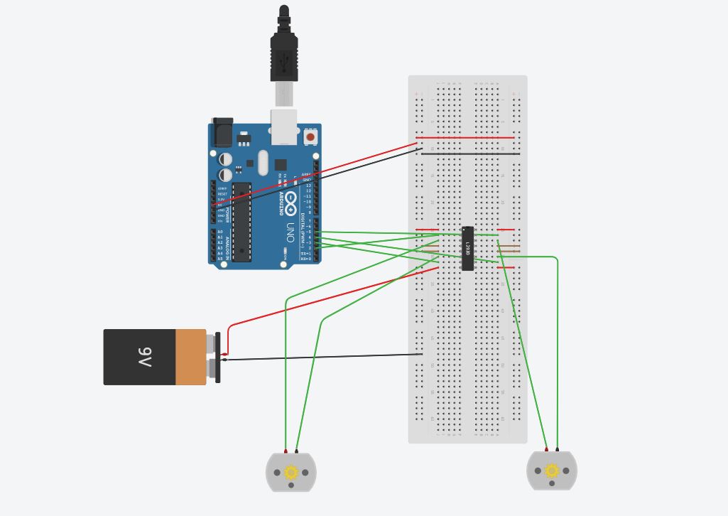
After I got this to work I decided to go to the next step, which was to create a setup that could control 2 motors at once. For this, I found this instructables tutorial which helped me figure out what I would need to get this running. I read through the tutorial, and I found that this setup is different compared to the first one, which only controls one motor, as it uses the L293D Motor Driver IC and an Arduino UNO (which I will later change out with a ATTINY 1614). I went back on TinkerCircuits and I re-made the circuit in the tutorial and uploaded the code to test the setup. Down below is the picture of my setup and the code that was used.
//L293D
//Motor A
const int motorPin1  = 5;  // Pin 14 of L293
const int motorPin2  = 4;  // Pin 10 of L293
//Motor B
const int motorPin3  = 3; // Pin  7 of L293
const int motorPin4  = 2;  // Pin  2 of L293

//This will run only one time.
void setup(){

    //Set pins as outputs
    pinMode(motorPin1, OUTPUT);
    pinMode(motorPin2, OUTPUT);
    pinMode(motorPin3, OUTPUT);
    pinMode(motorPin4, OUTPUT);

    //Motor Control - Motor A: motorPin1,motorpin2 & Motor B: motorpin3,motorpin4
}


void loop(){
  digitalWrite(motorPin1, HIGH);
    digitalWrite(motorPin2, LOW);
    digitalWrite(motorPin3, LOW);
    digitalWrite(motorPin4, LOW);
    delay(2000);
    //This code will turn Motor A counter-clockwise for 2 sec.
    digitalWrite(motorPin1, LOW);
    digitalWrite(motorPin2, HIGH);
    digitalWrite(motorPin3, LOW);
    digitalWrite(motorPin4, LOW);
    delay(2000);

    //This code will turn Motor B clockwise for 2 sec.
    digitalWrite(motorPin1, LOW);
    digitalWrite(motorPin2, LOW);
    digitalWrite(motorPin3, HIGH);
    digitalWrite(motorPin4, LOW);
    delay(2000);
    //This code will turn Motor B counter-clockwise for 2 sec.
    digitalWrite(motorPin1, LOW);
    digitalWrite(motorPin2, LOW);
    digitalWrite(motorPin3, LOW);
    digitalWrite(motorPin4, HIGH);
    delay(2000);

    //And this code will stop motors
    digitalWrite(motorPin1, LOW);
    digitalWrite(motorPin2, LOW);
    digitalWrite(motorPin3, LOW);
    digitalWrite(motorPin4, LOW);

}
Now that I have successfully completed the setup digitally, I will try this with physical materials so I can see physical motors moving. I gathered all of my materials that I needed, and hooked up everything that I needed, and my setup looked like this:
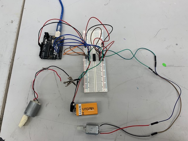
After I got everything ready, I uploaded the code, and the motors spun the way they were supposed to (2 secs clockwise, then 2 seconds counter clockwise for each motor).
The next step for me now is to create a board on EAGLE which will do the same thing that I just completed.
Stage 3 - Creating a motor driver board
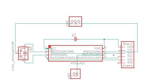
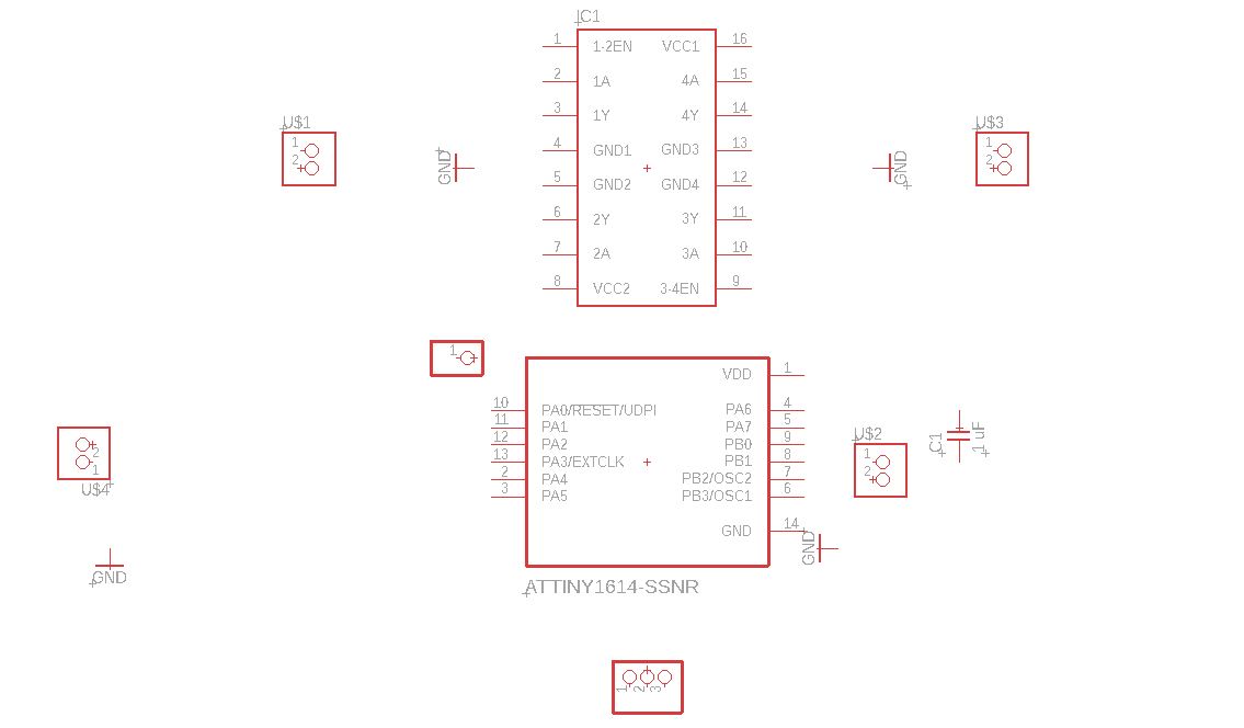
Once I got my experimental setup to work, I got on EAGLE and started designing a board that would replicate the function of the setup I created previously, and would also connect to the ESP32 camera module as well. When I was doing research ahead of time to see how I could make this project wireless and to see how I could integrate a camera, I found the ESP32Camera module, which seemed to be the perfect fit for me. The first step was to get all of my parts onto an EAGLE schematic.
The parts that I needed for this board are the ATTINY 1614 and the L293D motor driver IC. I already had the ATTINY1614 in use on EAGLE already as I was experimenting on EAGLE on my own time, so the one part I did not have was the L293D motor driver board, so I had to find a part library so that I could use the part. I looked up the part for EAGLE and came across a website named SnapEDA, which had the part available to download, which I did, and put it into use so that I could pull it into my schematic. After doing that, I realized that I would want a pad for UPDI programming, 2, an place to plug in power for the motors, a place to plug in power for the 1614 and ESP32Cam, and 3 pads/through holes for the ESP32Cam (VCC, GND, Signal). After putting all of these parts in, here is what my schematic looked like.
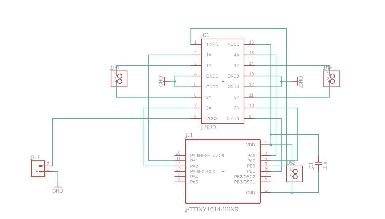
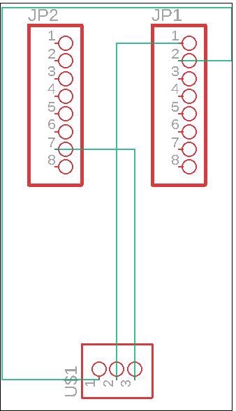
After creating this, I started creating all of the connections that I needed and when I was complete, my schematic looked like this:
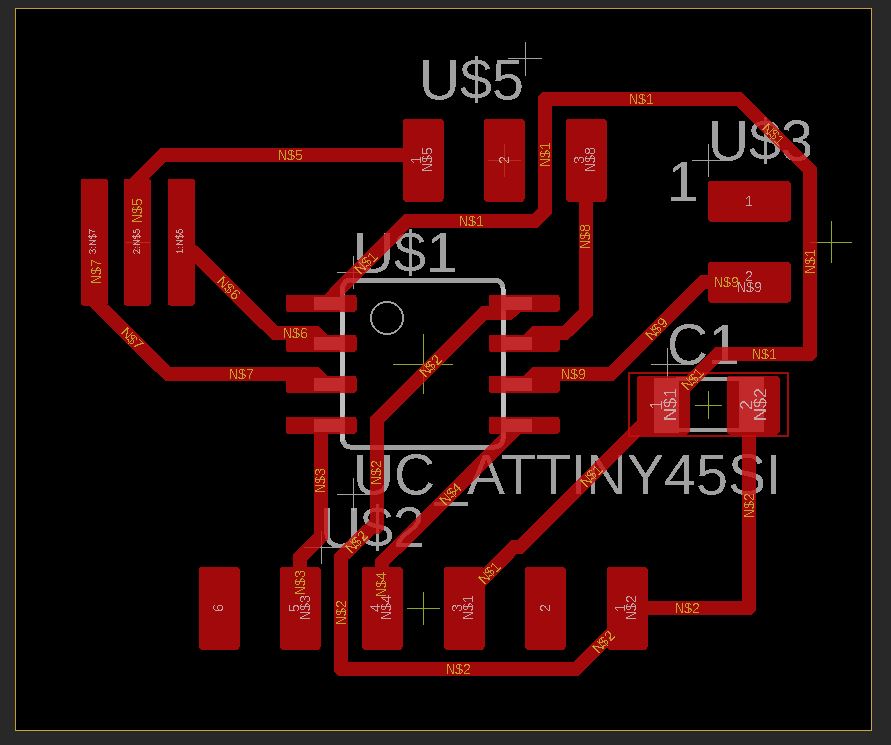
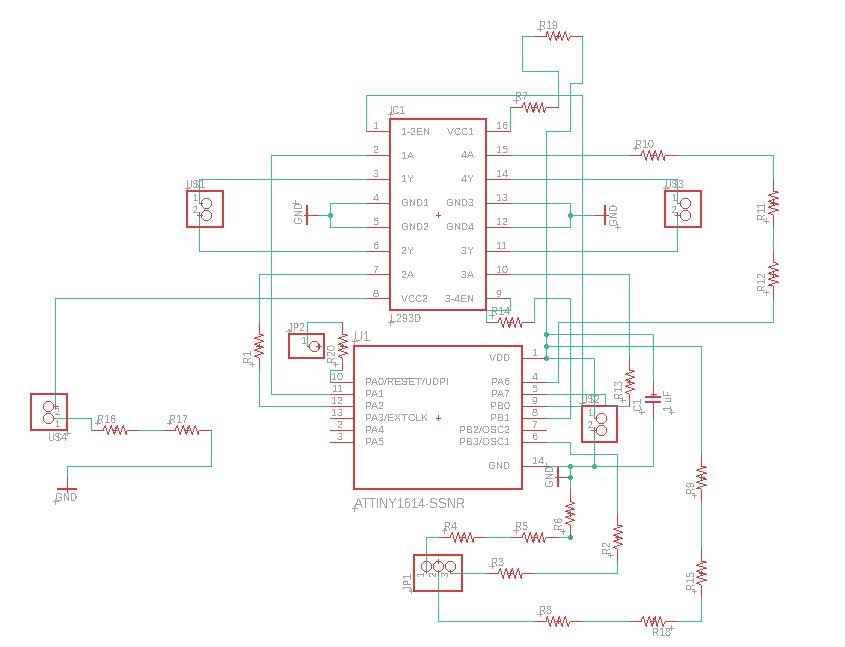
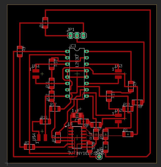
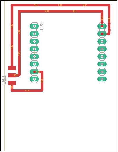
After I did this, I switched over to the BRD and started by applying the 1/64th bit DRC, and then I started creating traces. As I was going along, I realized that I needed jumpers or 0k ohm resistors in order to make all of my connections possible, so I went back to my schematic and added some resistors, and did some trial and error along the way, but I was finally able to get all of my connections made on the BRD file, and the final product looked like this:
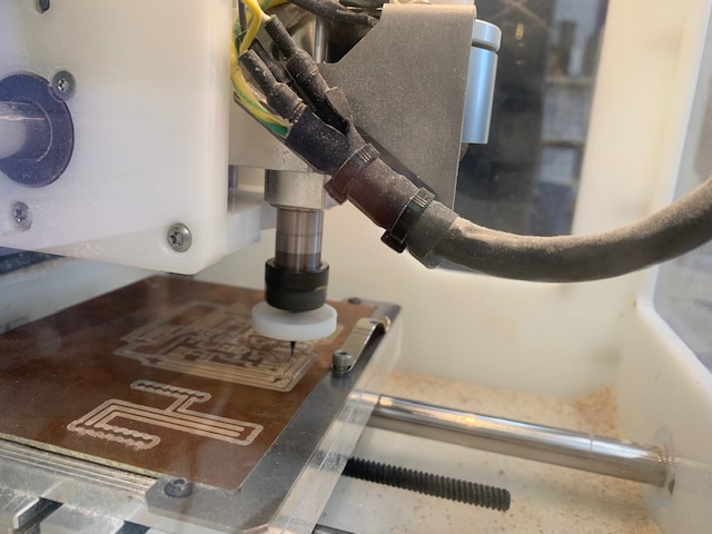
After I was complete, I made sure that there would be no issues with the board, and I proceeded to go mill it out. I put in the settings to use a 1/32 and a 1/64th bit to get the job done, and I started milling
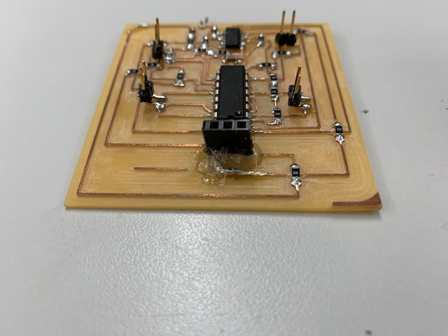
After I was done milling, I got the board out, sanded the board a little bit, and soldered on my components. After I was done stuffing the board, this is what it looked like:
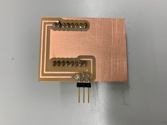
While I was waiting for the main motor control board to mill out, I decided that I would create a board which would have female headers so that the ESP32Cam module could attatch to it, so that board could attatch to the board I am milling out (If that is confusing, there will be pictures further down in the documentation showing this). I went back to EAGLE, and wanted to see if there was anyone who created a ESP32Cam board so that I could just mill it out. I went online, and I found this one website called component search engine which had the ESP32Cam part, but there was a sign-up process, which I ended up doing, but the download kept failing, so I decided to make the board by myself. The first thing that I did was that I looked up a datasheet for the ESP32Cam, as I did not have the part with me at the time, and I looked at the measurements for inbetween the to headers. After I found this number, I simply went to the pinheader part library in EAGLE and I took out the 8-pin header, and placed down two of them. After this, I went back and got a 3 count pad. After I did that, I made the connection from ground, vcc and the signal (GPIO1) to the pads, and here is what the schematic looked like (pretty simple):
After I did this, I switched over to the board view and I spaced out the headers using the information from the data sheet, and then I created the traces, which there were only 3. I then adjusted the size of the frame in order to roughly match the size of the ESP32Cam module, but a bit bigger. Here is what my final board file looked like:
After I was complete with the BRD, I went over to mill the board using the 1/32 inch bit. The process was simple and quick, and after it was done, I sanded it a little bit, and got tweezers to clear the space in between the traces. After that, I soldered on 2-8 pin female headers and 1-3 pin connector. After soldering those components on my board, this is what it looked like:
Now that all of my electronics were complete, it is time to program the 1614 and the ESP32Cam (on its way).
Stage 4 - Programming the motor driver board
Now that my boards were milled and stuffed, it is time for me to create some code that would work to control the motors. The first thing that I will do is to test the code that I previously tested with my breadboard setup. Since I changed up the port selection, I looked up an ATTINY 1614 pinout, and there was a diagram (as shown below) which displayed all of the pinouts and the number I needed to adress them by in the Arduino IDE.
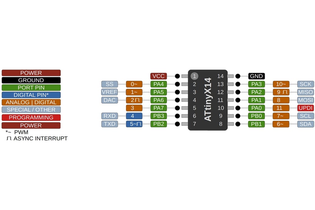
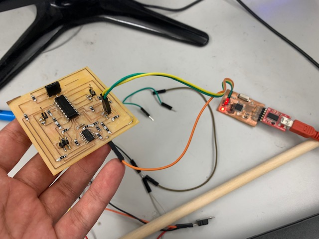
After looking at this, I adjusted my pinouts, and grabbed my UPDI programmer and uploaded the sketch. Once the code was uploaded, my motors spun the way I wanted them to!
Here is the code I used:
//Motor A
const int motorPin1 = 2;
const int motorPin2 = 3;

//Motor B
const int motorPin3 = 9;
const int motorPin4 = 8;

//Enable
const int enableA = 7;
const int enableB = 6;

void setup(){
  pinMode(motorPin1, OUTPUT);
  pinMode(motorPin2, OUTPUT);
  pinMode(motorPin3, OUTPUT);
  pinMode(motorPin4, OUTPUT);
  pinMode(enableA, OUTPUT);
  pinMode(enableB, OUTPUT);
  digitalWrite(enableA, HIGH);
  digitalWrite(enableB, HIGH);
}

void loop(){
  digitalWrite(motorPin1, HIGH);
  digitalWrite(motorPin2, LOW);
  digitalWrite(motorPin3, LOW);
  digitalWrite(motorPin4, LOW);
  delay(2000);

  digitalWrite(motorPin1, LOW);
  digitalWrite(motorPin2, HIGH);
  digitalWrite(motorPin3, LOW);
  digitalWrite(motorPin4, LOW);
  delay(2000);

  digitalWrite(motorPin1, LOW);
  digitalWrite(motorPin2, LOW);
  digitalWrite(motorPin3, HIGH);
  digitalWrite(motorPin4, LOW);
  delay(2000);

  digitalWrite(motorPin1, LOW);
  digitalWrite(motorPin2, LOW);
  digitalWrite(motorPin3, LOW);
  digitalWrite(motorPin4, HIGH);
  delay(2000);
}
Stage 5 - Making the inner and outer wheel
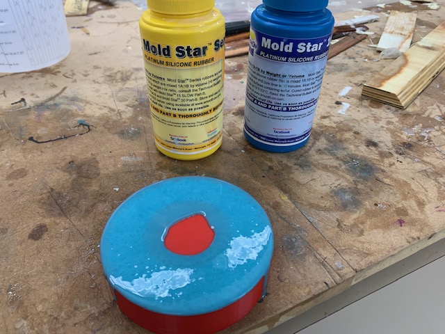
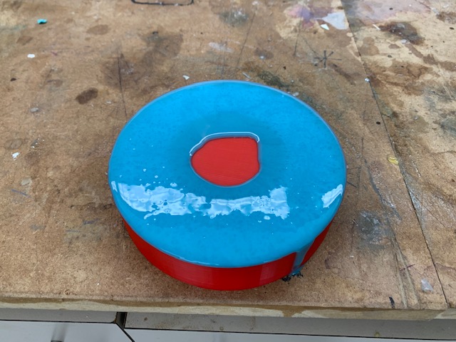
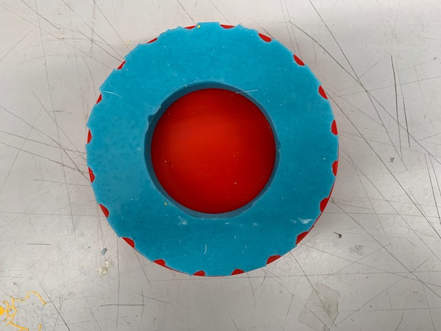
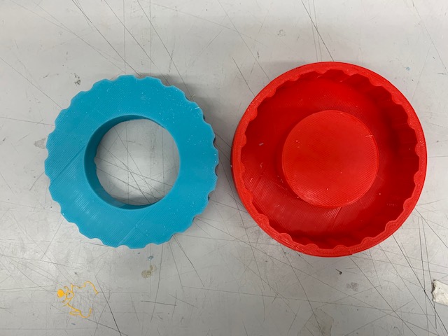
In my Molding and Casting Week, I created a outer wheel for my cast. This cast feels rubbery and it is exactly how I want my wheels to be on the drone, so I will be using the same wheels for the final product. The image below is the wheel I created for my molding and casting week:
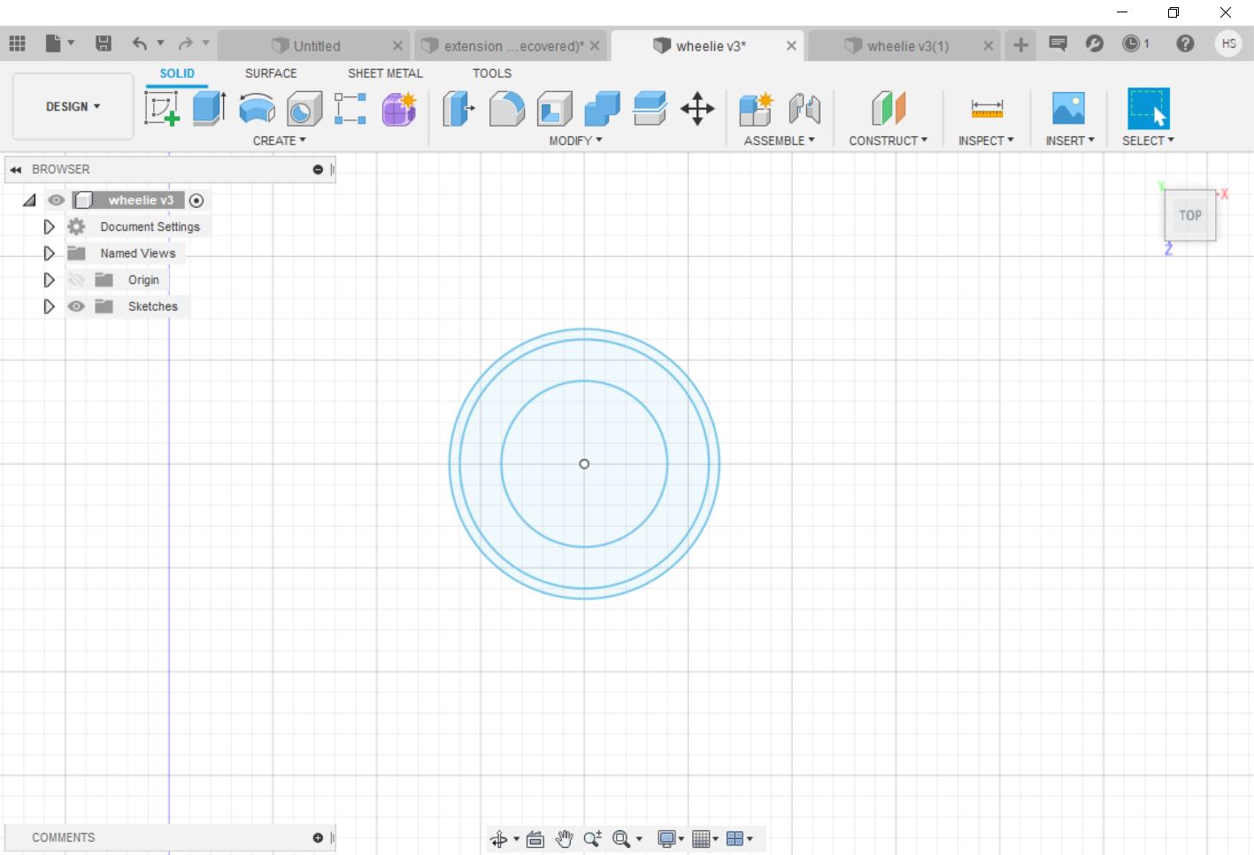
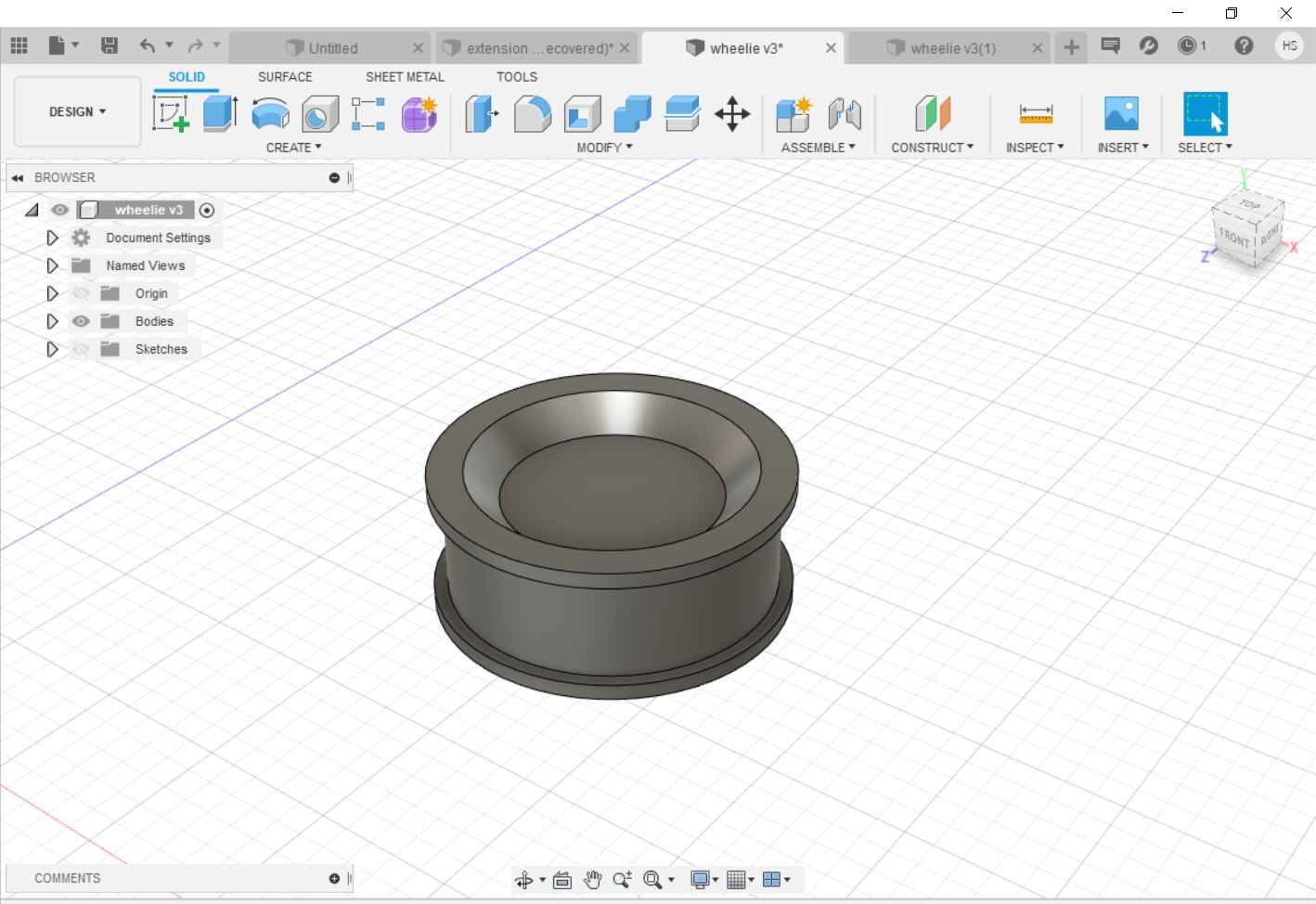
The next step in this process is to create an inner piece that can fit in with the exterior mold. So, I went on Fusion 360, and I started by sketching out the dimensions of the wheel.
After this, I made an extrusion and created a chamfer, which gave me a simple look for the inside of the wheel, which looked like this:
After I was done creating the look, I needed to create a slot in which the axle of the motor can slide into. I grabbed a pair of calipers and measured the size of the axle on the motor, and then added 0.01 cm to the measurements to compensate for the 3D printer. After I did this, I cut into the 3D design, and my inner wheel was complete!
After designing, I exported my file as an STL, and I went over to the 3D printer and printed out my design. Since this was at night, I came back in the next morning, and my inner wheels had turned out really well! Now the next thing that I will have to do is print the body so that can attatch the wheels to it.
Stage 6 - 3D Printing the body and fitting on wheels
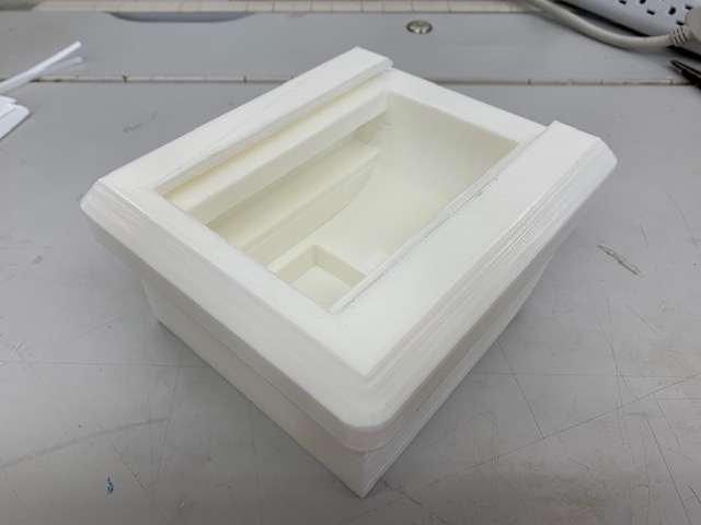
After I was done with my wheel, I decided to create the body of my drone on Fusion 360. I had originally created a design in Week 3 where I created a model of what I wanted my drone to look like. For my final product, I decided that I would modify this design that I had already, and just add a slot where I could slide in an acrylic cover. After making the quick cut in my model, I loaded the stl to check the size of the print and to see how long it would take so that I could make adjustments to the size if needed. I got on Cura and changed the settings to the ones I needed, then I loaded my stl file on. The print was a bit bigger than I expected and the print was also estimated to take around 1 day and 20 hours to complete. I knew that this was not the best way to proceed so I went back to Fusion in order to make my design smaller. I made the design the exact same way that I did the first time around, but I adjusted a couple of things. The first, being the most obvious, is the size of the body, and the second thing that I changed is for my body to have a curved inside. After this, I included little indent on the sides of the body, so that I could drill a hole in the sides later on (I did not know how big the axle was going to be). After I did this, this is what the 3D model of the drone looked like:
After everything was ready, I exported my STL file to the computers connected to the 3D printers. I uploaded my file on cura, and this time, the print was 1 day, which was 20 hours less than last time, so I decided to go for the print. ALthough I designed this drone to be black, I saw that we had white PLA as well, so I decided to print with the white PLA. I thought to try white and if I didn’t like it, I could always spray paint over it with black spray paint. My wheels were also already white so I was already somewhat color coordinated :). After coming in after the weekend, I saw that my print had completed successfully! This is what the print looked like:
The white looked really nice as I thought it would, and I decided to stick with white for my body.
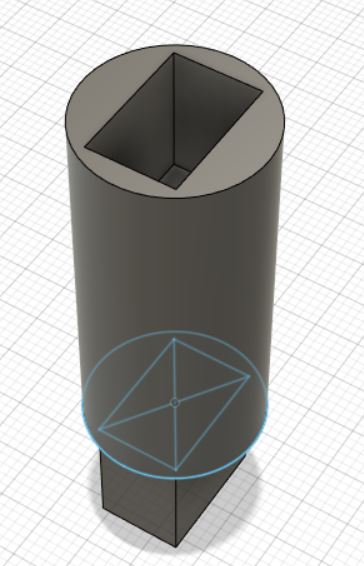
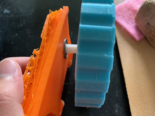
After I created the body, I decided to create the axle extension that I need in order for the wheels to be attatched to the motor while fitting in the body. My idea for how I would complete this is to create a hole big enough for a bearing to fit in case the wheels don’t roll as smoothly as I had planned, but would be able to work without them as well. I measured the size of axle of the gearmotor, and made a quick extension for it using Fusion. The diameter of this shape is not set, but the size I had at this point was the minimum diameter that the extension would have to be. In order to find out what size bearing I would need, I looked for the inner diameter measurements for bearings. After looking for a little bit, I figured out that the 7/8th in. outer diameter bearings would work with the diameter of the extension as the inner diameter of the bearing was very close to the diameter of my extension. Here is what the extension looked like after taking consideration of all of the measurements:
After I was done, I tried fitting the extension on the motor and and the inner wheel, and they both fit perfectly!
Stage 7 - Cutting the Acrylic Cover
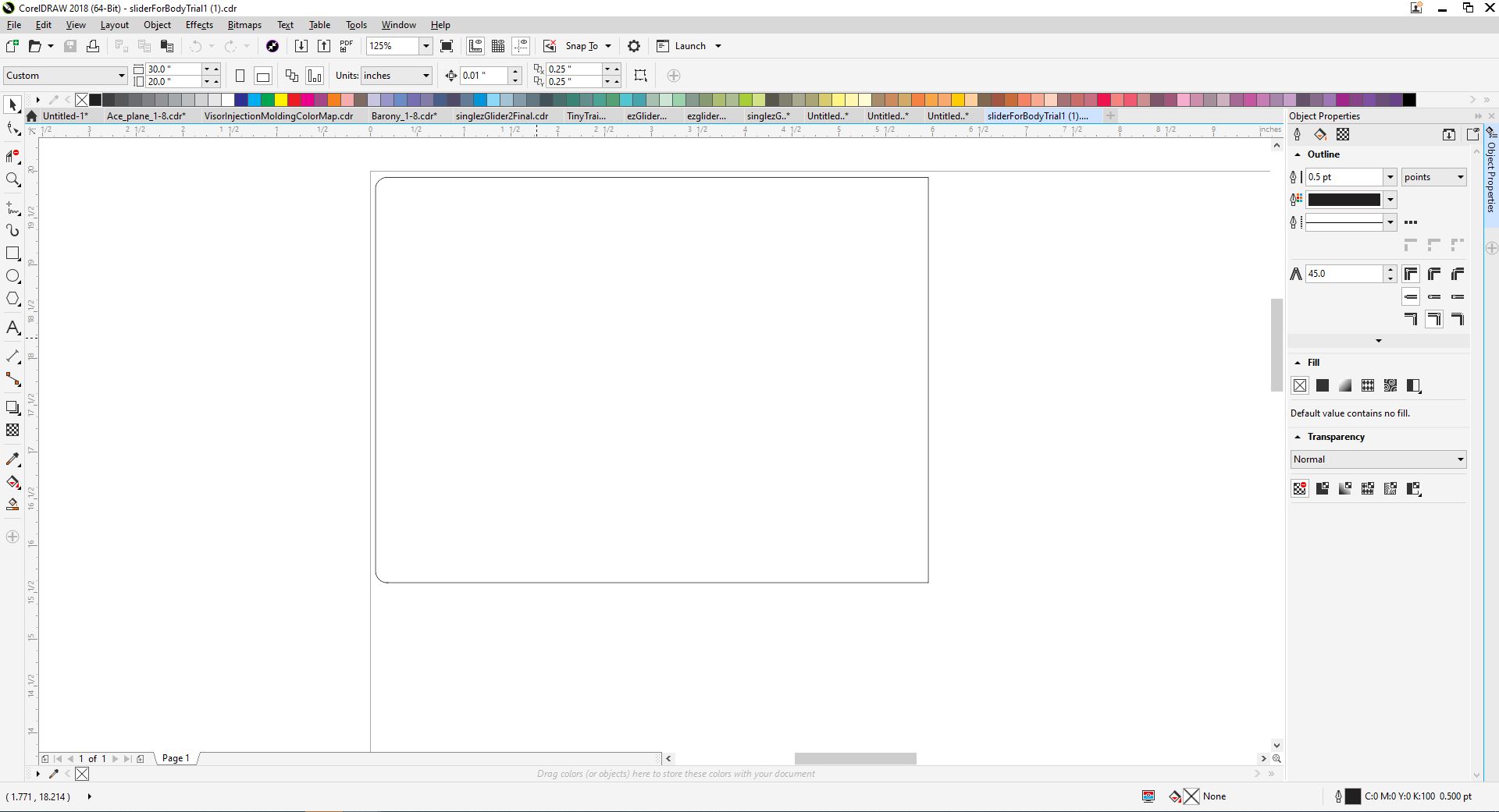
After the body of the drone was complete, I decided that I would create a cover using a grey acrylic so that the insides would be visible, but it is a bit tinted so the look is a bit more stealth. The first thing that I did was that I went back on Fusion and I used the dimension tool in order to find the dimensions of the slot, and once I did that, I went on CorelDraw and I drew up a quick design for the cut. Since I did not want sharp corners on the side I would be touching, I drew two circles in the corner and used the virtual segment delete in order to get rid of the surrounding lines and my final design looked like this:
After I was done, I exported the file as a CDR file and went over to the laser cutter and I got my piece of acrylic and I went to go cut it. To make sure that the laser cutter would go all the way through, I ran the cut twice, and then I went to grab my piece. This is how the cut turned out:
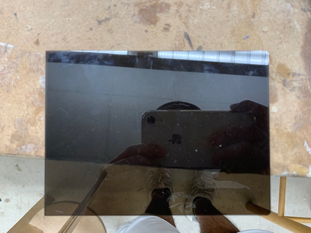
This piece looked nice and fit in my slot nicely and now that I complete with all of the physical components of my drone, I will go back to creating the interface.
Stage 8 - Creating an Interface
In another converstation that I had with Dr. Harris, he gave the idea that I could implement an entire interface onto a website, as Processing is just JavaScript, and that I can use HTML5’s canvas element in order to accomplish this. This was new information for me and it caught my attention, so I decided to do more research on it. After searching for some information, the actual processing.js website had some information about how I could use this feature, and NYU also had a nice page which included an example of how this feature can work. With this, I decided to experiment with this by going on Sublime text, which is a HTML5 text editor, and I decided to try my interface out to see if it would work. The two things I do have to change before I do this is that I have to include the line <script type="text/javascript" src="processing.js"></script> in the head of my document in order to load the processingjs library, and the line <canvas data-processing-sources="myProgram.pde"></canvas> in the body in order to load the canvas tag that would refrence the actual file that I am using
For my interface, I decided that I will implement an interface directly into the HTML code. The way that I plan for this to work is to create code in the HTML that will recognize the letter that is being typed and will send that over to my ESP32, which will communicate that to my ATTINY 1614, and my ATTINY 1614 will have code in which ASCII cases are set up, and once a certain case is triggered, the code for that case will run. Down below is the code that I uploaded to my ATTINY 1614 with all of the ASCII cases:
int curDir = -1; //current direction
int mAe = 8; // input 1
int mAp = 9; // input 2
int mBe = 3; // input 3
int mBp = 2; // input 4
char theDir = ' ';

int enable12 = 7; //enable on left
int enable34 = 6; //enable on right

void setup() {
  Serial.begin(115200); // esp32 communications speed
  pinMode(mAe, OUTPUT);
  pinMode(mAp, OUTPUT);
  pinMode(mBe, OUTPUT);
  pinMode(mBp, OUTPUT);
  pinMode(enable12, OUTPUT);
  pinMode(enable34, OUTPUT);
  digitalWrite(mAe, LOW);
  analogWrite(mAp, 0);
  digitalWrite(mBe, LOW);
  analogWrite(mBp, 0);
  digitalWrite(enable12, HIGH);
  digitalWrite(enable34, HIGH);

}

void loop() {
  if (Serial.available() > 0) { // if a keystroke received from ESP32
    curDir = Serial.read();// read the byte

    switch (curDir) {

      case 48://0 unassigned
        break;
      case 90://z Reverse Left
        digitalWrite(mAe, HIGH);
        analogWrite(mAp, 190);
        digitalWrite(mBe, HIGH);
        analogWrite(mBp, 135);
        break;
      case 83://s Reverse
        digitalWrite(mAe, LOW);
        digitalWrite(mAp, HIGH);
        digitalWrite(mBe, LOW);
        digitalWrite(mBp, HIGH);
        break;
      case 67://c Reverse Right
        digitalWrite(mAe, HIGH);
        analogWrite(mAp, 135);
        digitalWrite(mBe, HIGH);
        analogWrite(mBp, 190);
        break;
      case 65://a Rotate Left
        digitalWrite(mAe, HIGH);
        analogWrite(mAp, 200);
        digitalWrite(mBe, LOW);
        analogWrite(mBp, 55);
        break;
      case 32://space STOP
        digitalWrite(mAe, LOW);
        analogWrite(mAp, 0);
        digitalWrite(mBe, LOW);
        analogWrite(mBp, 0);
        break;
      case 68://d Rotate Right
        digitalWrite(mAe, LOW);
        analogWrite(mAp, 55);
        digitalWrite(mBe, HIGH);
        analogWrite(mBp, 200);
        break;
      case 81://q Forward Left
        digitalWrite(mAe, LOW);
        analogWrite(mAp, 65);
        digitalWrite(mBe, LOW);
        analogWrite(mBp, 120);
        break;
      case 87://w Forward
        digitalWrite(mAe, HIGH);
        analogWrite(mAp, 170);
        digitalWrite(mBe, HIGH);
        analogWrite(mBp, 180);
        break;
      case 69://e Forward Right
        digitalWrite(mAe, LOW);
        analogWrite(mAp, 120);
        digitalWrite(mBe, LOW);
        analogWrite(mBp, 65);
        break;
      default: // STOP
        digitalWrite(mAe, LOW);
        analogWrite(mAp, 0);
        digitalWrite(mBe, LOW);
        analogWrite(mBp, 0);
        break;
    }
  }
}
Stage 9 - Cutting the wires
In another converstation that I had with Dr. Harris, he gave the idea that I could implement an entire interface onto a website, as Processing is just JavaScript, and that I can use HTML5’s canvas element in order to accomplish this. This was new information for me and it caught my attention, so I decided to do more research on it. After searching for some information, the actual processing.js website had some information about how I could use this feature, and NYU also had a nice page which included an example of how this feature can work. With this, I decided to experiment with this by going on Sublime text, which is a HTML5 text editor, and I decided to try my interface out to see if it would work. The two things I do have to change before I do this is that I have to include the line <script type="text/javascript" src="processing.js"></script> in the head of my document in order to load the processingjs library, and the line <canvas data-processing-sources="myProgram.pde"></canvas> in the body in order to load the canvas tag that would refrence the actual file that I am using.
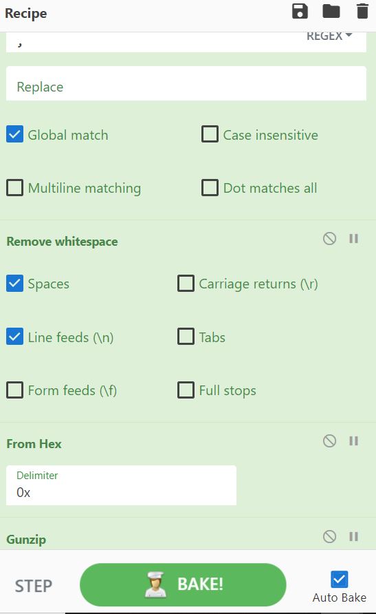
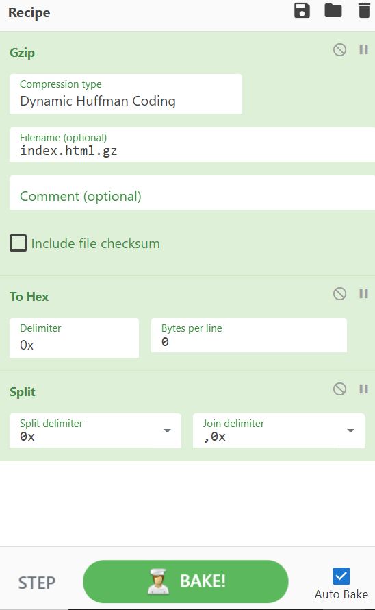
I ended up having to use cyberchef in order to bake. In order to modify the HTML code that was in the example, I had to get the the encrypted text from the Arduino file under “camera_index.h”. After I selected and copied the text, I went over to cyberchef and used the following settings, then pasted the text in, which gave me the HTML code for the website.
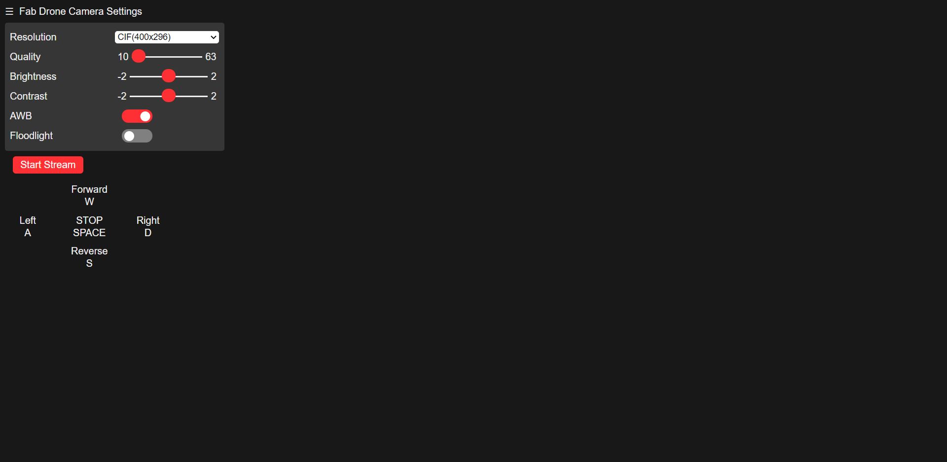
After I got this to work, I copied and pasted all of the HTML code into sublime text, which is an HTML text editor. After I did this, I proceeed to paste the interface that I created earlier into the code, and here is how the page turned out:
After this was complete, I had to turn the html back into the hex array and I did this with cyber chef as well, and these are the settings that I used:
After I was done with this step, I had to test out the interface to see if it could control the motors or not, so I uploaded the code to my esp32, and went on my computer in order to open the website by typing in the IP address of the ESP32 cam. Once I did this, the page successfully showed up, and here is a video of me spinning the motors using the web interface:
Stage 10 - Configuring ESP32 Camera Module to work on body
In order for the ESP32Cam to work on the body, it must be connected to the internet and a power source (5v). I would also need to create some sort of opening on the body so that the camera can see infront and also for the light on the ESP32cam to be able to shine. This was due to me not being sure of the sizes/ fit of the ESP32cam board extension. I decided to fit in the board without the ESP32Cam extension so that I could mark up the areas that I would have to remove. After everything was marked up, I grabbed a chisel, and started chiseling away. After a couple of hits, the general shape was formed, and I grabbed a couple of files, and filed away the rest of the way. I would stop every five minutes or so in order to see whether the ESP would fit, and after about an hour, I finally go the ESP32 cam to fit perfectly on the front. After this was complete, I was able to provide power to the ESP32cam using my computer and I entered the IP address of the ESP32cam and the website showed up, so now the next step for me to complete is to have a power source that can fit in the drone so that this project can be wireless.
Stage 11 - Getting a power source
Now that I am going wireless, I cannot supply power from my computer, but will rather need a power supply. In my tests, I powered the motors using a 6v battery pack (consists of 4, 1.5v double AA batteries), and I used my computer to power the ATTINY 1614, but now I will use a 9v power supply regulated down to 5v using the L780SCV 5V regulator. Before I used the battery, I grabbed a multimeter and checked the voltage to make sure that I had a fully charged battery, and the multimeter read a little over 9v, so I was ready to go. I wired the 9v battery to the regulator, which I attatched to my board. Once everything was powered up, I opened my computer and typed in the IP adress of the ESP32cam module, and within seconds, the interface popped up! I made sure that everything worked like earlier, and once that I done, I decided to unplug the battery and just repeat the process one more time. Although I thought that everything would work fine, once I tried running everything for the second time, I was unable to get the website to show up. I was initially not sure about what could cause the problem, but I figured that the battery was already drained, so I took it out and measured the voltage again with the multimeter and it was only outputting 7.4v, which was not enough. I also decided to do a bit more research on the ESP32cam, and I found out that it requires a lot of current to work, so I decided that it would be best if I switched over to a lithium polymer battery. I ended up finding two, so I will also be changing out my 6v battery pack as well. I found one 850mAh battery and one 800mAh battery in the lab, so I decided to use the 850mAh battery to power the ESP32cam and the ATTINY 1614, and the 800mAh battery to power the motors. I also discussed this decision with Mr. Rudolph, an engineering teacher at my school and a Fab Academy graduate as well, and he pointed me towards a new buck converter, which was the LM2596, which was a bit different because it can step down different amounts of voltages (up to 40v), which can be adjusted by the petentiometer which was on it. I got the battery and connected it to the “in” side of the converter, and placed the multimeter on the “out” side of the convereter and measured the voltage. While I was doing this, I turned the petentiometer and did this until the voltage on the multimeter read a little over 5v. Once this was complete, I also found a button/ switch which could turn the power on or off, so I soldered it to the power side of the battery and connected the other side of the button to the converter itself. After this was complete, I soldered on the rest of the connections, and I was ready to go! I went to rest everything once again, and after testing this setup for about three times, everything was working perfectly, so I set everything inside the body of the drone.
Stage 12 - Test Drone
Now that everything is completely assembled, I will try to use this drone like a final product. Everything other than the 9V regulated down to 5v power supply is hooked up, and in order to start up my drone, I will plug in the VCC cable from the battery to the board. Once I compelete this, I will go to the IP adress on the website. The ESP32Cam module takes a couple of seconds to boot up, but once the sequence is complete, the website should pull up, and everything is set to go.
Here is a video of the test I did and the drone worked!!!
Materials
Here is a table of all the parts that I will be using (Includes what I plan on using and will be updated)
| Qty | Description | Price | Link | Notes |
|---|---|---|---|---|
| 1 | PCB Boards | $4.00 | In Lab | |
| 1 | ATTINY 1614 | $0.71 | MicroChip | In Lab |
| 20 | Pin Headers | $0.97 | Digikey | In Lab |
| 1 | Wires | $9.99 | Amazon | In Lab |
| 2 | ESP32 Cam Module | $18.99 | Amazon | |
| 2 | L293D Motor IC | $1.75 | DigiKey | In Lab |
| 3 | Grey 1/8” Acrylic | $26.99 | estreetplastics | In Lab |
| 2 | DC Motors | $2.95 | Adafruit | In Lab |
| 1 | Buck Converter | $1.50 | Amazon | In Lab |