3. Computer Aided design
Assignment
This week, the assignment was to explore in 2D and 3D model software and to make a possible model of what your final project would look like.
Beginning
I started this week by deciding which CAD software I will be using. After researching for a while, I came to the conclusion that I would use Fusion 360, as I had some experience with it, CorelDraw, as it had an interesting and simple UI, and Free CAD, as it was free and available for me to use.
Fusion 360
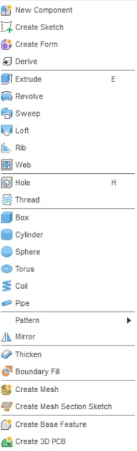
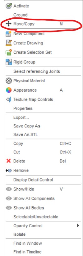
I started this week by using Fusion 360 to model my Twitch drone. Down below is an image of the menu of things that you could create or modify in Fusion 360.

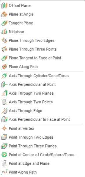
With this, there are different menu options for each different function that you click on. For example, if I click on create a sketch, a new menu will appear like the one below.
Now that I am in the sketch menu, I will create a line, approximate to the ones I originally had my sketch in. The base of the drone will be 22.5cm x 20.5cm, and I will use the line tool to make the lines in this sketch.

Once I have completed the rectangle, I extruded it so it looked like a box
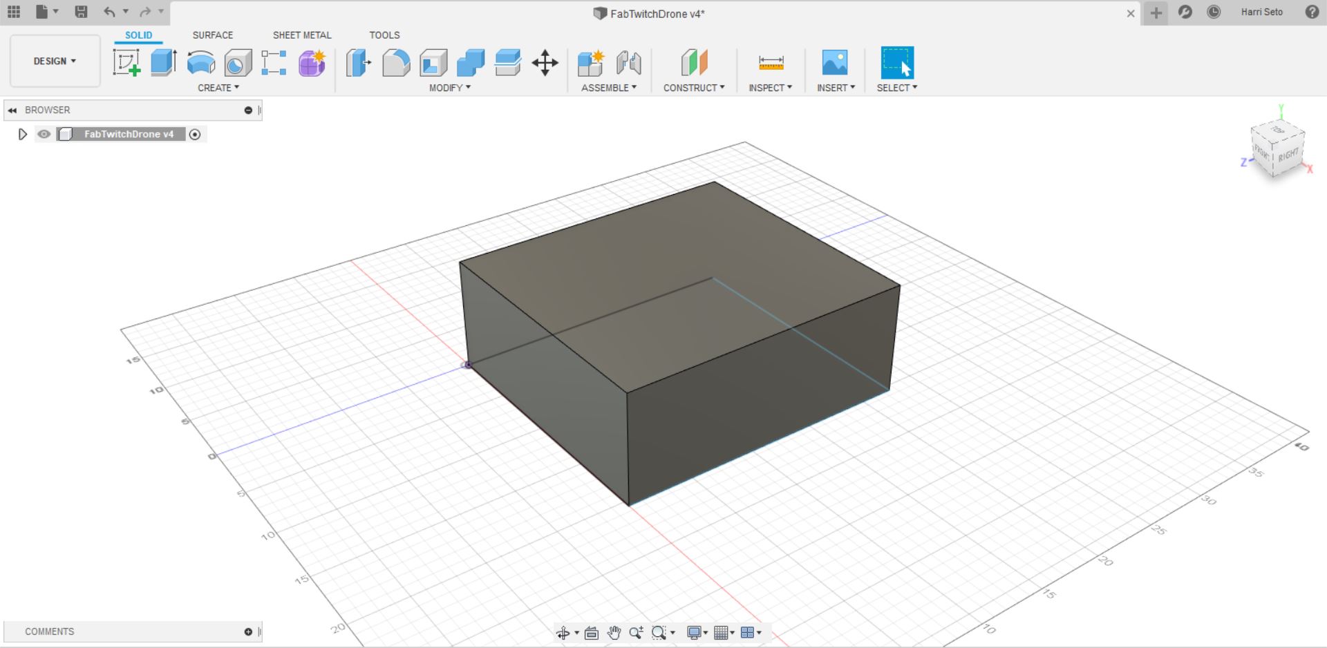
Once I did that, I created individual sketches on each of the 4 faces of the box towards the top, and then I extruded them so there would be an overhang on the box.
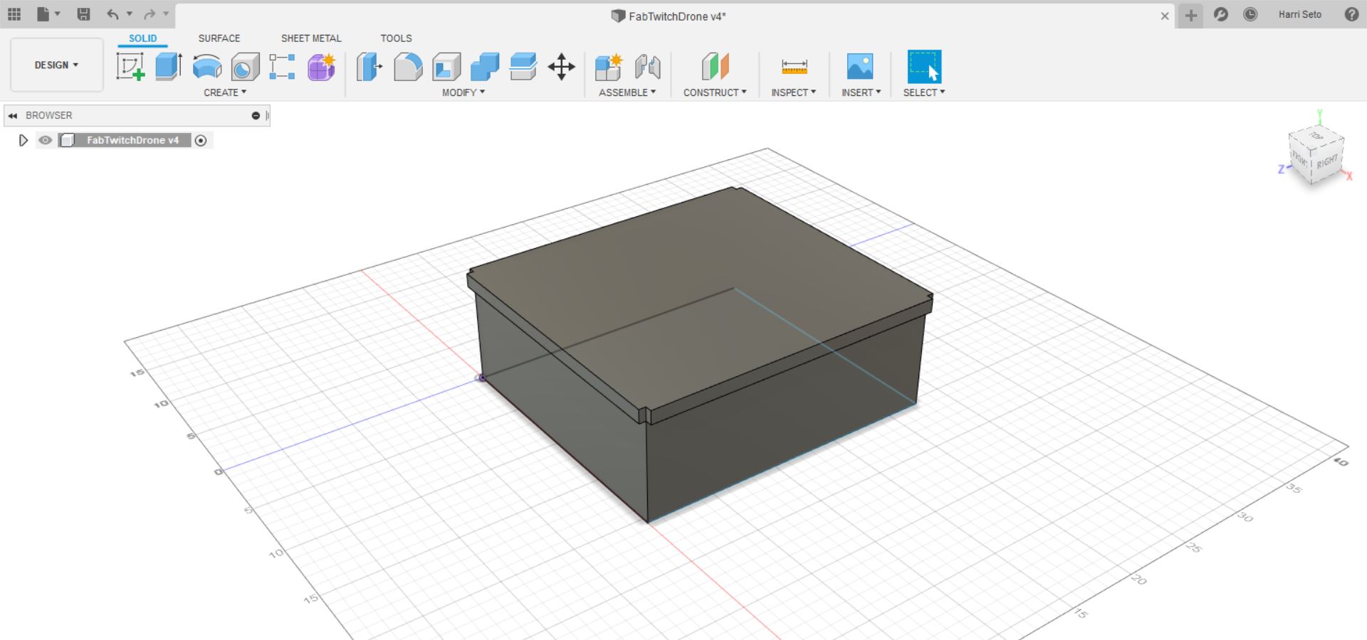
After that, I fileted the corners and made a top piece and extruded it and fileted it.
Then, I proceeded to make two circle sketches on the sides of my drone so that my wheels would be able to slide on to them in an assembly. After the circles were sketched, I extruded them.
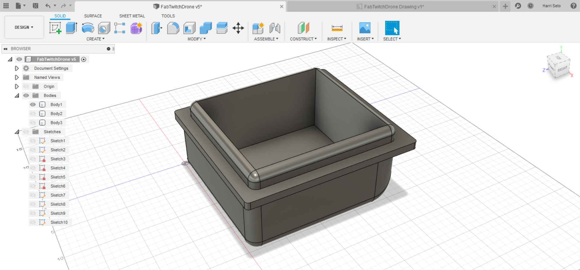
After this was complete, I decided to cut from the top to the bottom from the top piece that was on my drone as seen below.
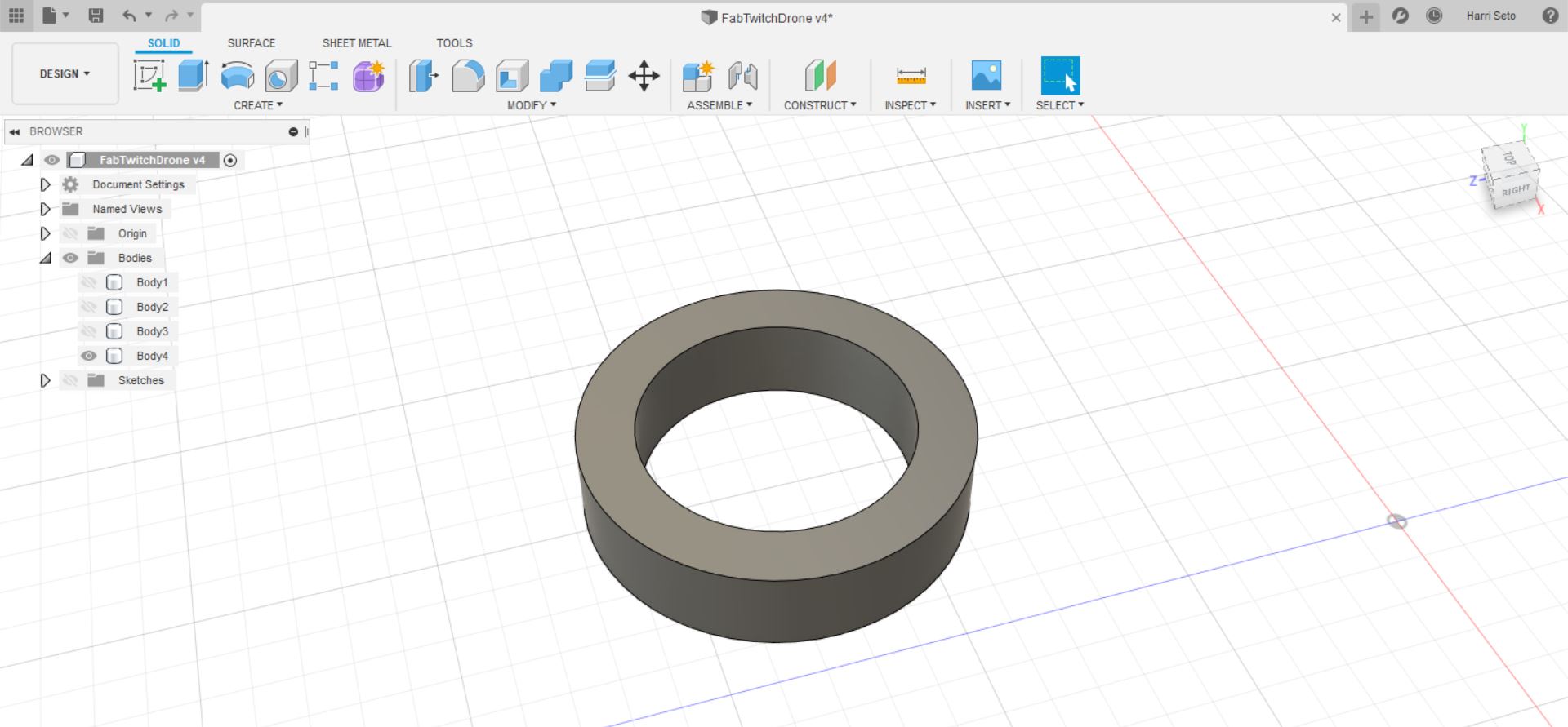
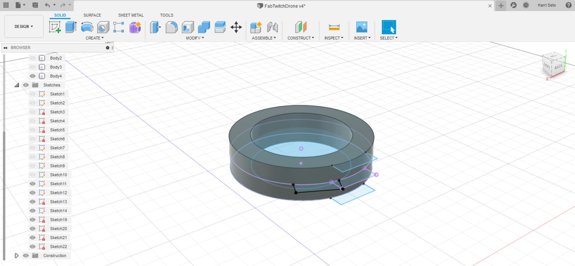
Once I finished the main body, it was time for what I thought was the hardest part of the project, being the wheels. I started off with a sketch of two concentric circles, like a donut, and then I extruded them. I also made sure that the inner circle’s diameter matched one of the circles on the side of my drone.
Once I did this, I made two sketches on the top and bottom like a three-sided rectangle connected to the curve and created a midplane between.
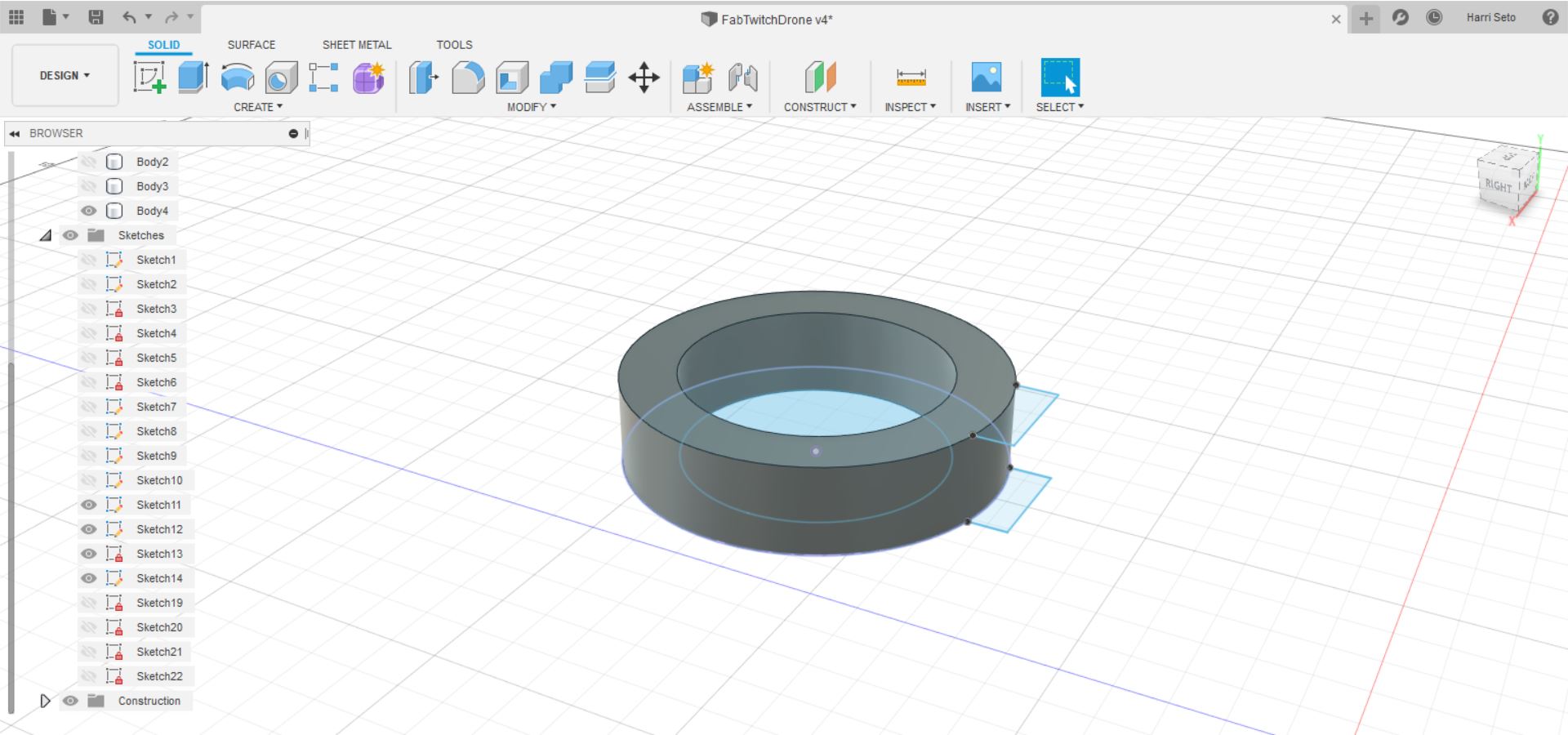
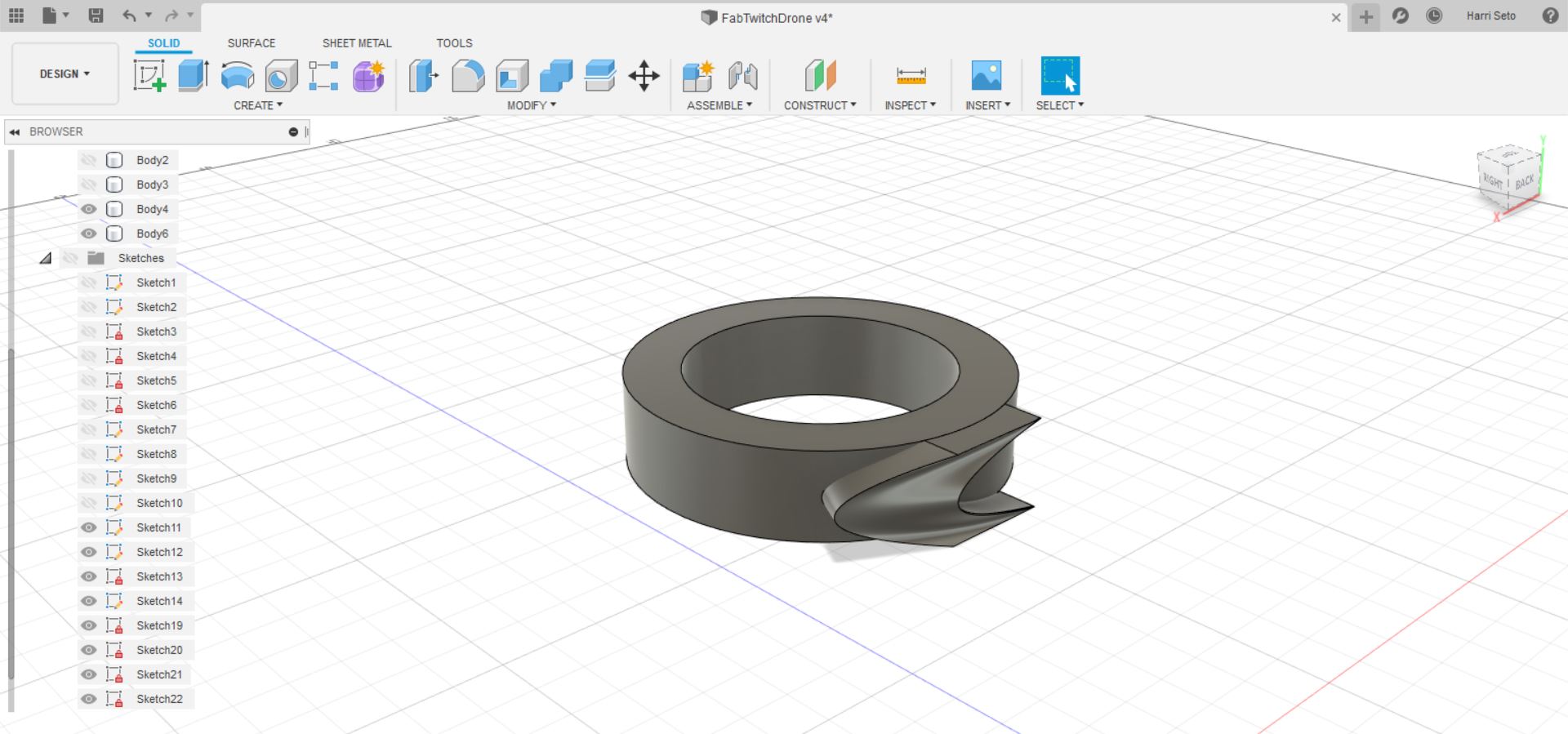
After I did this, I translated the same sketch onto the midplane, and then I created a circular pattern, on the angle mode, and I turned one of the sketches 232 degrees.
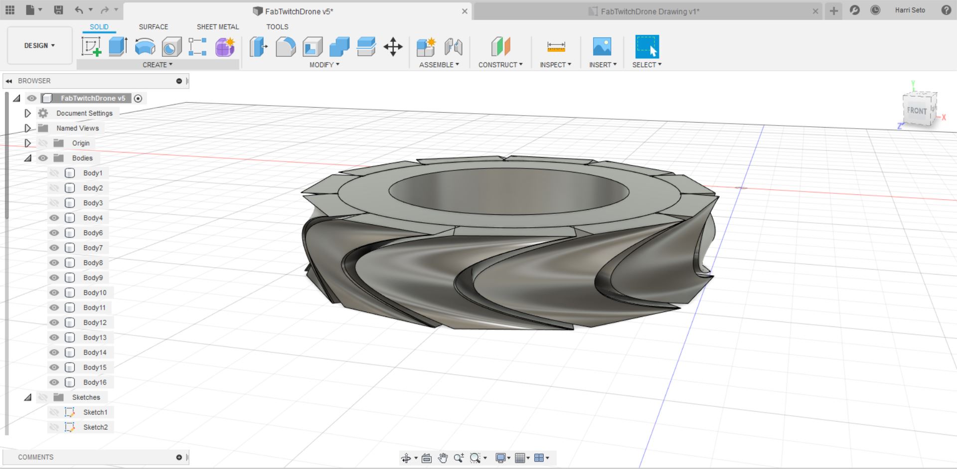
Once the sketches were lined up, I made a loft connecting the sketches together. I would then make a circular pattern with this body, and make it so the wheel has treads to it. The wheel looks like down below:
After this was complete, I learned about what I thought was the coolest part of the build, which was the assembly. In the assembly, I was able to get the wheel to go onto the circles that I had extruded earlier, and they could have a spinning effect to them. In order to do this, I had to convert the bodies into components and then had to choose the option under assembly which said joint.
Once I selected this, I was able to select the component I wanted and then in a swift animation, the wheel was on the side. To get the other wheel on the other side, I just copied and pasted a wheel, which made a new component and repeated the process.
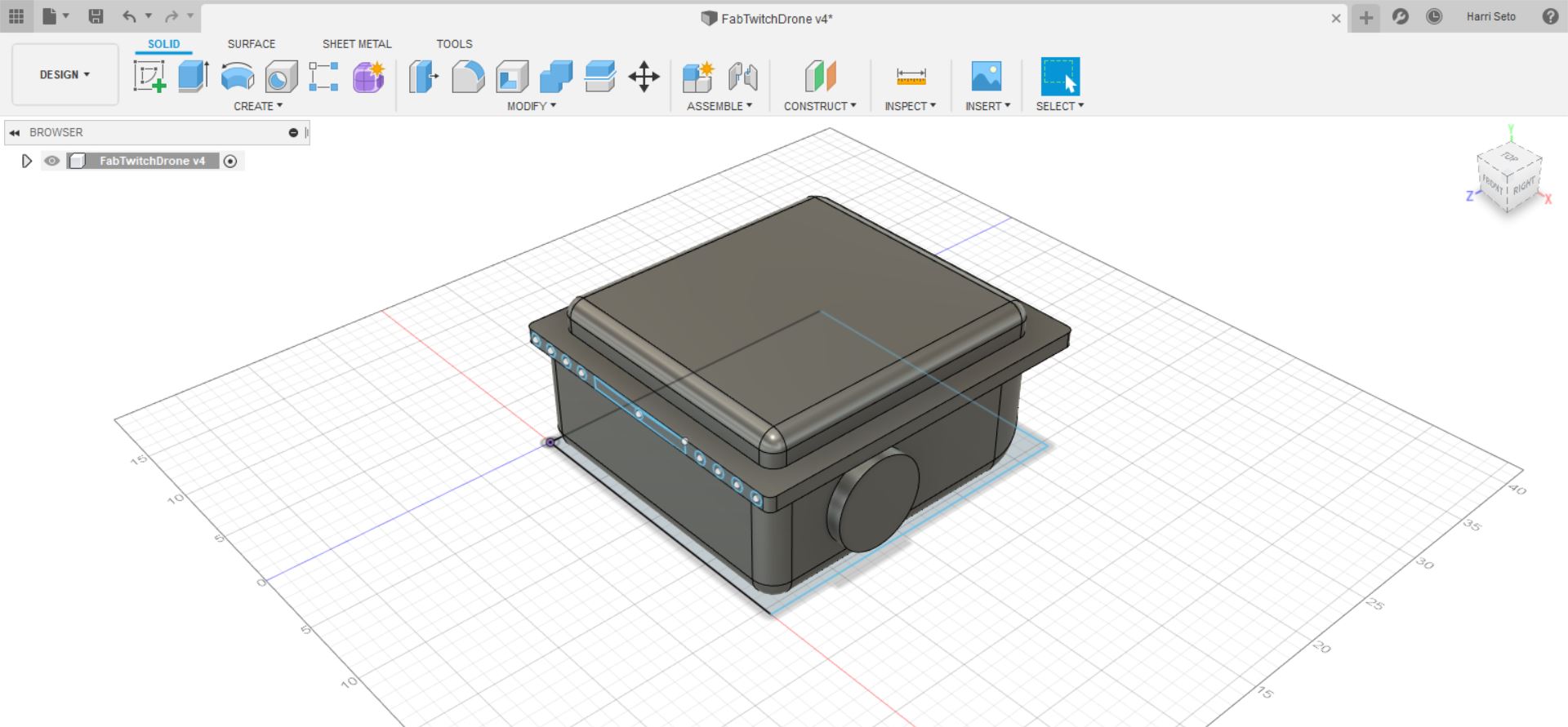
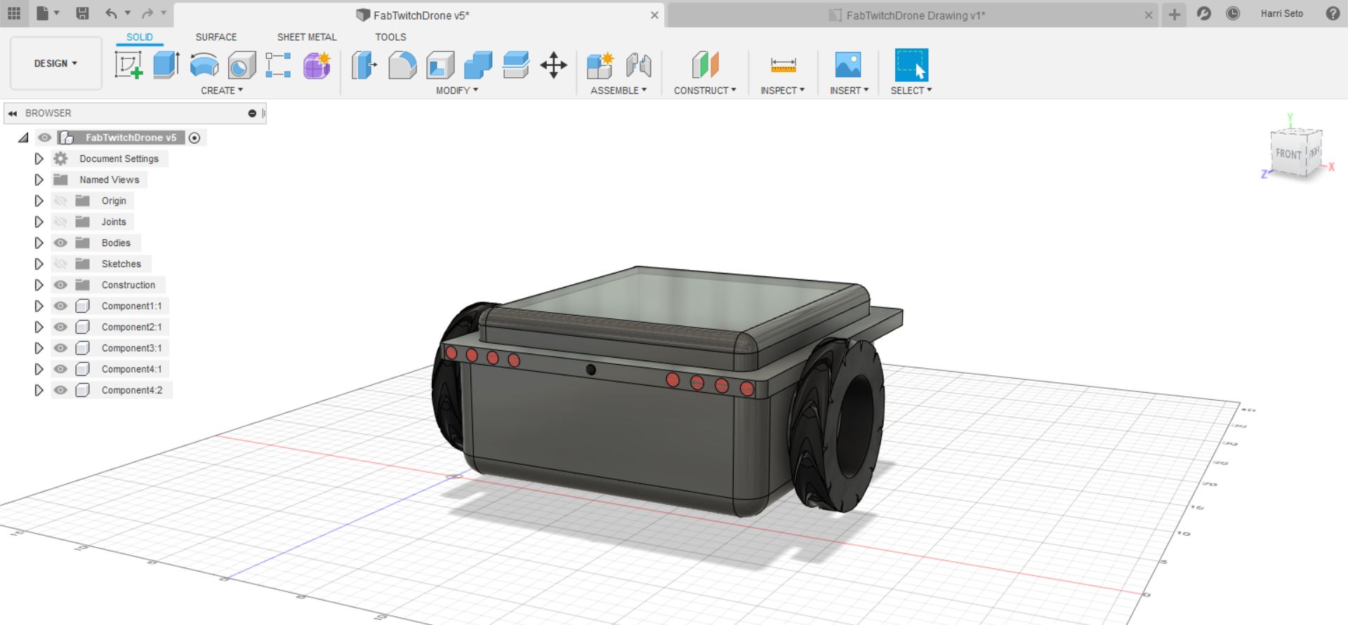
For the final touch to this 3D model, I added appearances to each part of my drone, which helped the touch of reality to come into the model. I started with the main body of the drone, in which I placed a metallic look, and for the wheels, which I placed a rubber look. I also made 4 circles on each side of the front of the drone and added the red LED appearance on those parts. I also made a sphere in the middle, representing where the camera would go on the drone. In addition, I also made an extrusion at the top of my opening, which I gave a glass appearance. The final product is shown below.
Drawing in Fusion 360
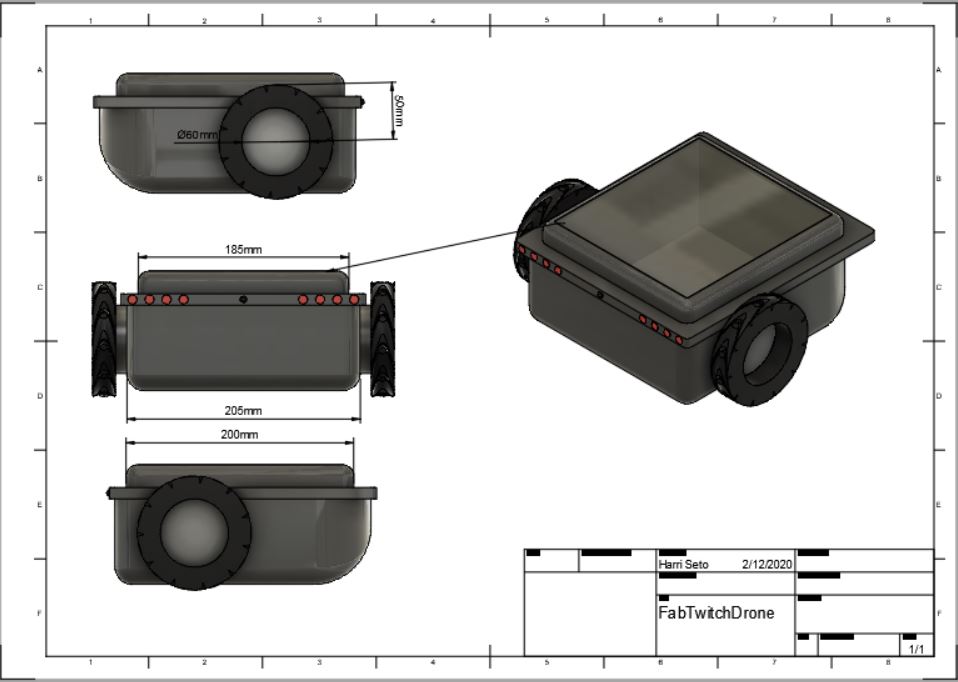
One cool thing that I found out while working with Fusion 360 was the Drawing mode. I was able to get my whole boy into the drawing mode once, and then I was able to adjeust the angle in any direction I desired. Another thing I learned while using this mode was the dimension tool which would give me the actual measurements of what I drew, although the image itself was scaled down by 1:2. Down below is an image of what the final product looked like.
CorelDraw
This week I also got to use more of CorelDraw, which I already have a lot of experience with, making things such as files for a laser cutting machine, and for vinyl cutting, and I was excited to continue using CorelDraw. Down below is the menu in Corel in which all the tools are located

I used many tools in order to make designs but some of the most important in my opinion other than the basic drawing tools were the two mirroring functions, which you can mirror anything that you select, either horizontally or vertically.

Another cool tool that is important for a lot of designs is the virtual segment delete. This tool is accessed by holding on the crop button and then dragging your mouse to where it says virtual segment delete. This tool can delete individual segments in a sketch that you have and is useful if you ever need to cut small segments that are in a design that you don’t like, or in order to cut lines that overhang in a design.
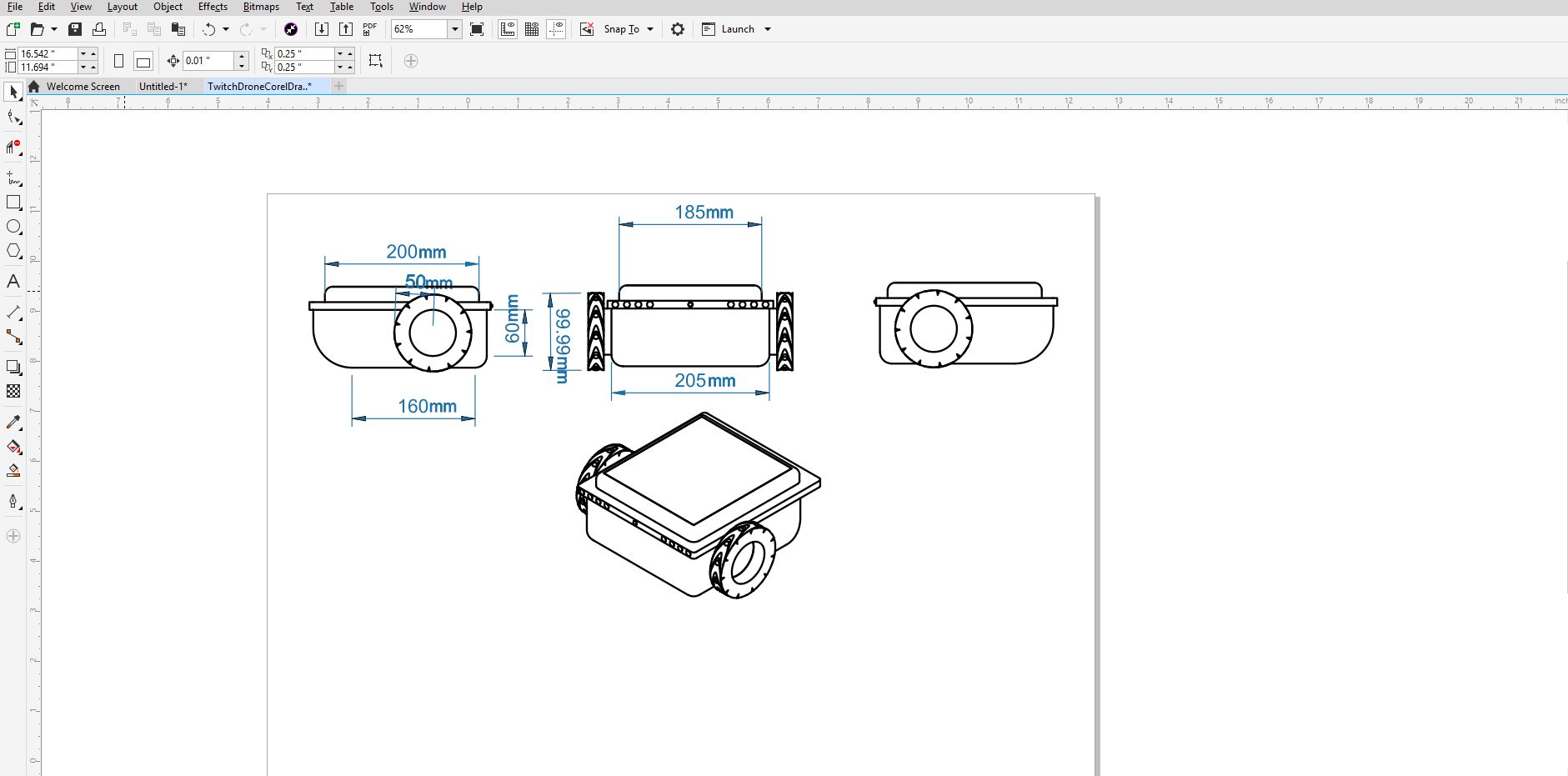
In Corel, I tried something different this time, as I decided that I would take the Fusion 360 file and then import it into CorelDraw. I went to export the file as a pdf, and then I was able to open that file in CorelDraw. Once I did, I redid the measurements and labeled them again, and I also tweaked a few things in the design to make it look better. The final looked like below.
Summary
This week was cool as it brought the concepts from a sketch to an actual rendering that people can look at. I learned some cool things this week such as assemblies, which were very helpful in my project and I hope that as I continue, I will learn some more cool tricks and will be able to get the rendering completed faster while maintaining quality.
Files
Here are all my files from this week. Click Me