8. Computer controlled machining
Introduction
This week, we had two assignments, with one being a group assignment and the other being an individual assignment. The group assignment for this week was to test runout, alignment, speeds, feeds, and toolpaths for our machine. The individual assignment for this week was to make something big, which includes designing, milling, and assembling the item. NOTICE This week may be affected slightly due to the spread of COVID-19 in the area.
Group assignment
This week our group decided to work on the group assignment first. It was a good way to get to know our machine, as we are able to test our machine before we made our individual cuts. The link to the group assignment can be found here.
Individual Assignment
This week, our individual assignment was to create something big on the CNC machine. The first thing I did was that I brainstormed for a while of what would be interesting to make big. Then, I decided to look at previous years and other inspirations of what to make. I finally came upon an image of a UFO and thought that it would be cool to make a big UFO and design it so that it would look like it is floating.
The first thing I did was that I created a sketch of what I wanted my UFO to look like, and this is what the sketch looks like
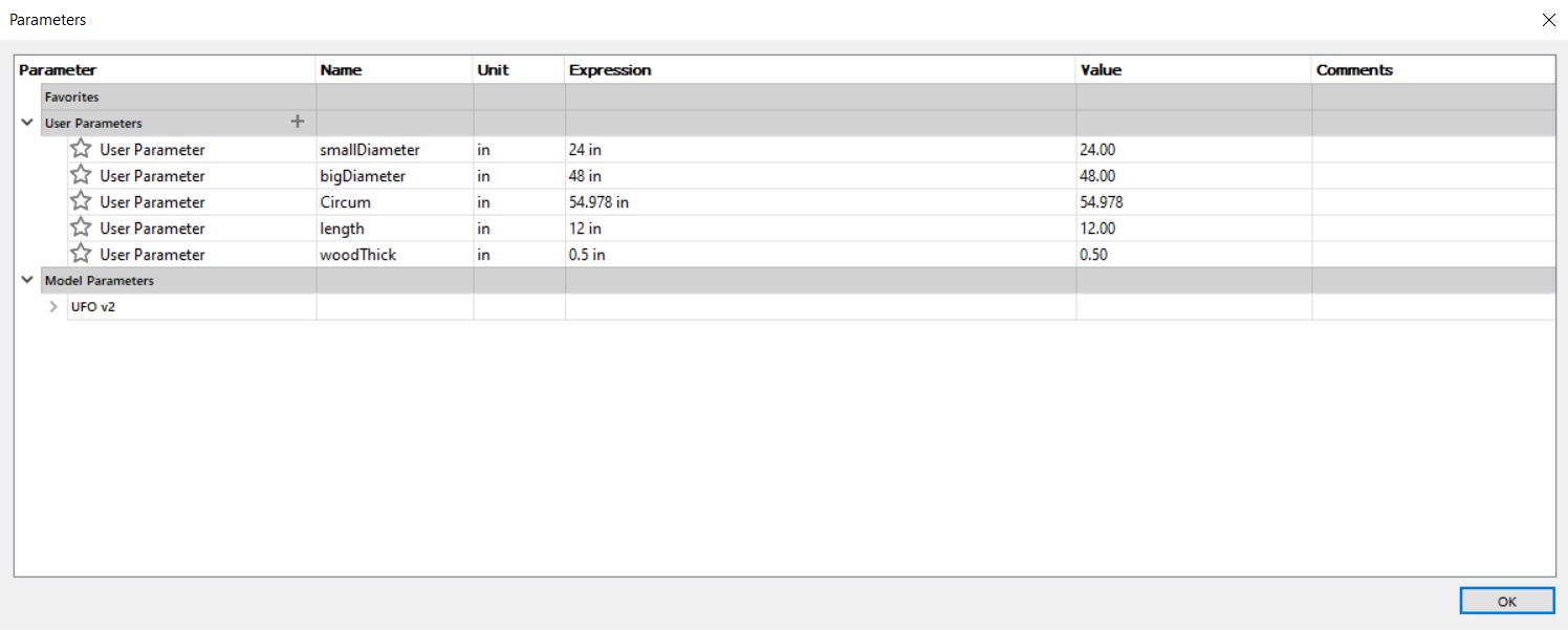
After making a quick sketch, I headed over to Fusion 360 to start my actual design. The first thing I did was that I figured out the measurements for my design, and then I inputted them in my parameters. Here are the parameters that I used for my design.
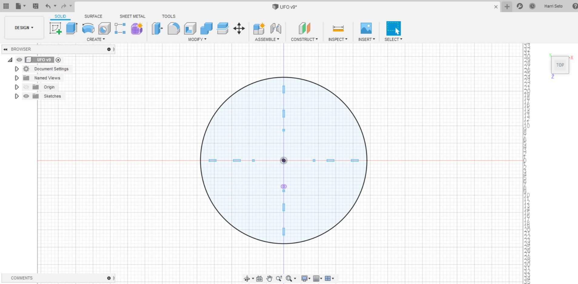
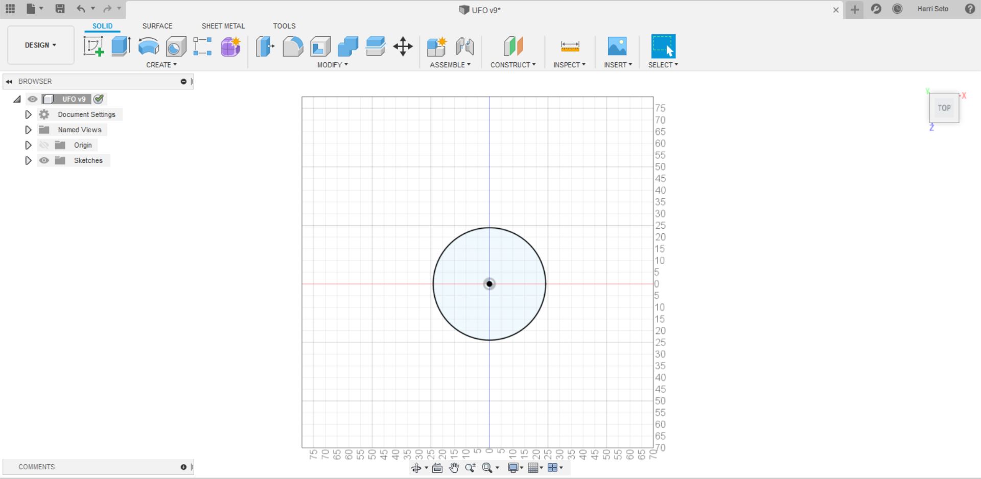
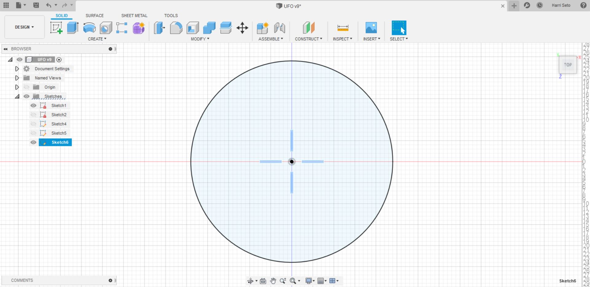
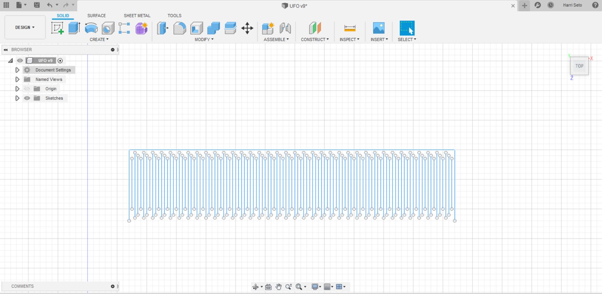
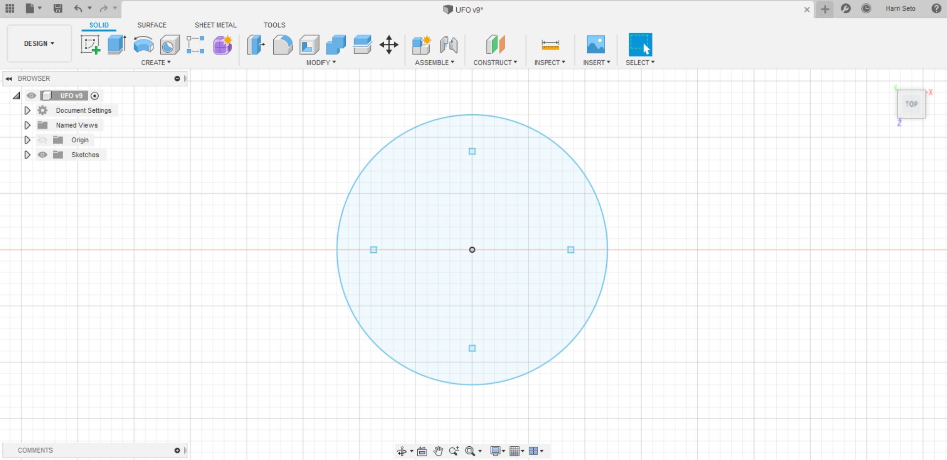
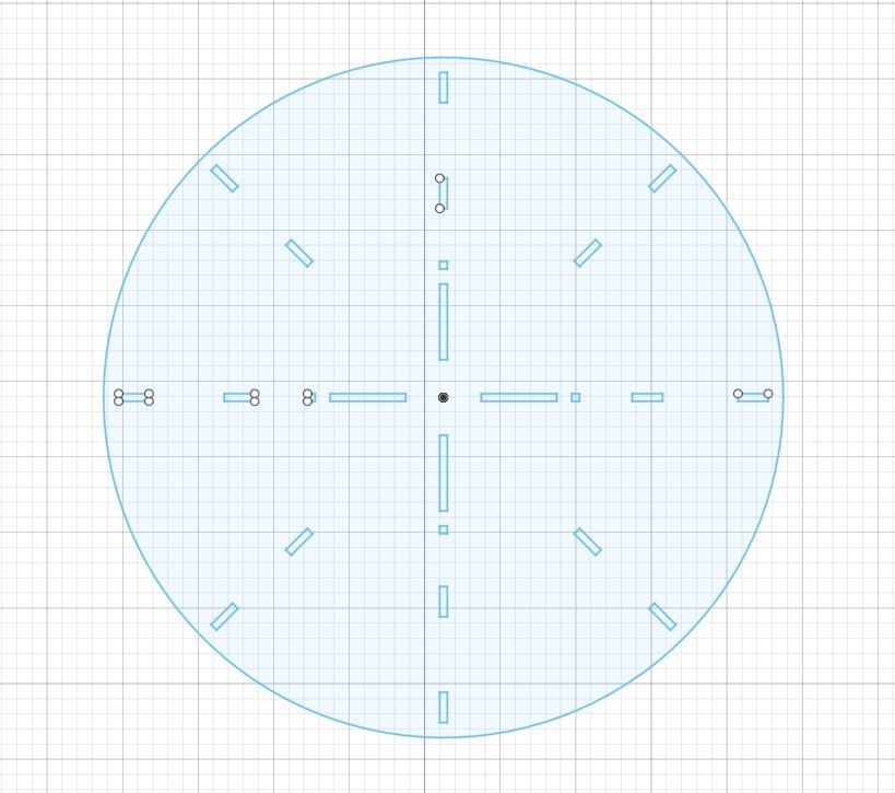
After I configured my parameters, I decided that I would start with the living hinge aspect of my cut, as it would be the most crucial part of the ufo, as it had to curve and press-fit in multiple areas around the base. There were two parts including the living hinge, with one being the cylinder holding the center of my design and the other being the part that wraps around the top. I believe that wrap-around will be the most difficult part of the design, and I believe I will spend most of my time here. Down below is the first step I took to make the UFO, which was designing the base on which my whole structure will rely on
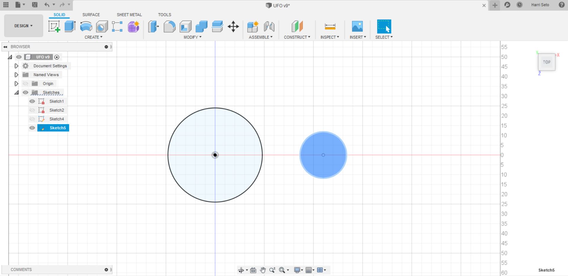
After I had got the sketch to work, I designed the cylinder/ center piece for my UFO, which relies heavily on the living hinge bending into a circle.
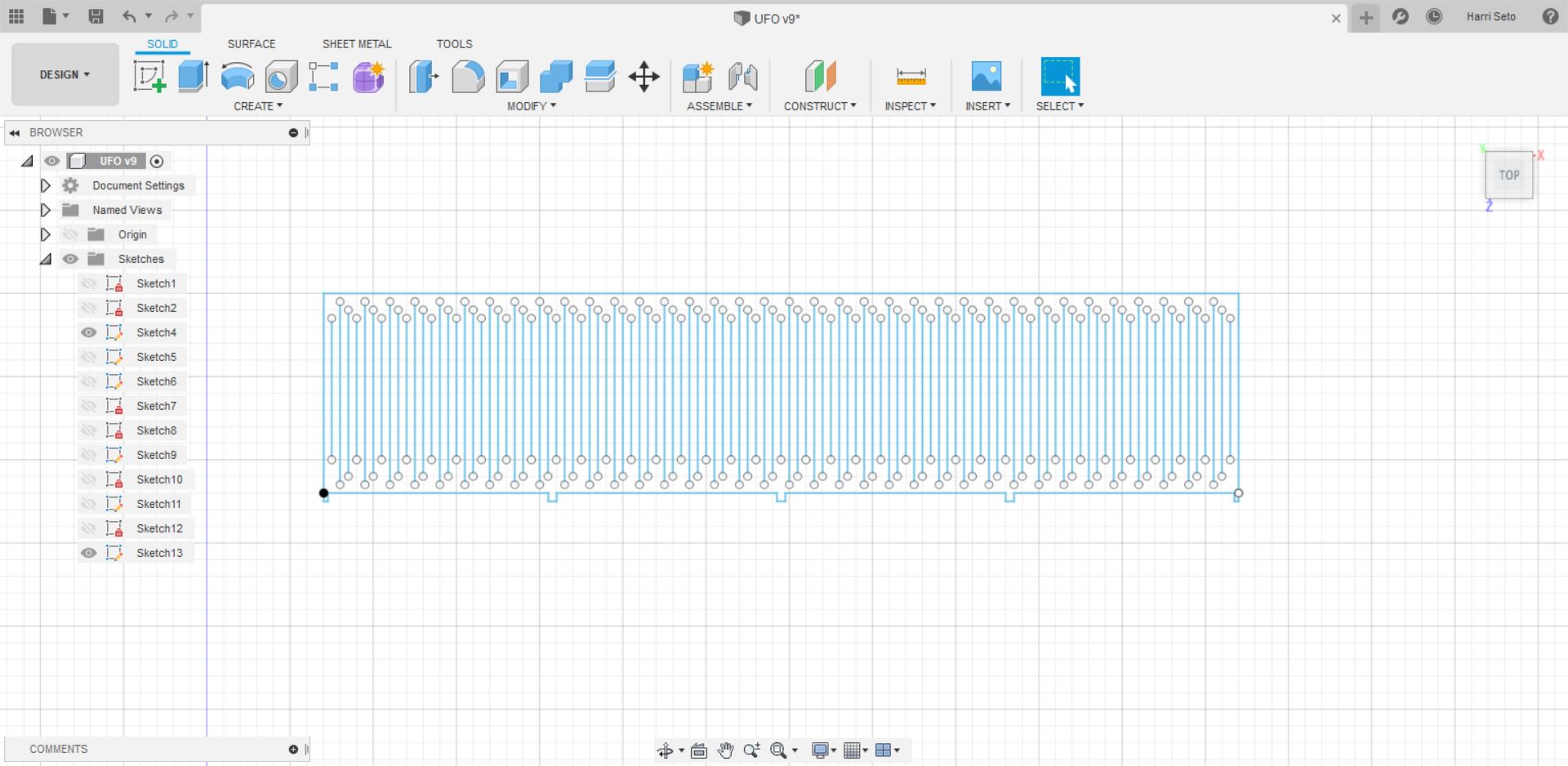
After I did this, I made the second living hinge part which looks like this
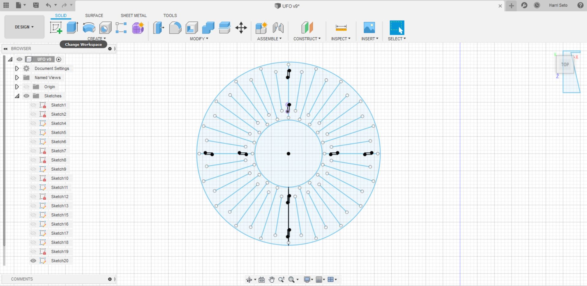
After I was able to do this, I made the top of my UFO, and some holes for joints so that it can be connected to the cylinder I just previously made.
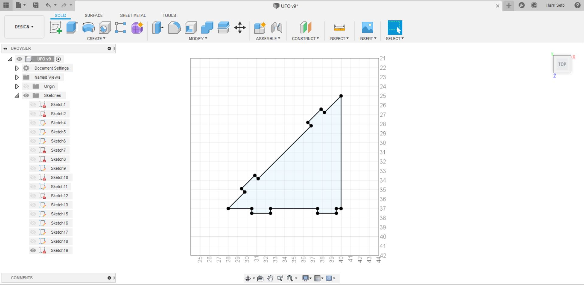
After I did this, I created slots in my circles, and then I made a triangle piece that would support all of my pieces. The triangle piece looks like this.
Finally, in order to create the floating effect that I wanted to achieve, I created some legs that would be connected to the main base which I had built (step 1)
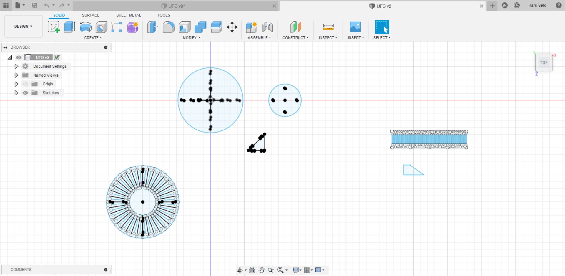
Once I had all of my pieces ready to go, I exported each sketch as a dxf, and I sent them to my laser cutter to cut the pieces out (scaled-down 1:8) to see if the shape would work. All of my pieces together look like this
Once I finished doing this, I realized that I had an error with the wrapping living hinge and I went back to Fusion to fix the error, but I was not able to cut the pieces out of wood due to COVID-19 and the closure of my lab for an indefinite time.
Aspire
Since I do not have access to my lab, I was unable to use aspire, but I have made toolpaths on Aspire before and that was my plan for this cut as well. Alongside the toolpaths, I planned on creating a dogbone or a t bone filet joint for my slots so the pieces would fit together.
Quarantine Update
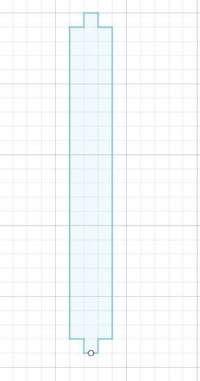
Since the design did not work when I was at the lab, during the quarantine at home, I decided to redesign my UFO so that all the pieces would fit. In order to overcome this obstacle, The first thing that I decided to do was to get rid of the two living hinges, as I realized that wood is very hard to bend in the manner I wanted it to bend, so I came up with an alternative plan. For the cylindrical living hinge, I decided that I would make four posts/ rod like shapes that would fit into the base and top piece, and that piece looks like this:
The next step was to make an alternative design for the living hinge that would have wrapped around the triangular pieces that are placed on the base piece. At first, I thouhgt about getting rid of the triangles completely, and instead I would create circular pieces that would stack on top of eachother in order to make the shape of the UFO. The design would involve creating spacers, which would be 4 circles each 0.5 thick and 4 inches in diameter in order to be 2 inches high, and 4 of these stacks would be spread around the UFO. The space in between the top circle and the bottom circle should be roughly about 11 inches, so I would place 4 and 1/2 spacers and 4 circles in order to complete the space in between the two pieces. But After thinking about the size of the design, I realized that I would be wasting a lot of wood in the process, so I decided that I would stick with a design that involved my triangular pieces.
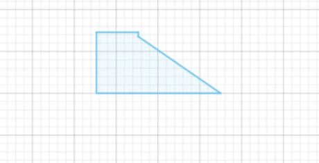
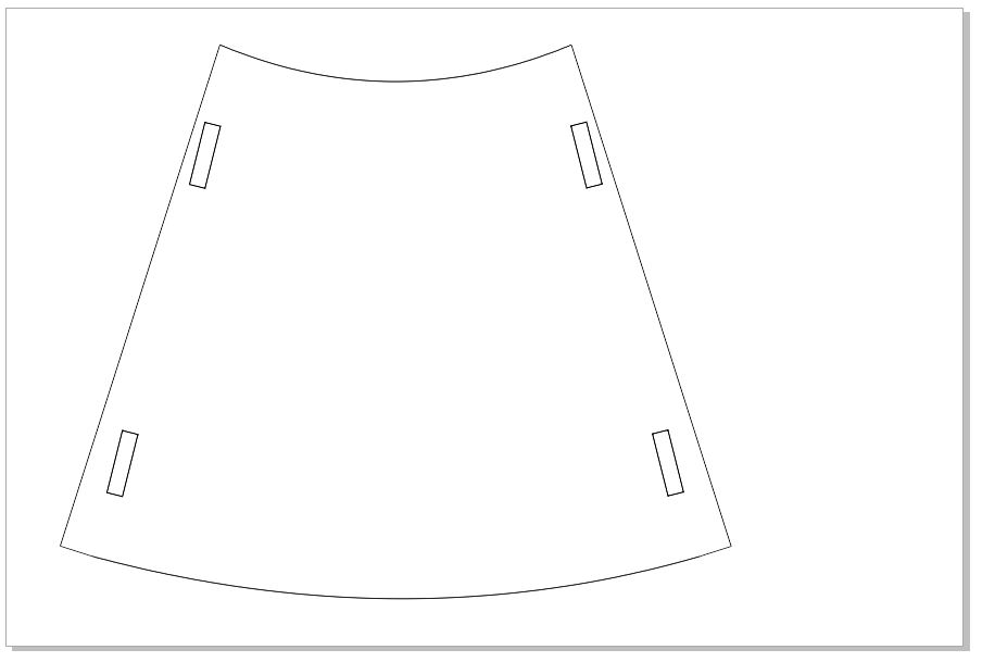
I thought about the designs I could create for a while, and I finally got the idea that I would create 4 more slots for the triangle to go in, which would mean that there are 8 triangular pieces in my design now. I did this becuase I realized that I could turn the design into a book shelf instead of just a decoration. I would create a shape similar to a trapezoid, and I would cut 4 pieces like that out of cardboard so that I could score it in order for it to bend the way I wanted it to, and I will only four of them on there, as it would leave a space in between each slot, so that the structure still had a UFO shape while being able to store books on it. This is what the modified pieces in the design look like.
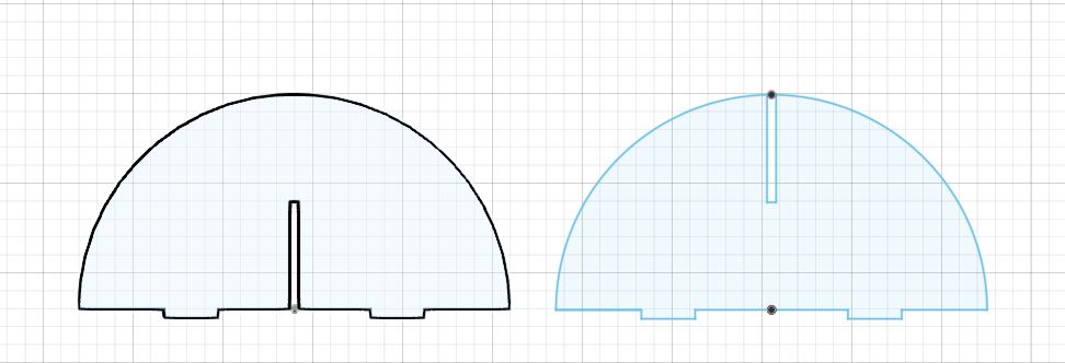
With this, I also created a top dome, which would also act as dividers, as there would be 4 spaces in which books could go in. I decided that I would use the method of creating a slot on the bottom half on one piece and the top half on one piece, which looked like this:
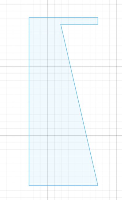
The final adjustment I made was with the legs of the UFO, as I realized that the ones I currently have are too wide, and would not give the structure the floating effect that I wanted. So I modified the design I had and I made sure to make the legs taller/ less wide, and the final design of the leg looks like this:
Back to the Lab
Once we got back to the lab, we had to catch up with some other weeks, but after that was done, I was able to get on Aspire and create my toolpaths for the design that I created, and was able to export my cardboard piece that I wanted to the laser cutter so I would have all the pieces neccesary to build the UFO.
Making toolpaths on Aspire
The first thing that I did was that I got all of my shapes saved as a DXF file, and then I imported them into 2 Aspire Documents.
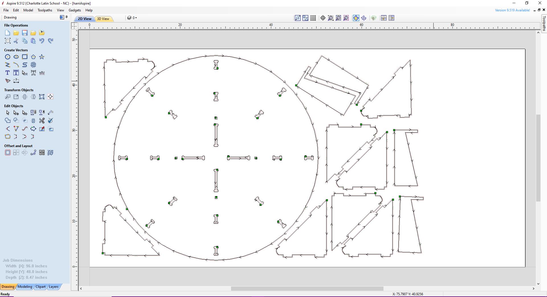
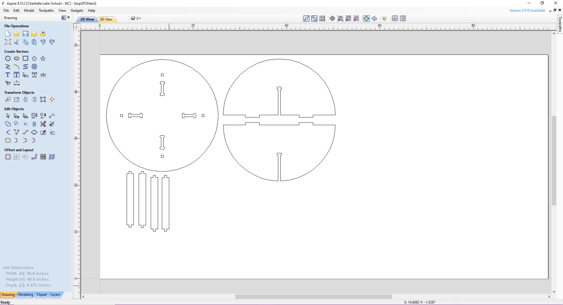
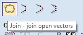
Once I got the pieces into Aspire, I selected all of the pieces and I clicked the button which said to join all vectors
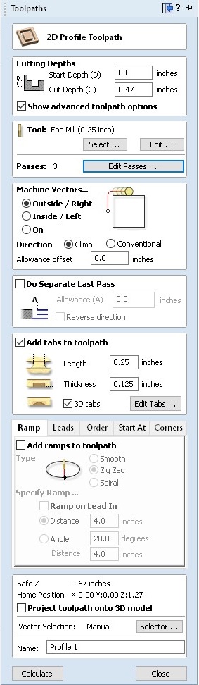
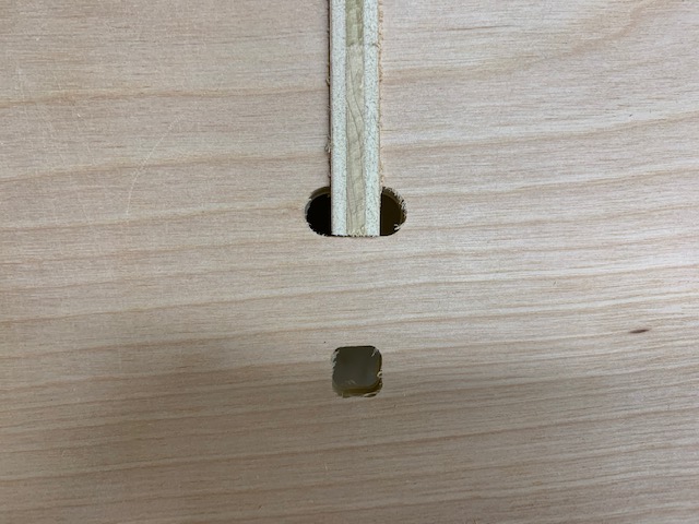
Once this was complete, I looked for any opened vectors, and there were none, so I proceeded to create my t-bone filets. After the filets were complete, it was time for me to create the toolpaths. I clicked on the toolpaths menu button, which pulled out a tab with many different things that I could do which looked like this:
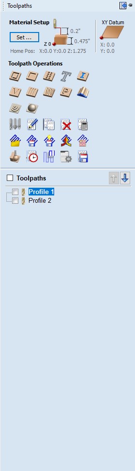
Since my cuts were simple, I only required the profile cut which was done by clicking this button:
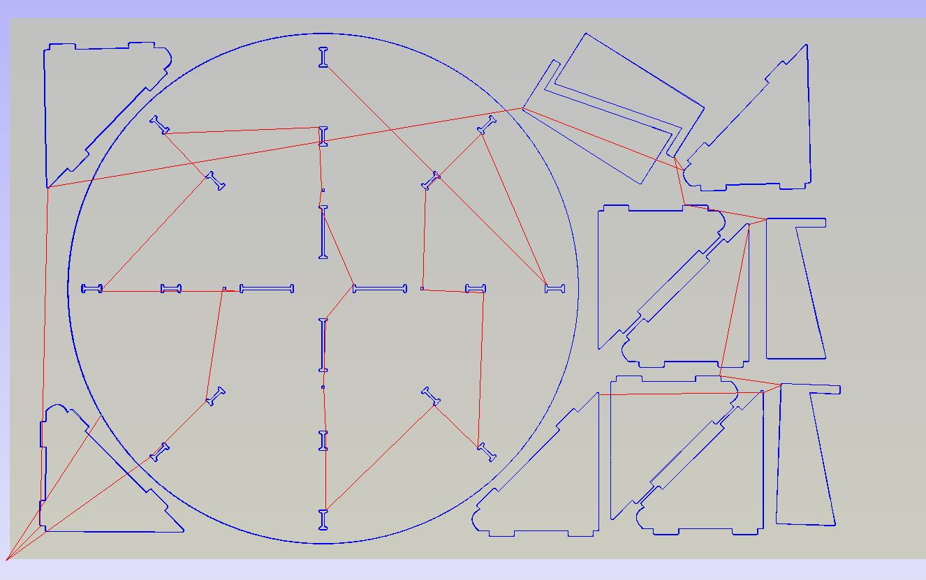
I highlighted all of the parts except for the inside cuts as you have to chose whether the cut is on the outside or inside. I had also changed all of the other values such as the material thickness, as I measured out my wood to be 0.47 inches. I also added tabs to my cut, and changed the amount of passes that my cut would have, and I changed it to be 3 passes instead of 4 in order to save time.
After this was complete, I highlighted the inside pieces and created a toolpath for them. After all of my toolpaths were complete, I previewed them in the 3D view, which looks like this:
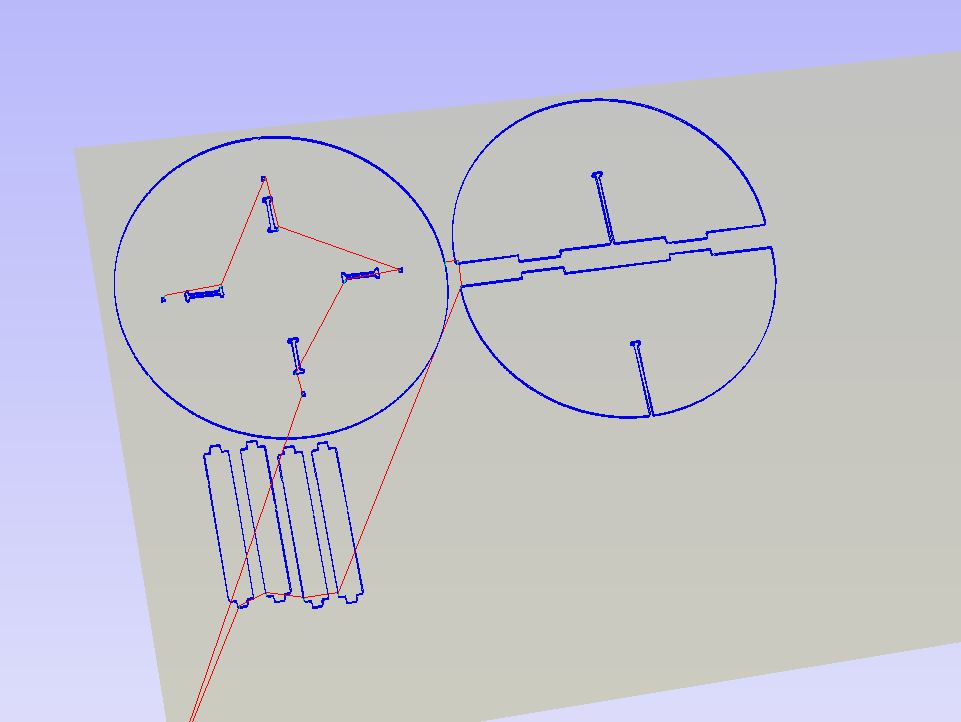
I saw that all of my toolpaths were fine, so I exported the file and got them ready to cut on the ShopBot.
Cutting out my pieces
Once I got my .sbp file loaded on to the computer connected to the ShopBot, and I opened a workflow (shown below) that was made by our Fab Lab Director Mr. Dubick, and got everything set.
1. Shopbot Machine
a. Put on eye and ear protection
b. Close the doors
c. Check to see that the machine has been warmed up
d. Check to see bit is not loose
e. Attach material to the table using screws
f. Calibrate Z AXIS on the table.  (C2 keyboard command)
g. Raise Z AXIS 6 inches using the MZ 6  command
h. Use the proximity switch to set Orgin.  (C3 keyboard command)
i. Set new X and Y Origins for your design
   i. Raise the Z-axis so the bit won’t drag on the table
   ii. Using keyboard move to the appropriate X and Y location. (M2 X,Y)
   iii. Using keyboard to zero the appropriate X and Y Location. (Z2)
   iv. You set origin.
j. Select Cut

2. Start up Aspire and VCarve software
a. Open your file
b. Select objects you wish to cut
c. Select Toolpath
d. Pin Toolpath

3. Click on material setup
a. Check Z-0
b. make sure it agrees with your Z-0 when you calibrated it
c. did you 0 off the board or off the material
d. Enter the thickness of the material *
   i. Model position material should be the same thickness of the material.
e. Go to home start position
   i. Confirm  x and y axis are both  zero
   ii. The z axis should one inch plus the thickness of the material.
f. Click OK.

4. Go to TOOL PATH OPERATIONS

5. Select 2D Profile Toolpath
a. Under cutting depth, select the cut depth of the material (CLS tools).
b. Select the proper tool -CLS down bit 1/4
c. Edit passes, change number of passes from 3 to 5.
d. Under machine vectors, leave default.
e. Click add tabs to tool pads.
   i. Add ramp to tool pad.
f. Hit CALCULATE.
g. Preview toolpath
h. Click on CLOSE
i. Select SAVE TOOL PATH and save the file in a shopbot format

6. Start ShopBot Command Console

7. Conduct air cut
a. Select FILE-LOAD
b. Load the appropriate file
c. Select 1 3-D offset
d. Press ENTER
e. Turn on the spindle by pressing the big GREEN Button
f. You should hear a  “SOUND” of the spindle now turning
g. Press ok
h. After checking that everything is good press space bar
i. Return to origin (M2 0,0)

8. Perform cut
a. Select FILE-LOAD
b. Load the appropriate file
c. Select no offset rather than 1 3-D offset
d. Press enter
e. Turn on the spindle by pressing the GREEN Button
f. You should hear a  “SOUND”
g. Turn on the vaccum
h. Press enter again to start cut

9. Cut is done
Turn off fan (which is so loud you shouldn’t forget)

10. Clean up after yourself
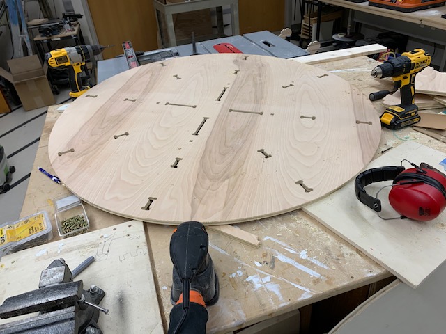
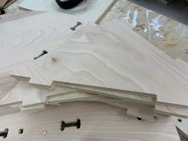
Following the steps, I got ready to cut by screwing on a new sheet of half inch wood onto the bed. Once I got the piece of wood set on the bed, I warmed up the spindle, homed the x,y, and z planes, and I tried out my cut with a 3D offset, also known as an aircut, to see if everything was ok, which it seemed it was,and I got to the actual cutting. I carried through the rest of the steps listed, and cnce all my pieces were cut, I got on top of the ShopBot, and I sanded down everything with the sander, since it would be easier with everything still intact on the bed.
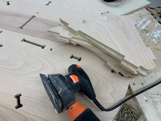
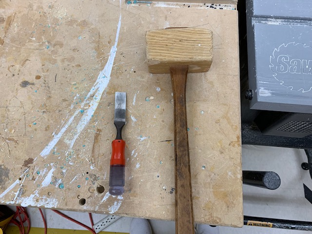
Once this was done, I grabbed a malet and a chisel in order to chip the tabs that I had set.

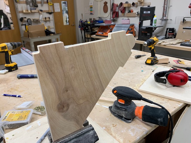
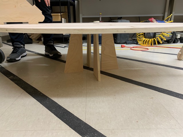
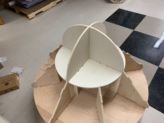
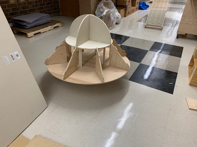
After this was done, I sanded down some of the edges on all of the pieces, and then I fitted the legs onto the the circular base first:
Everything looked pretty good, so now it was time for me to cut out the cardboard pieces on the laser cutter
Cardboard aspect
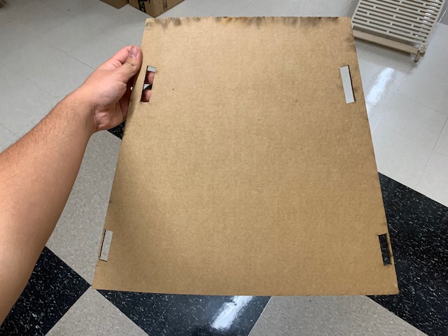
As soon as my cut was complete, I got my trapezoid like piece uploaded to the computer connected to the laser cutter and I got some cardboard and cut out the piece that I needed. After the piece was cut out, I scored it, hoping for a curved shape. The piece ended up looking like this:
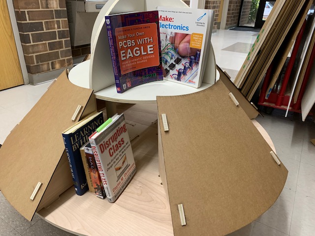
I went to fit the piece on the structure that I had, and it did not look bad, but I knew there was more I could do in order to make it look better. I decided that I would use curved lines instead of straight lines because then the pieces would seem to flow along with the base and top circles that are on the UFO. I went to go cut the piece out and it turned out well and it looked like this:
With this, I had all of my pieces, and the final UFO ended up looking like this:
Summary
Although we did not get to finish cutting this week in one week, I enjoyed the process of getting to use the CNC machine and learning about all of the different techniques that we could use for joining pieces together. In the future, I would definitely like to learn more techniques on joints and look forwards to making more cool things with the knowledge I have obtained with this week. I also learned that changing ideas while designing should be expected and to always be open to creating a new design.
Files
Here are my files for this week Files