12. Output devices
Introduction
This week, we were assigned two assignments, with one being a group assignment and the other an individual assignment. The group assignment for this week was to measure the power consumption of an output device. The individual assignment for this week was to add an output device to a microcontroller board you’ve designed and program it to do something.
Individual Assignment
Due to the current situation, I decided to start with the individual assignments as I had done previously. The first thing I did was that I looked at my final project to see if I could do anything this week that would help me later on to finish. Immediately, it was clear to me that I should work on a motor control board, as that was a part that I could do this week, and is a crucial part of my project. After deciding that I would work on a motor control board, I looked at Mr. Neil’s example in order to gain a general understanding of what my board and setup will look like. After looking at the example, I went on EAGLE and designed a motor control board using the ATTiny 412 microcontroller.
Making the parts
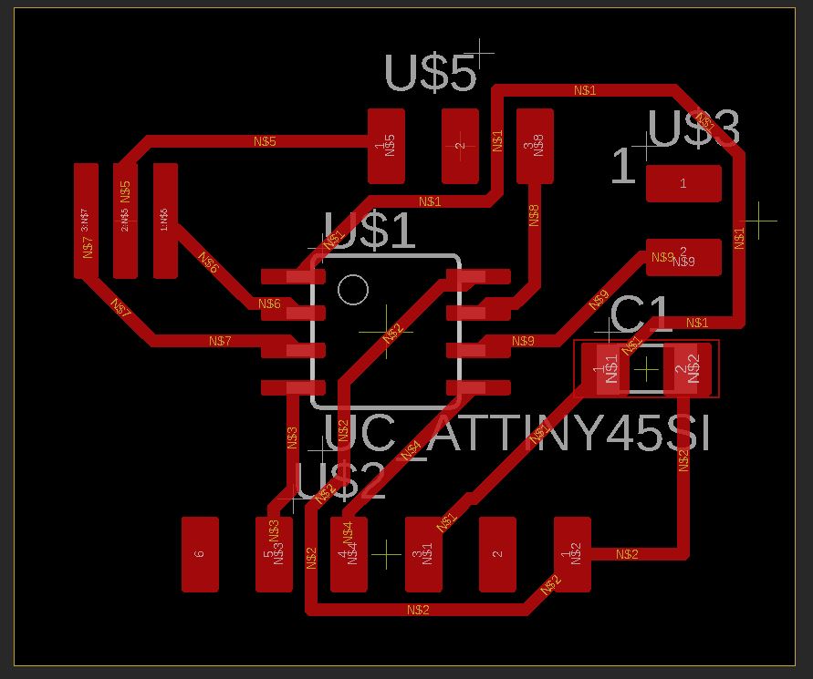
The first thing I did was that I designed my board, similar to what I did with input devices. I looked at Mr. Neil’s design and heard what he commented about brushless motors in the weekly presentation, and then I got a general idea of what I needed to do. I got all of the necessary components for my board on EAGLE, then I made all my traces. I then moved my schematic into a board file, and then applied the 1/64th drc file, and then hit the autoroute. After that was complete, I adjusted the size of the board, and my final board looked like this
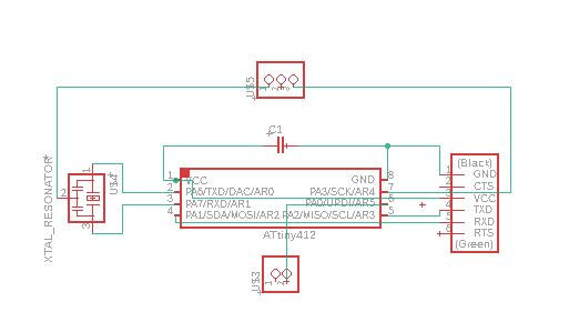
After I completed making my board, I realized there was one part that I did not understand the purpose of, being the crystal resonator, so I decided to do more research on it. After a little while of research, I came to know that there were multiple names for the device, as it is also called a crystal oscillator or just a crystal. I found out that this device uses the mechanical resonance of a vibrating crystal to create an electrical signal with a precise frequency. This means that the device controls the frequency of the signals on the circuit, and the one that I am using has a 20Mhz frequency, which means that 20 million cycles occur in one second, which is crazy to think about! This also led me to do more research about the different terms I came across, such as duty cycle, and a big one, pulse width modulation (PWM). I watched this video which explained to me the difference between Duty cycle,frequency, and pulse width modulation. I learned that the duty cycle was the percentage of the time the cycle was turned “on”. For example, if a cycle is on for 50% of the time, the duty cycle is 50%. The second thing that I learned was frequency, which I explained above. The third thing that I learned from this video was about pulse width, which was explained a little bit in the lecture, but in this video, I learned that it is the elapsed time between the rising and falling edges of a single pulse. To make this measurement repeatable and accurate, we use the 50% power level as the reference points.
Making the code
As we are stuck at home, I have sent my board to our instructors to get milled out, but during that time, I decided to create some simple code that would run the bldc to see if my board worked. Down below is my code that I will use with an arduino and then eventually my board (the only difference being the port which I would attach ESC to).
#include <Servo.h>

Servo ESC;

void setup(){
  ESC.attach(9);
}

void loop(){
  ESC.write(90);
}
Soldering and uploading the code
Once I had completed all of this, I finally got my board and parts so that I could stuff the board. I soldered all my components onto my board, and then I grabbed the bldc, an ESC, and an Arduino and went to test my code. When I uploaded my code, it did not work, which left me very confused as I did not know what I had done wrong. I decided to do a search on the internet and across multiple sources, I learned that the bldc motor needed calibration, and that could be done by entering a low value between 0 and 180 and then a higher value between 0 and 180. I then went to upload the value of 40 then 90, and then my bldc started spinning!
Using my board
After I knew that my code worked using an arduino, I got a updi programmer and then I looked at my ports and changed it and made it so that it would be the correct one in accordance with my ATTiny 412. I repeated the same process of uploading a low value, then a high value, and my board worked!
Group Assignment
Here is the link to the group assignment for this week.
Files
Here are my files for this week