18. Machine and Mechanical design
Introduction
This week our assignment was a group project in which we had to design a machine that includes a mechanism+actuation+automation, and then to actuate and automate the machine.
Brainstorming
The first thing that we did as a group was that we hopped on a call and talked through some possible ideas that we had for what we would do this week. Everyone was fairly new to the concepts this week, so we decided to look at existing machine designs and what previous fab academy students had made, some of which were mentioned in the lecture this week. After brainstorming and listing out the ideas that we had, we decided to create an automated cupcake batter dispenser, which was inspired by the pancake dispenser in this video.
The design
After we decided to make a cupcake batter dispenser, we talked through the things that we would need in order to make the machine. We had a rough idea that it would be a 2 axis machine with a release mechanism that would work by pushing on a handle that would release the batter from this container. After a general idea was established, we decided to split up and I decided to work on the release mechanism along with my fellow fab mate Vincent Zhou.
The release mechanism
There were many ideas for a possible release mechanism, some of which included a rotating lid with a hole that would release the batter once it aligned with the nozzle and a mechanism to squeeze a bottle that would release the batter. After looking at the many possibilities, we decided that we would purchase this dispenser, which is activated by pulling on the handle as shown below.

Although this is easy for a human to complete, we now had to figure out a way in which the machine would be able to do this. After thinking through a few designs, I realized that the original pancake machine in which we took our inspiration from used a simple and easy way to release the batter, which seemed to be a part attached to some sort of motor which rotated and pushed against the handle when commanded.
Designing the push part
After deciding on the concept, I went over to Fusion 360, and looked and designed a basic shape of what I wanted the part to look like. Since I did not have the measurements of the gantry nor the location of the dispenser, I just went with estimated values.
Vincent also made a design, and we compared designs, picking the best parts from each, and we ended up using the clamp that Vincent designed and the dispensing mechanism that I designed.
Getting the parts
After designing the parts, we had to wait for the parts such as the dispenser to come in, and I was informed that the group that was making the gcode for all the motors were going to use a stepper motor called the 28BYJ-48. Since this stepper was in the lab, I grabbed a motor driver board and an arudino and experimented with it. After using some simple code to just get it spinning, I realized that the torque of the motor was no where near what we needed it to be. After that, I tried modifying a few things here and there with the code to see if I could make the motor work with my design, but unfortunately, the motor would not work for this application.
A change of plans
With this, I needed a solution, and I looked around the lab and figured that my original idea of using a servo motor would be perfect. At the same time, William Zhou decided to work with me, as he was creating a board for this week to mill out, but realized that it was not needed. We looked around the shop for some servos to work with, and I found the HS-475HB Servo Motor that we estimated had a high enough torque (estimated by looking at size and confirmed by looking up servo specs), and we decided to put on a metal attatchment that is usually used tetrix for but was perfect for our application as well.
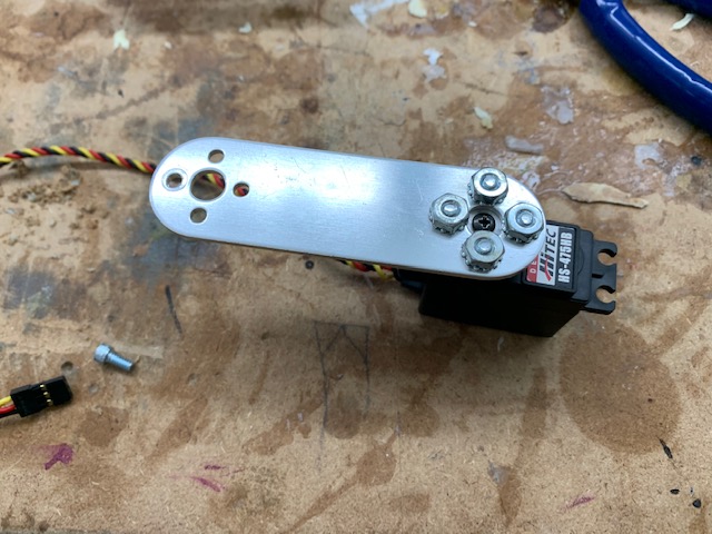
After getting an arduino, I uploaded the same code that I used for my BLDC’s (as they both use the servo.h library) and made sure the servo worked. After confirming that it worked, we moved on to see how to fit the mechanism onto the mount.
Testing parts
As soon as the parts came in, we examined the dispenser in order to see things such as where we should place the mechanism, and to test if the servo could push over the trigger. We saw that the very bottom of the handle was where it was the easiest to push, so we decided to put the mechanism there. After that, we grabbed the servo, and tried to push the handle with it and here were the results:
Although the servo could push over the trigger a little bit, we realized that it would be better if we had something that would be more consistent.
Release mechanism v2
After a little bit of thinking, we realized that it would be best if we created a swing arm that would cover and uncover the nozzle at the bottom of the dispenser, which was an original idea that we had. Then, we both got on Fusion and created a design that would go around the clamp that Vincent designed. We took the measurements from Vincent’s file and we made an enclosure that looked like this:
After making the 3D print, we got some screws and nuts and attatched everything together, and here are some images of how that turned out:


We also made 2 different pieces that goes on the servo arm in order to stop the batter. These pieces are made out of regular PLA right now, but the lab has food safe PLA ready to use, which we will print and use as soon as the final design is decided upon.
The first design is a curved piece like this:

The second design is a simple flat piece like this:

After everything was printed and screwed on, we tried running the motor to see how it would work and here are the results for the first type:
Here are the results from the second type:
It is evident that the second type works a lot better, and therefore we will be using that for the final product!
Moving the Gantry
Since we finsihed the mechanism before the gantry was moving, I decided to look into the G-code that was actually running the machine. To start off, I found an informative website which explained what each of the letters meant in the code, so I would be able to understand what is going on. Since William seemed to have everything going well, I decided to do a bit of experimentation myself. I thought about what I could do in order to test out some functions in the G-code, and I came across NC Viewer, which is a G-code viewer and simulator. To start off, I took one of the G-code files that William had put on a Google Drive, and I tested it out, and the machine seemed to do everything that he was testing, which I thought was cool, since you could simulate your files before actually testing them. After this, I made a couple of functions myself to see what would happen, and to just see how everything works. It was fun, and I definitely would like to try to make some sort of machine on a smaller scale in the future for fun!
Group Page
Here is a link to the collective group page where you can see the overall documentation and what everyone else did
Files
Here are all of my files from this week.