4. Computer controlled cutting
Intro
This week, our assignment was different, as we had both an individual assignment, as well as a group assignment. For the individual assignment this week, we were to create something on the vinyl cutter and to create a parametric press-fit construction kit.
Vinyl Sticker
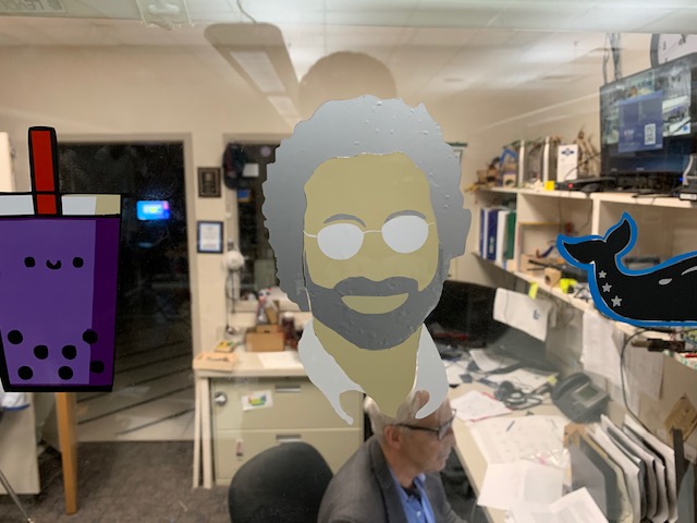
For this week, one of the things that we had to do was to create a vinyl sticker. After brainstorming for a bit, I decided that I would make a sticker of Neil Gershenfeld’s face. To start off, I decided to take a Google search of Mr. Gershenfeld. I looked in the images to get a good look at how I should make the sketch. I finally decided that I would import the image down below into CorelDraw and start from there.

Once I had the image imported, I was able to get the trace outline feature working, and I decided to make a detailed logo

Since this image was not perfect, I decided that I would make fixes with the freehand tool. After I drew the lines, I realized the image was still too complex, and that I would have to make some changes. I decided that I would choose a different image to complete the task, so I went back to Google and found this image.

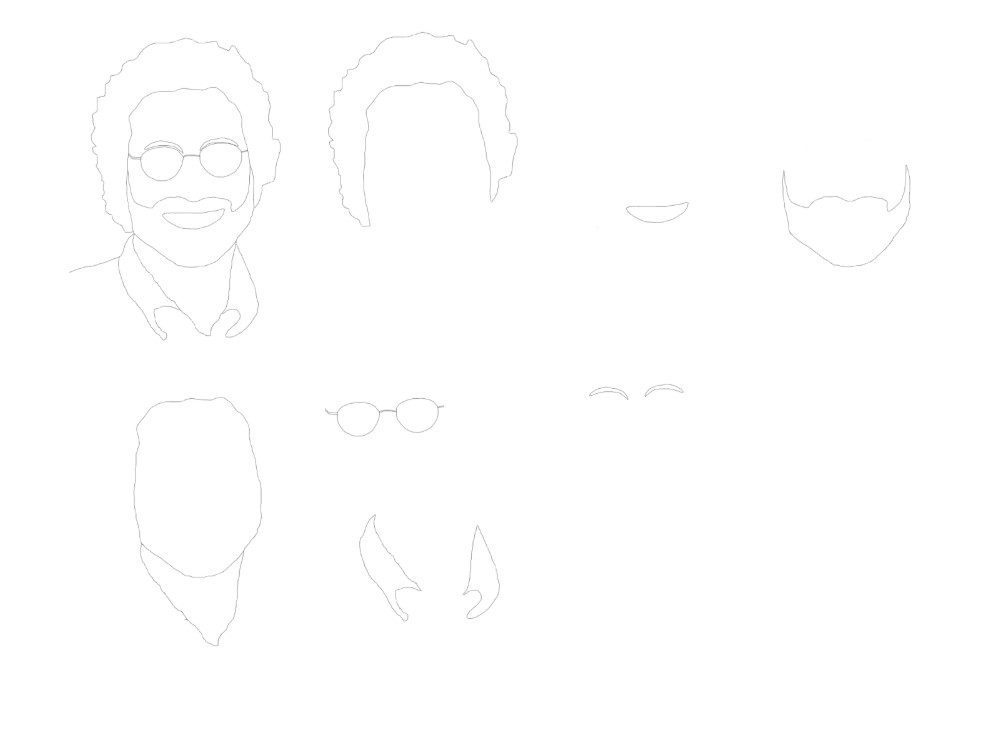
Once I had completed this step, I went on to make a line art this time, and it was also not perfect, so I used the freehand tool to fix the rest of the issues. After I had completed this step, I realized that I would need to trace some unclosed lines, and I did so. After that, I felt like the product was done, I uploaded my work and went over to the vinyl cutter to make my cuts. Everything was going fine until I opened the file on Silhouette, and I saw the issue that the cuts were formed weirdly and that they were too thick because the way that line art is formed. With this, I went back and decided that I would use the freehand tool in order to make the whole sketch. In order to help with this, I changed the opacity of the image and changed it so that the image looked like an x-ray image. Once I was finished tracing, I uploaded my work back up and started making the sticker. I had also spread the drawing into pieces so I could cut it easier.
I started by getting pieces of vinyl that I would want

Then, I got a mat, and placed my piece of vinyl on the mat
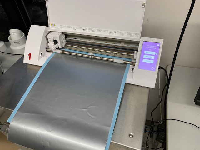
After that, I hit the button that said load cut mat, after I had lined the mat up
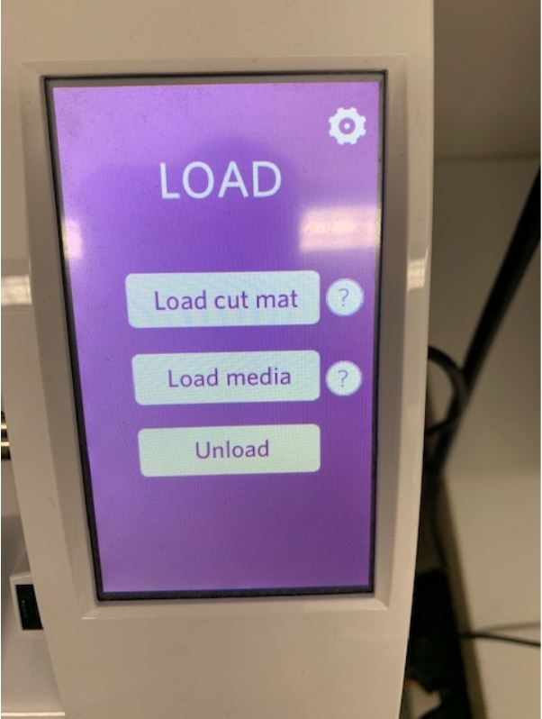
Once everthing was in place, and I sent the file to cut, I waited for it to finish, and then, I hit unload.

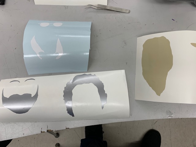
I cut out my pieces and had them all peeled off, ready to go on the transfer paper.
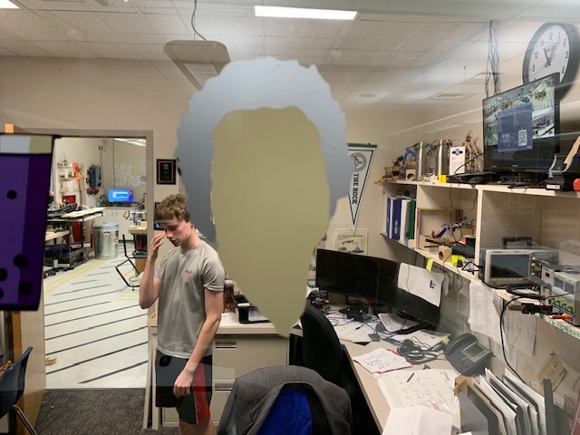
I started off by placing down the hair and the face, which looked like this
Then, I proceeded to place the beard and eybrows
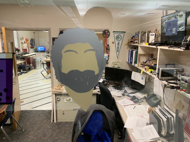
While I was placing down the beard and eyebrows, I felt that something didn’t feel right, and after I placed it, I went back and looked at the file on Silhouette, and realized that I had cut out a bigger version of that piece, as I had resized the face on Silhouette due to space. I cut out the correct version, and removed the old, and the fixed version looks like this
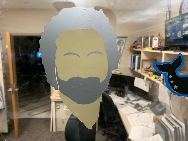
Once I completed this, I proceeded to place glasses and collar
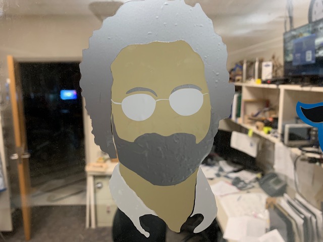
After that, I went on to place the mouth, and the sticker was complete!
Group Project
After I completed my vinyl sticker, our group decided that we would work on our group project. For the group project, we had to characterize our laser cutter’s speed, power, focus, kerf, and joint clearance. We learned a lot from figuring these characteristics, as we didn’t have too much experience or knowledge with them, but as we researched and talked as a group, it became more clear. For this project, I helped with the color mapping on the design, the design for the fixed cut, and the actual cutting on the laser cutter. You can find our group page here
Laser Cutter
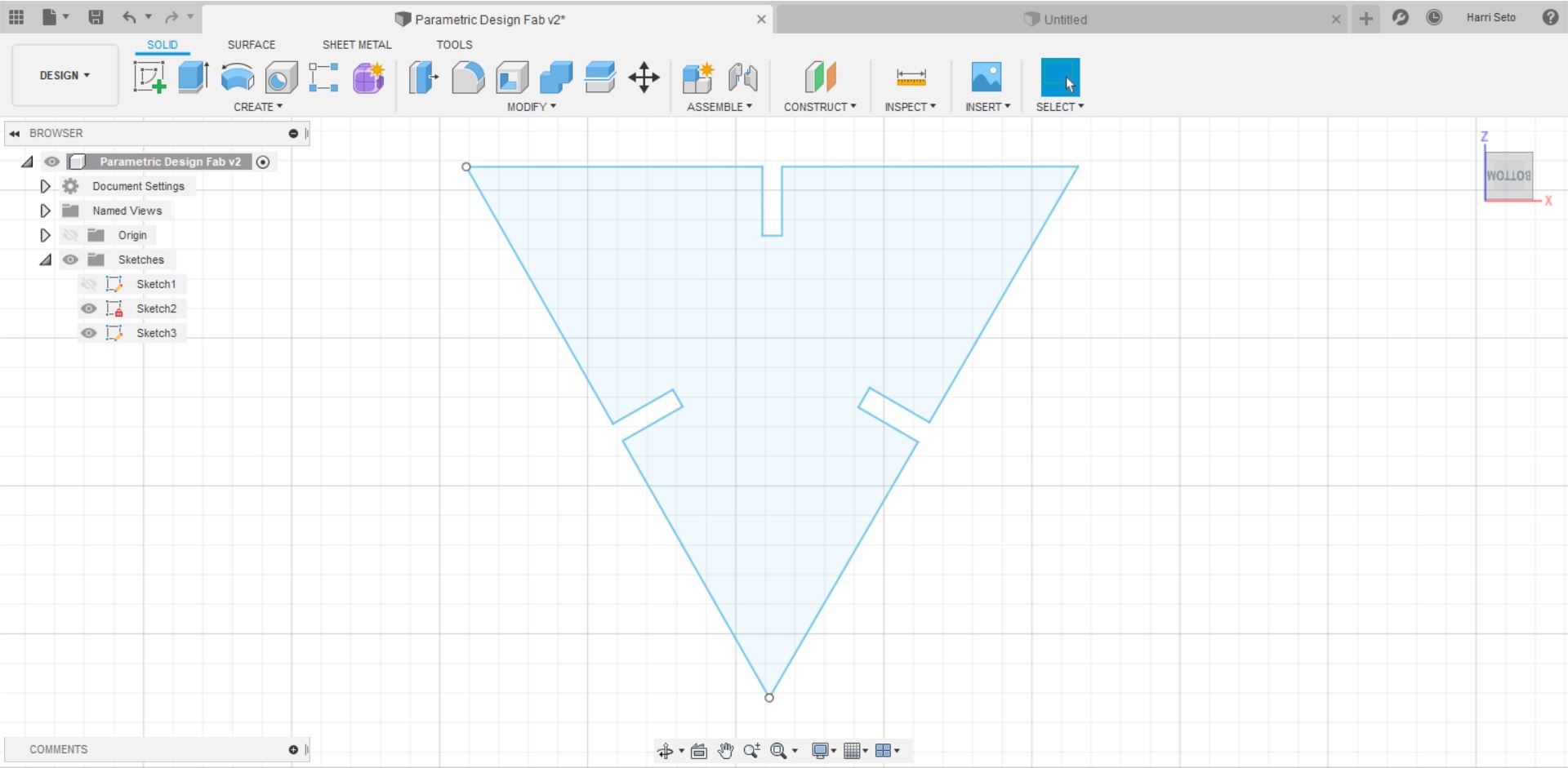
Another thing that we were assigned to do this week was to create a parametric design, then cut it out on the laser cutter. To start off, I decided to look at some examples of parametric designs that have been completed in previous years. After I felt that I got a sense of what to create, I opened up Fusion 360 and started my parametric design. To start, I created a sketch, and then I clicked edit sketch
Once I was in the edit sketch menu, I was able to access the dimension tool, which would be needed to create the parametric design, which looks like this

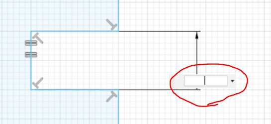
Once I was in the dimension tool mode, I clicked on an edge, and dragged my mouse to the side in order for the measurement to show up. I then prompted me to enter in a value, which looks like this
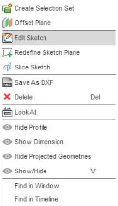
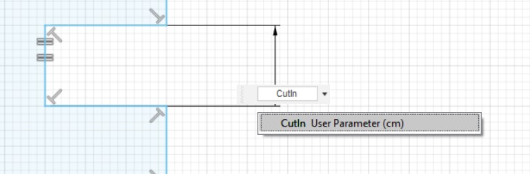
Once this was there, I would click and enter no value. I then went to the modify dropdown at the top, and I selected Change Parameters, which was at the bottom, and a menu like this would show up.
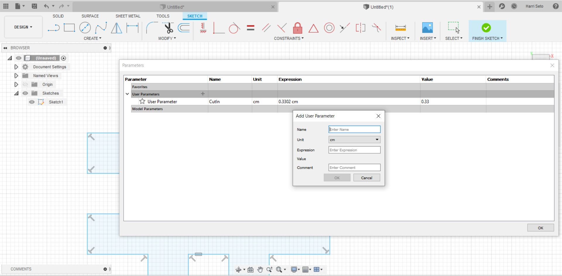
With this, I would add user parameters as I liked, and for this edge I would assign it the name CutIn, since it would be the value of the edge of the part that was cut in. Once I set the value, I clicked on where I pulled the value out with the dimension tool, and I would assign the value to CutIn
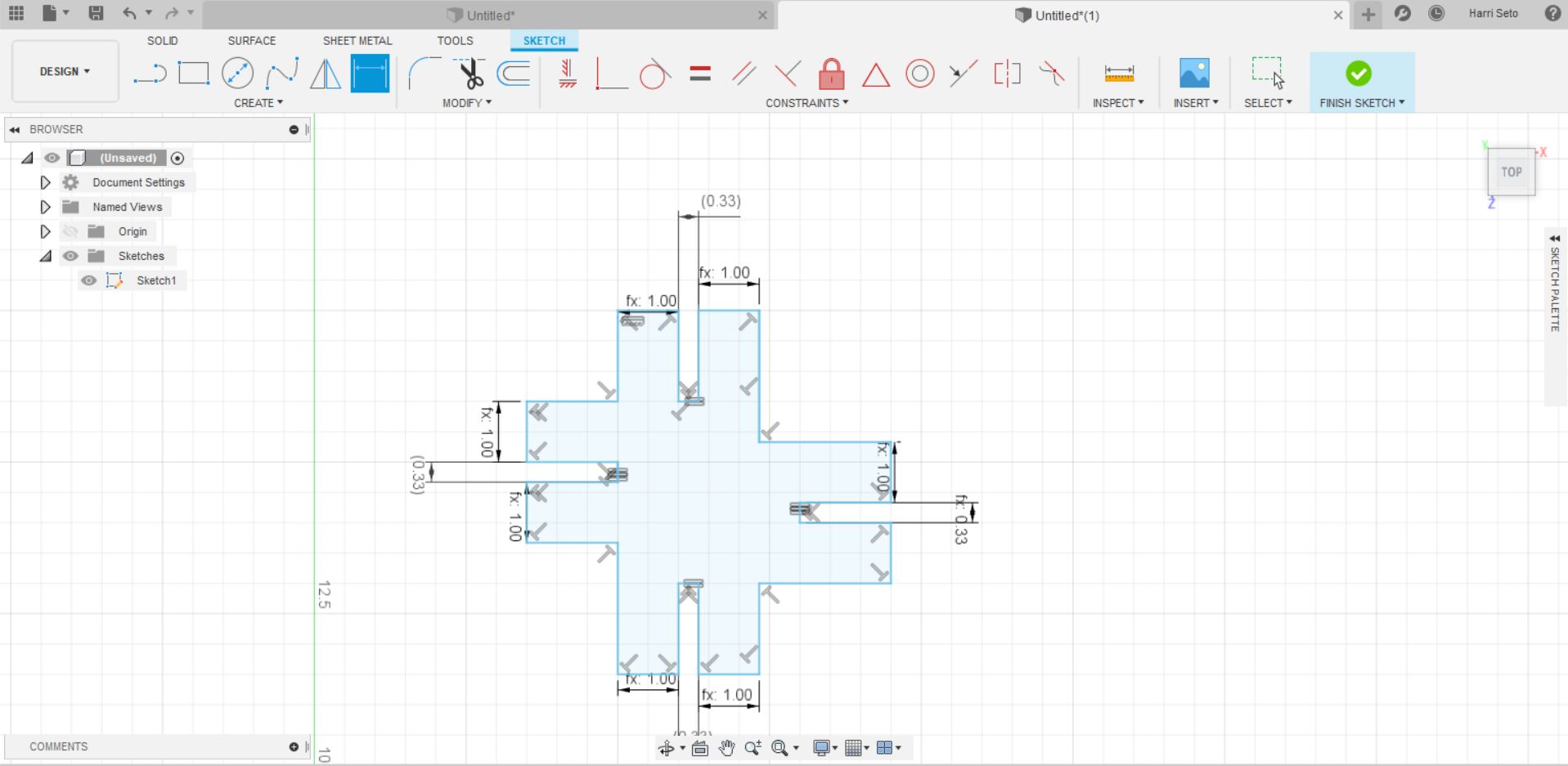
While I was setting my parameters, I realized that while I was assigning dimensions to all of my sides, my shapes would turn into funky shapes like the one below.
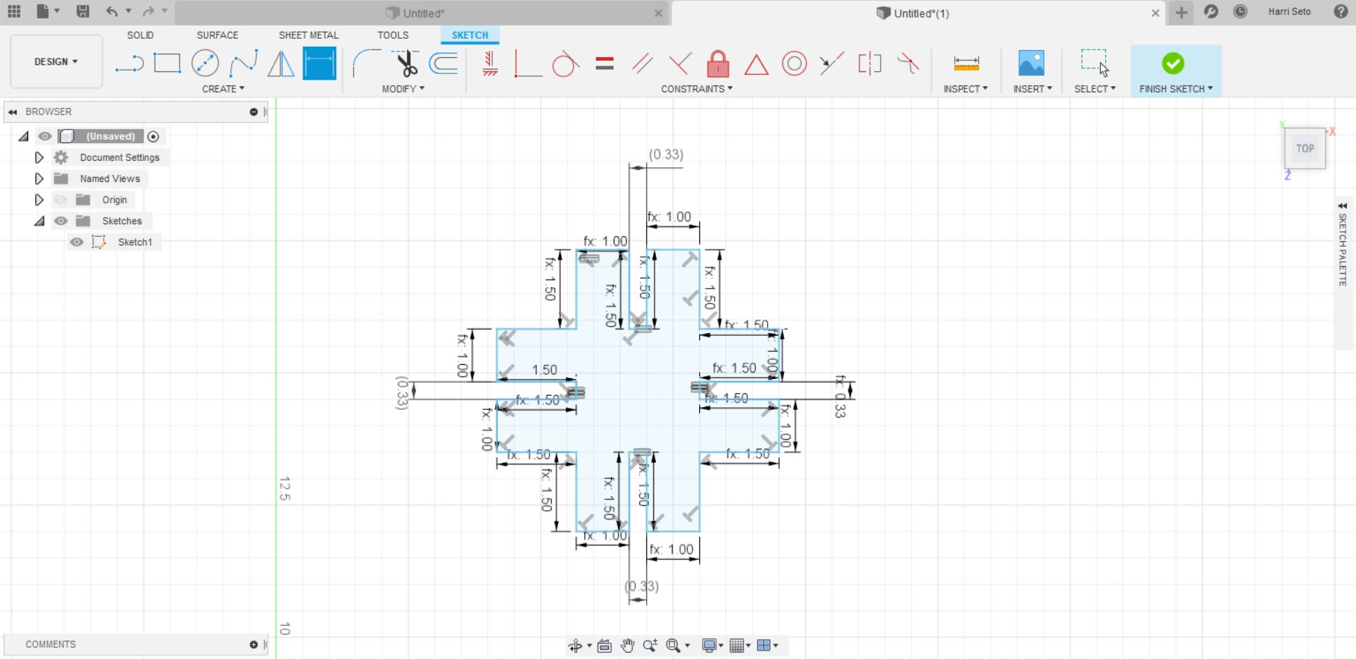
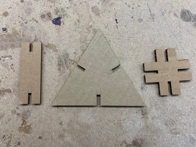
I was able to fix these shapes, and the final design of the first part looks like this
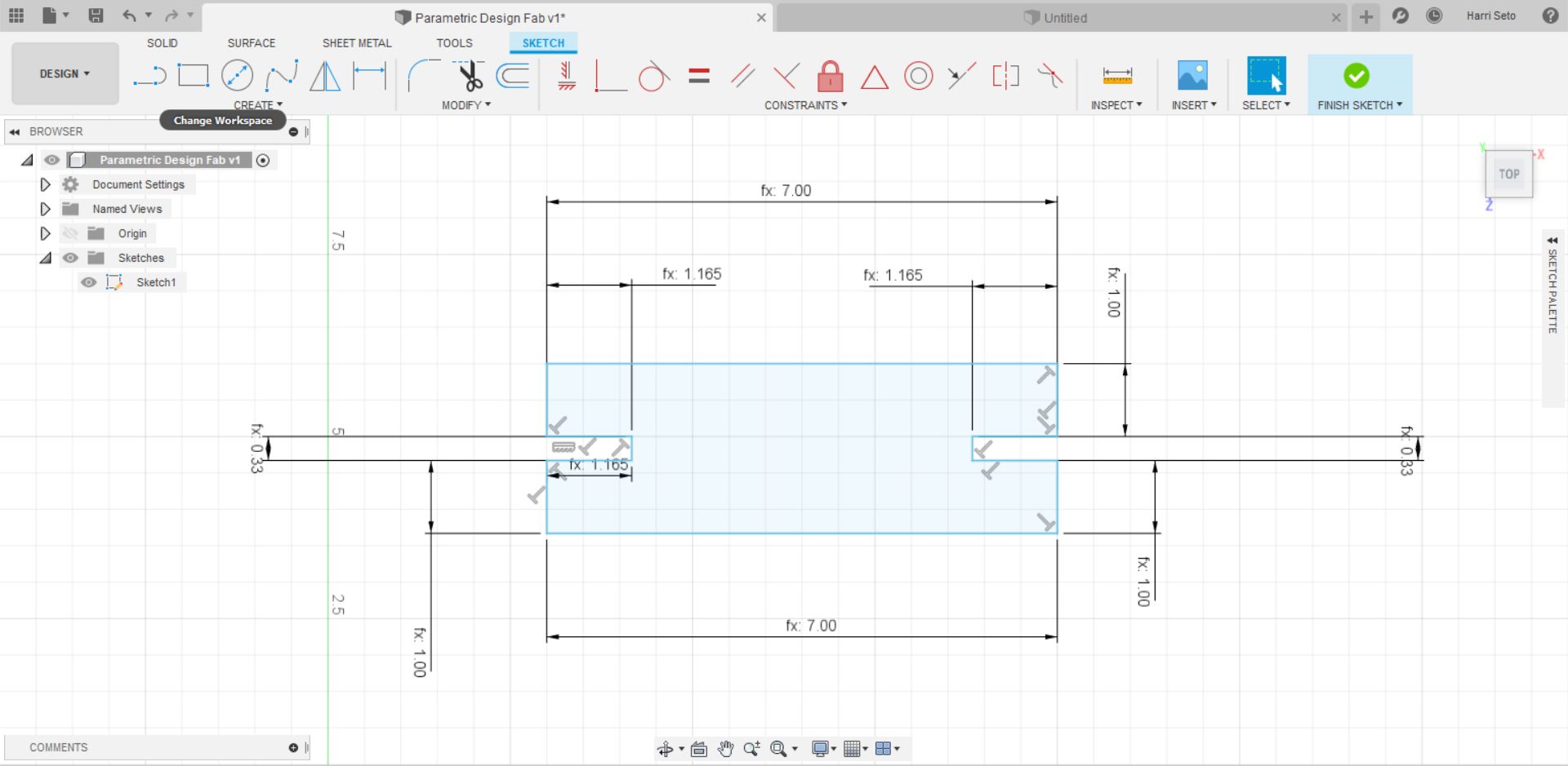
After I completed the first part, I thought that it would be cool if I added another part to my design, so I made another design, which was a simple rectangular shape, and it ended up looking like this.
I felt that I wanted to mix up another shape in as well, so I decided to make another shape, and it looked like this.
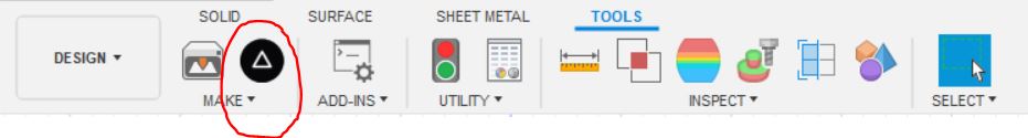
Now that I have completed designing, I need to upload my file to CorelDraw in order for me to be able to cut it out on our laser cutter. In order to do this, I exported my Fusion 360 file by using the shaper tool, which can be found here.
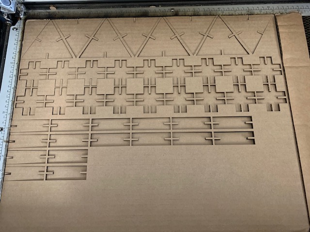
With this tool, I am able to save my drawings as SVG files, which I did, and now I will cut my shapes out. In order to use the laser cutter efficiently, I used a workflow that can be found here. After I had double checked with the workflow, I went into the cut settings on the Epilog Helix and set speed to 15, power to 50, and frequency to 500, and cut. My cut turned out to look like this.
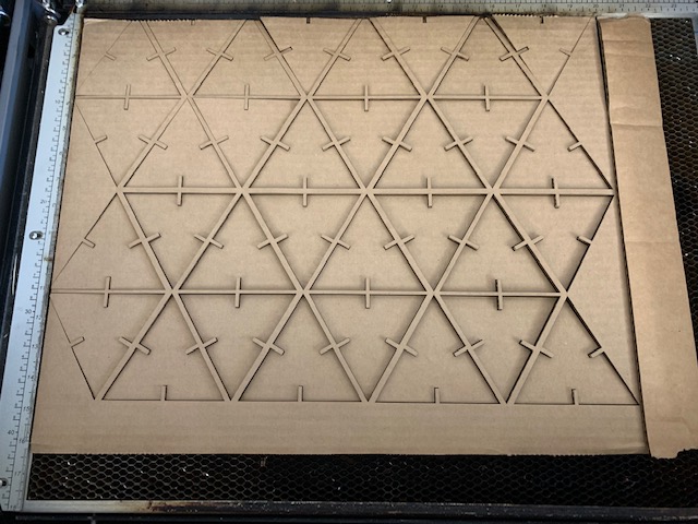
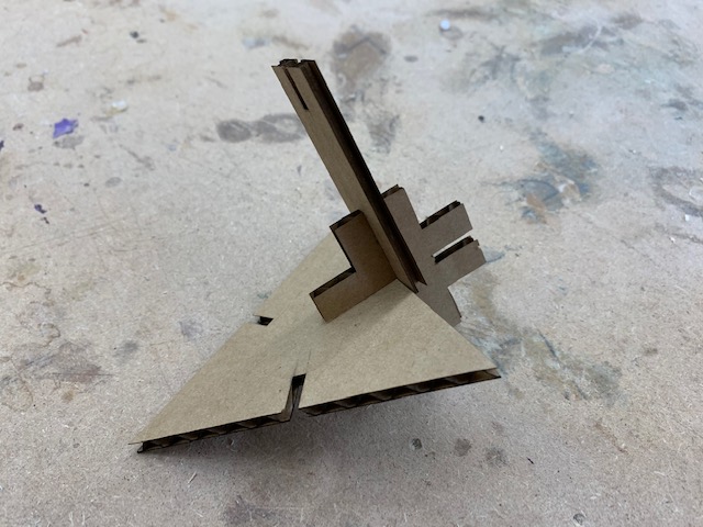
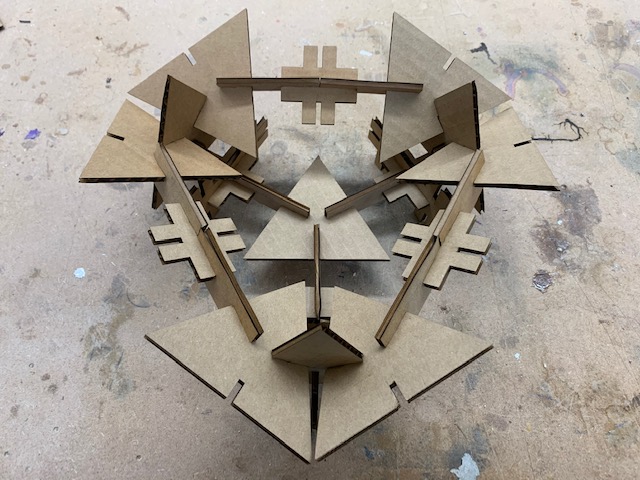
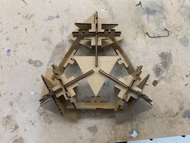
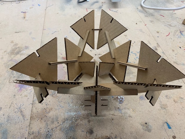
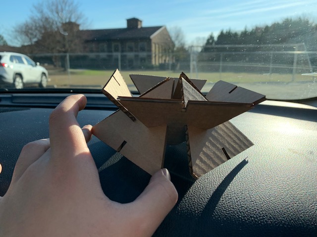
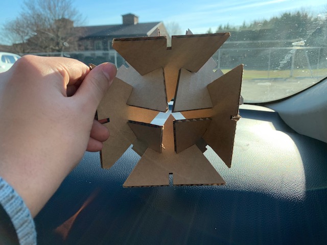
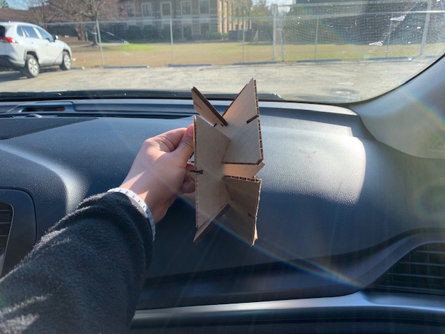
With this, now I will try to make some shapes, and here are some examples of the shapes that I made with my tool kit.

Summary
This week, we learned a lot about parametric design, and things to take into consideration when making your designs. I believe with each of these activities requiring me to make new things, I was able to gain more confidence in my Fusion360 and CorelDraw skills. I had a lot of fun this week making these items, and hope to make more cool things in the future with the skills that I now have. Here are all of my files from this week: Click Here