10. Input devices
Introduction
This week, we had two assignments, one being a group assignment and one being an individual. This week’s group assignment was to probe an input device’s analog levels and digital signals. The individual assignment for this week was for us to measure something: add a sensor to a microcontroller board that you have designed and read it.
Eagle
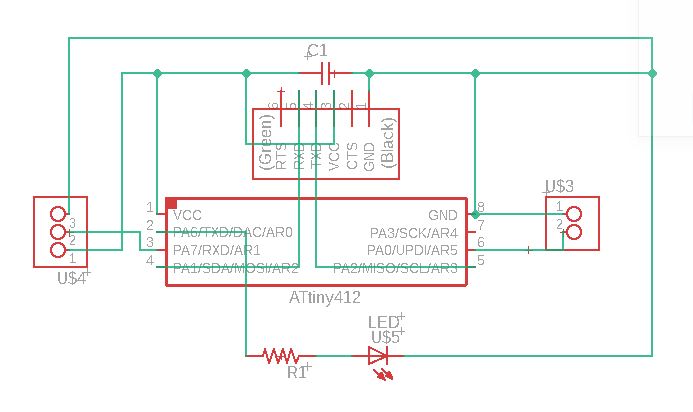
This week, I started with my individual assignment as the COVID-19 pandemic still has us quarantined away from the lab. So with what I had, I started designing a board for a pyroelectric sensor(I used the HC-SR501). The first thing I did was that I went to the Fab Academy website and looked at Mr. Neil’s board. Although he used an ATTiny 45 and I used a 412, I was able to figure out what needed to be connected to what and got my design running. I added all of my parts and made the connections and my schematic looked like this.
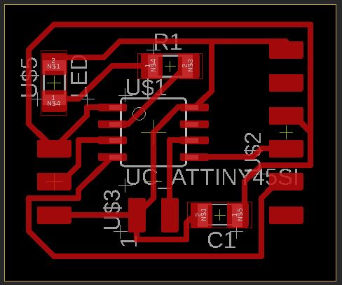
After I was done with this, I saved and switched over to a Board view. I lined up all of my components and was able to get them set to route. I applied my DRC file for the othermill 64th bit, and I was ready to route. I set the autorouter on and chose the best one, which ended up looking like this
I saved my files, and since we could not access the lab, I put them in a folder so that one of the teachers/ instructors at the lab cut mill the board and get the parts to me. Although most of the students live near the school, I happen to live on the other side of the city, which was a bit of an issue, as the city was on lockdown. I was eventually able to get my parts and will start programming.
Programming the board
Although I did not have my board milled out, I decided to create code so that I would have something to work with. I designed my board to have an LED on it, so I decided that I would create a program that would turn on the light if it detected motion. So I went onto Arduino and tried to make functional code
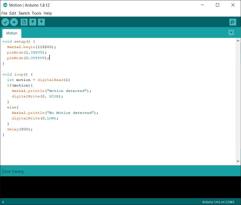
After checking all my ports and my connections based off of my Eagle Files, I saved my code and will test it soon.
Soldering the board
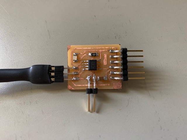
Once I got my board and my components, I soldered on all the parts to my board, which looked like this.
After I was done soldering, it was time for me to upload my code!
HC SR501 Sensor
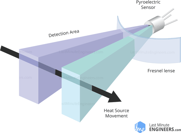
Before uploading my code, I decided to do a little research about the HC SR501 sensor itself, so that I could have a general idea about the sensor. The HC SR501 sensor is a PIR/ pyroelectric sensor, and the funcition of this sensor is to detect motion. I learned that the sensor works by detecting levels of infared radiation emitted (heat energy). There are two main components to the PIR sensor, being the pyroelectric sensor, and the Fresnel lens. The Fresnel lens focuses infrared signals into the pyroelectric sensor, and the pyroelectric sensor has two rectangular slots which allows the infrared radiation to pass to two separate infrared sensor electrodes, with one producing a positive output and thhe othher a negative output. Down below is a diagram of the sensor.
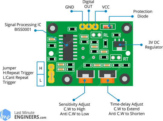
On the same website, I also found a diagram which I thought was very helpful for understanding the board itself and it is shown down below.
Uploading the code
Once I was finished with soldering, I went to upload my code which should blink my surface mount LED and send a message to the serial monitor each time motion was or was not detected. When I uploaded my code, I did run into an odd issue where my code took a long time to upload, and I tried fixing this problem by checking through all of my settings.
After looking through everything, I didn’t detect any problems, but I decided to restart my computer to see if that would help. After restarting my computer, my code ended up uploading much faster, but I ran into an issue as my LED would be on without anything triggering the sensor. I looked into the problem, and I just removed my serial.begin line, and I tried again, and the sensor worked!
Group Project
The link to the group project is here.
Files
Here are my files for this week.