9. Embedded Programming
Group Assignment
To view the group assignment click here.
Individual Assignments
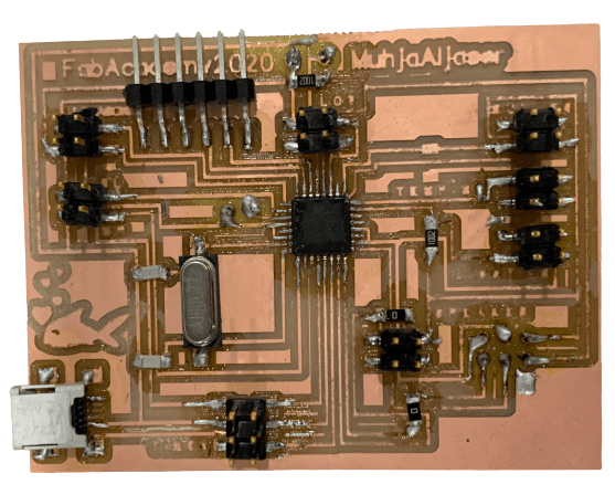
In this assignment, I used the board I made in Electronics Design, which contains the “Attiny44” microcontroller. I will read the datasheet for this microcontroller and I will program it with two programming environments, “Arduino IDE” and “Atmel Studio 7” and with the same code.
Also, in another part, I will connect Arduino UNO with two extra buttons and one LED, and I will be programming my Final Project board that I did in the seventh week.
Programing ATtiny44 PCB using Arduino as ISP
Attiny44 Datasheet
When I read the datasheet, I could not understand several things, as I had not read and had not encountered these terms before. but I found some information that will help me in this week assignment.
Datasheets
Features
- High-performance
- low-power Microchip AVR with 8-bit microcontroller
- High Endurance, Non-volatile Memory Segments
- 4K Bytes of In-System
- Self-programmable Flash Program Memory
Pin Descriptions
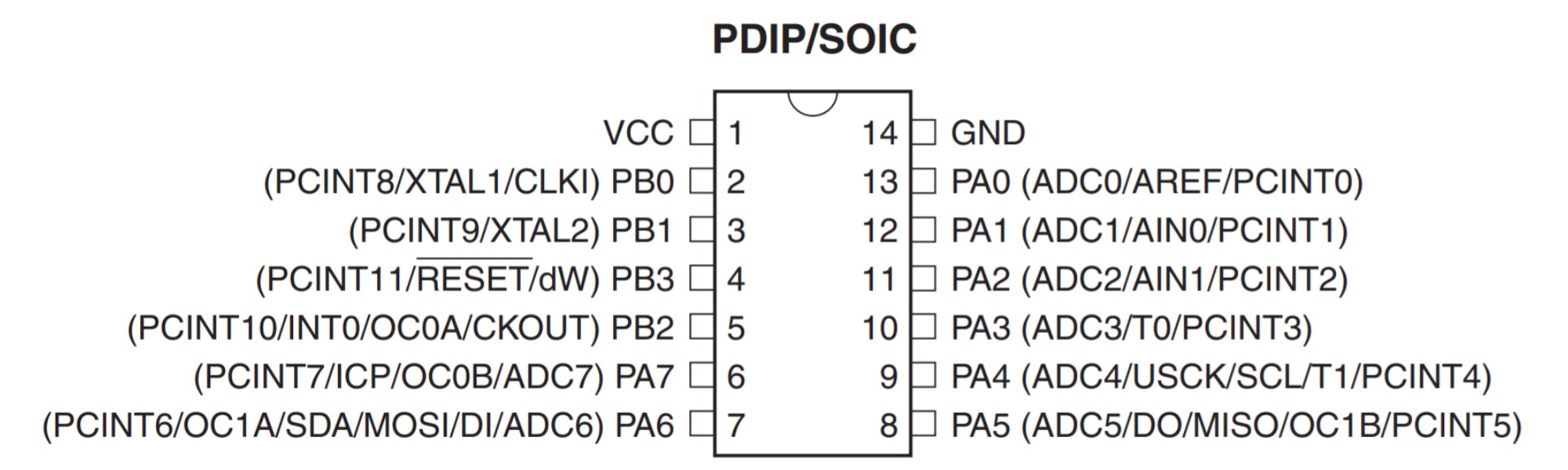
I saw two of pinout package of Attiny44 in the datasheet. The pinout in the picture which I used on my board. We can see that there are 14 pins:
- VCC
- GND
- Port B is a 4-bit(PB3:PB0) bi-directional I/O port. PB3 has the RESET capability
- Reset input pin
- Port A is a 8-bit(PA7:PA0) bi-directional I/O port
All of the ports have internal pull-up resistors
We can read the pins starting from the Notch, or it may be a dot. Pin numbers increase sequentially as we move counter Anti-clockwise around the chip.
When we come to set up the Arduino as an ISP, we have to set the clock, and we have to know the limit of the supply voltage. Applying more than the voltage limit will burn it.
| Speed (MHz) | Supply Voltage (V) |
|---|---|
| 20 | 1.8 – 5.5V |
Connection
I will program my Attiny44 microcontroller board by using the Arduino UNO as a programmer by following the steps in Program an ATtiny44/45/84/85 With Arduino tutorial. I will use this same connection for programming with both “Arduino IDE” and “Atmel Studio 7”.
Connections
Using Arduino Uno as an ISP “In-System Programmer”, allows the ATtiny44 microcontroller to be programmed and reprogrammed without having to remove it from the circuit. Programming any AVR microcontroller six wires are needed:
- MISO: Master In - Slave Out
- MOSI: Master Out - Slave In
- SCK: Serial ClocK
- VCC: 5V power supply
- GND: Ground
- RESET: Reset
This is a top view of ISP headers:

I looked at the previous week to see which direction I put the ISP.

I connected the Arduino pins to the ISP header on the PCB via jumpers:
- Arduino Pin 13 - - SCK
- Arduino Pin 12 - - MISO
- Arduino Pin 11 - - MOSI
- Arduino Pin 10 - - RESET
- Arduino 5V - - VCC
- Arduino Ground - - GND
Source Code
/*
  Turns an LED on for one second, then off for three second, repeatedly.
*/

// the setup function runs once when you press reset or power the board
void setup() {
  // initialize digital pin LED_BUILTIN as an output.
  pinMode(PA3, OUTPUT);
}

// the loop function runs over and over again forever
void loop() {
  digitalWrite(PA3, HIGH);   // turn the LED on (HIGH is the voltage level)
  delay(1000);                       // wait for a second
  digitalWrite(PA3, LOW);    // turn the LED off by making the voltage LOW
  delay(3000);                       // wait for a second
}
Programing
Arduino IDE
-
Set up the Arduino by uploading the “ArduinoISP” code to the Arduino, and that’s from selecting “File” > “Examples” > “ArduinoISP”. The Arduino now is an AVR ISP.
-
This is a step for us to be able to define ِAttiny44 in “Tools” for the Arduino. Copy this URL:
https://raw.githubusercontent.com/damellis/attiny/ide-1.6.x-boards-manager/package_damellis_attiny_index.json
Go to “File” > “Preferences”, and paste the URL in “Additional Boards Manager URLs” and click “Ok”. - Click “Tools” > “Board” > “Board Manager”, search for “attiny” and install it.
- Before uploading the programing code to the board, set the right tools. As in the datasheet the clock at 20 Mhz.

- To upload the code click on “Uploading Using Programmer” from “Sketch” tab.
Note: If you “Upload” the code directly instead of “Uploading Using Programmer”, you have to repeat the step of setting up the Arduino.
Video of the Board
Atmel Studio 7
Because I don’t have AVR ISP “microcontrollers In-System Programming”, and because the Arduino UNO can be used as an ISP programmer, I will use “Atmel Studio 7” to upload the code to my ATtiny microcontroller where my Arduino Uno will act as an ISP programmer. This what interested me in Atmel.
Follow these steps to load programs to an Arduino UNO from Atmel Studio 7 :
-
Since I will be using the Arduino Uno as an ISP programmer, first I have to upload “ArduinoISP” code from “File” > “Examples” from “Arduino IDE” software.
-
Now for programming, open Atmel, create a “New Project” and select “GCC C Executable Project, click “Ok”.

-
This window will open. From “Device Family” choose your microcontroller family and choose your own microcontroller, for me, I have “ATTiny44”. The list on the right-hand side is the supported tools for the ATTiny44.

-
To add our programmer to our environment, click on “Tools” > “External Tools” menu.

-
This is my window after I fill the spaces, and here is the way bellow.

- Title: Type “Send to Arduino UNO” or the name you want.
- Command: click on “”…”” and search for the file “avrdude.exe” to your Arduino installation on your PC and choose it. For me:
c:\users\mmuhj\Documents\ArduinoData\packages\arduino\tools\avrdude\6.3.0-arduino17\bin\avrdude.exe

- Argument: Copy this code and replace the code_location with your programing code location.
-CC:\arduino\hardware\tools\avr/etc/avrdude.conf -v -patmega328p -carduino -PCOM3 -b115200 -D -Uflash:w:"code_location":i
You can get the code location from compiling the code in Arduino UNO and get it from the black area, “.ino.hex”. This is my programing code location.
C:\\Users\\mmuhj\\AppData\\Local\\Temp\\arduino_build_903340/Blink_my_board.ino.hex
 This is my Argument:
-C"C:\Users\mmuhj\Documents\ArduinoData\packages\arduino\tools\avrdude\6.3.0-arduino17/etc/avrdude.conf" -v -pattiny44 -cstk500v1 -PCOM3 -b19200 -Uflash:w:"C:\\Users\\mmuhj\\AppData\\Local\\Temp\\arduino_build_903340/Blink_my_board.ino.hex":i
-
Finally, go to “Tools” again and choose your “External Tool” “Title” to upload the code.

-
It shows here that the code has been uploaded.


Problem
The only problem I faced here is from where I can get the Argument.

Useful Links
- How to load programs to an Arduino UNO from Atmel Studio 7
- Atmel Studio 7 - Programming the Arduino Uno via the bootloader without programmer
Programing ATtiny44 PCB using my FabTinyISP
The fablab went into lockdown before I could finish my programmer so I had to do most of Fabacademy using Arduino As ISP. I went back to use my programmer for programming when it was done.
So, in this part of the assignment I will show how to program my “Attiny44 PCB” with ArduinoIDE using my FabTinyISP “USBtinyISP” that I made in Electronics Production week. For more details about the ATtiny44 board I will use click here.
Connections
Connect the FabISP to the USB Extension Cable connected to the PC. Connect the ISP header on my board to the FabISP, and also connect the board to the FTDI cable to power it.

Steps
When I connected the board to my PC with the USB connector, the laptop recognized the device as tinyISP, but it did not have a driver that could communicate with it properly.

So I start with downloading USBtinyISP Driver.
Driver is software that allows your computer to communicate with hardware devices. To download this driver click here.

Here is what proves that the device has identified the “USBtiny”.

Now I open the Arduino IDE to upload Blink code for test, I identify the LED pin which is “8” in my ATtiny44 board.
Before uploading the code we have to set the correct tools for the board. For me my “Processor” is “Attiny44”, and because I am not using an external crystal I chose “Internal 8 MHz” for the “Clock”. Next, I chose the “USBtinyISP” programmer for the FabISP.

The below video shows that the code was uploaded successfully.

Source Code
This code turns the LED ON and OFF every one second.
// the setup function runs once when you press reset or power the board
void setup() {
  // initialize digital pin 8 as an output.
  pinMode(8, OUTPUT);
}

// the loop function runs over and over again forever
void loop() {
  digitalWrite(8, HIGH);   // turn the LED on (HIGH is the voltage level)
  delay(1000);                       // wait for a second
  digitalWrite(8, LOW);    // turn the LED off by making the voltage LOW
  delay(1000);                       // wait for a second
}
Arduino UNO with Two Extra Button and One LED
I will connect two button and one LED on a breadboard with an Arduino UNO. The code turns the LED ON when I press any of the buttons when I take out my finger from the button the LED stops flashing.

Source Code
const int button1Pin = 2;  // pushbutton 1 pin
const int button2Pin = 3;  // pushbutton 2 pin
const int ledPin =  13;    // LED pin

int button1State, button2State;  // variables to hold the pushbutton states


void setup()
{
  // Set up the pushbutton pins to be an input:
  pinMode(button1Pin, INPUT);
  pinMode(button2Pin, INPUT);

  // Set up the LED pin to be an output:
  pinMode(ledPin, OUTPUT);
}

void loop()
{
  button1State = digitalRead(button1Pin);
  button2State = digitalRead(button2Pin);

  // if button1 or button 2 are pressed (but not both)
  if (((button1State == LOW) && (button2State == HIGH)) || ((button1State == HIGH) && (button2State == LOW)))
  {
    digitalWrite(ledPin, HIGH);  // turn the LED on
  }
  else
  {
    digitalWrite(ledPin, LOW);  // turn the LED off
  }
}
Useful Links - Button - Turn Your Arduino Into an ISP
My Final Project PCB
As for my Final Project PCB, I will program it using the Arduino UNO as a programmer following the same previous steps:
Connection and Programming
-
I connected the Arduino pins to the ISP header on the PCB via jumpers:
- Arduino Pin 13 - - SCK
- Arduino Pin 12 - - MISO
- Arduino Pin 11 - - MOSI
- Arduino Pin 10 - - RESET
- Arduino 5V - - VCC
- Arduino Ground - - GND
-
Set up the Arduino by uploading the “ArduinoISP” code to the Arduino, and that’s from selecting “File” >> “Examples” >> “ArduinoISP”. The Arduino now is an AVR ISP.
-
This is a step for us to be able to define ِAttiny44 in “Tools” for the Arduino. Copy this URL:
https://mcudude.github.io/MiniCore/package_MCUdude_MiniCore_index.json
Go to “File” > “Preferences”, and paste the URL in “Additional Boards Manager URLs” and click “Ok”. -
Click “Tools” > “Board” > “Board Manager”, search for “minicore” and install it.
-
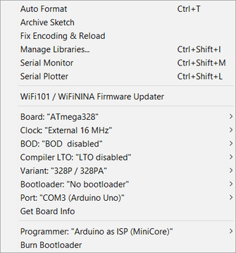
Before uploading the programing code, set the right tools. The Crystal I used is 16 Mhz.
-
To upload the code click on “Uploading Using Programmer” from “Sketch” tab.
Video
This video shows us how the project works. The ultrasound will read the height of the water in the aquarium. If the height of the water is less than the required rate, we will hear a sound from the speaker to alert, and “NO WATER :(” phrase will also appear on the LCD screen, which requires adding more water to the aquarium.
After adding the water, or when the height of the water is appropriate, it will move to the next step, which is spraying the plants from the aquarium water, or in other words, running the pump to spray the plants. The pump will turn on only when the humidity is less than 45% in the plant’s environment.
The third step is to read the light sensor. If the lighting that the plant is exposed to is insufficient, the light will turn on, and if it is sufficient, it will turn off.
Here it is evident that no matter how low the humidity of the plant’s surroundings is if the water level below normal.
Source Code
Main Setup and Main Loop
// Libraries Available
#include  <Relay.h>
#include  <HCSR04.h>
#include  <LiquidCrystal_I2C.h>

#include <MyRealTimeClock.h>

#include <SoftwareSerial.h>

SoftwareSerial mySerial(1, 0); // RX, TX

MyRealTimeClock myRTC(9, 8, 10); // Assign Digital Pins

// Pin Definitions
#define   LIGHT_SENSOR    A0
#define   WATER_TEMP      A1
#define   SOIL_SENSOR     A2
#define   HCSR_TRIGGER    3
#define   HCSR_ECHO       2
#define   GROW_LIGHTS     4
#define   WATER_PUMP      5
#define   SPEAKER         11

// Library Objects
Relay     _grown_lights(GROW_LIGHTS, true);
Relay     _S_Pump(WATER_PUMP, true);
LiquidCrystal_I2C lcd(0x27, 16, 2);
UltraSonicDistanceSensor distanceSensor(HCSR_TRIGGER, HCSR_ECHO);  // Trigger Pin, Echo Pin

//===========================================================================
//  Main Setup
//===========================================================================

void setup() {
  myRTC.setDS1302Time(00, 45, 12, 15 , 28, 07, 2020);
  pinMode(11, OUTPUT);
  mySerial.begin(9600);
  _grown_lights.begin();
  _grown_lights
  .turnOff();
  _S_Pump.begin();
  _S_Pump.turnOff();

  lcd.init();
  lcd.clear();
  lcd.backlight();

  LCD_PRINT("FABACADEMY", "2020");
  LCD_BLINK(3, 1500);
  LCD_PRINT("MIXOPONICS <3", "");
  LCD_BLINK(1, 3000);
  delay(100);
  lcd.clear();
}

//===========================================================================
//  Main Loop
//===========================================================================

void loop() {

  mySerial.print(myRTC.hours);

  // Making Sure The Water Will Be Less The 7 CM High
  while(readDistance(true) > 15) {
    LCD_PRINT("NO WATER :(", "");
    tone(SPEAKER, 255,250);
    delay(250);
    tone(SPEAKER, 0,250);
    delay(250);
  }

  // Turn Of The Tone
  noTone(SPEAKER);

  // Short Delay
  delay(2000);

  // Reading Water Temperature
  //if(readTemp(true) > 30) {
  //  _S_Pump.turnOn();   // To Cool The Water Through Moving It Into the Air
 // } else {
  //  _S_Pump.turnOff();  // No Need To Turn On The Pump Because The Water Temperature Is Good
 // }

  // Short Delay
  //delay(2000);

  // Reading Current Time Form RTC Module
    myRTC.updateTime();
    mySerial.print(myRTC.hours);
    mySerial.print("time is: ");
     // LCD_PRINT(myRTC.hours );
      //LCD_PRINT("time is :", String(myRTC.hours));
  //delay(2000);

  // If Time Is Between 6am and 6pm
   if (myRTC.hours >= 6 && myRTC.hours <=18){
    // Cheacking The Light
          mySerial.print("light on1: ");

    if(readLight(true) < 500) {
      mySerial.print("light on: ");
      _grown_lights.turnOn();
    } else {
      _grown_lights.turnOff();
    }
  }

  // Short Delay
  delay(250);

  // Make Sure The Soil Sensor Is Wet Enough
  while(1) {
    // Reading Soild Moisture
    int soil = readMoisture(true);

    // Checking The condition
    if(soil >= 30) {
      break;
    } else {
      _S_Pump.turnOn();
      mySerial.print("pump on ");
    }
  }
  // Turn Of The Pump
  _S_Pump.turnOff();

  // Short Delay
  delay(250);
}
LCD Code
//===========================================================================
//  Blink The LCD Back Light
//===========================================================================

  void LCD_BLINK(int Times, int Delay) {
    for(int i=0; i<Times; i++) {
      lcd.noBacklight();
      delay(Delay/2);
      lcd.backlight();
      delay(Delay/2);
    }
  }

//===========================================================================
//  Write On the LCD Screen
//===========================================================================

  void LCD_PRINT(String Line1, String Line2) {
    lcd.clear();
    lcd.setCursor((16-Line1.length())/2, 0);
    lcd.print(Line1);
    lcd.setCursor((16-Line2.length())/2, 1);
    lcd.print(Line2);
  }
Sensors Readings Code
//===========================================================================
//  Water Level Sensor
//===========================================================================

  double readDistance(bool display) {
    double temp = 0;

    for(int i=0; i<10; i++) {
      temp += distanceSensor.measureDistanceCm();
      delay(20);
    }

    temp/=10;

    if(display) LCD_PRINT("DISTANCE : CM", String(temp));
    return temp;
  }

//===========================================================================
//  Soil Moisture Sensor
//===========================================================================

  int readMoisture(bool display) {
    int temp = 0;

    for(int i=0; i<10; i++) {
      temp += map(analogRead(SOIL_SENSOR),550,0,0,100);
      delay(20);
    }

    temp/=10;

    if(display) LCD_PRINT("Moisture : %", String(temp));
    return temp;
  }

//===========================================================================
//  Natural Light Sensor
//===========================================================================

  int readLight(bool display) {
    int temp = 0;

    for(int i=0; i<10; i++) {
      temp += analogRead(LIGHT_SENSOR);
      delay(20);
    }

    temp/=10;


    if(display) LCD_PRINT("INTENSITY :", String(temp));
    return temp;
  }