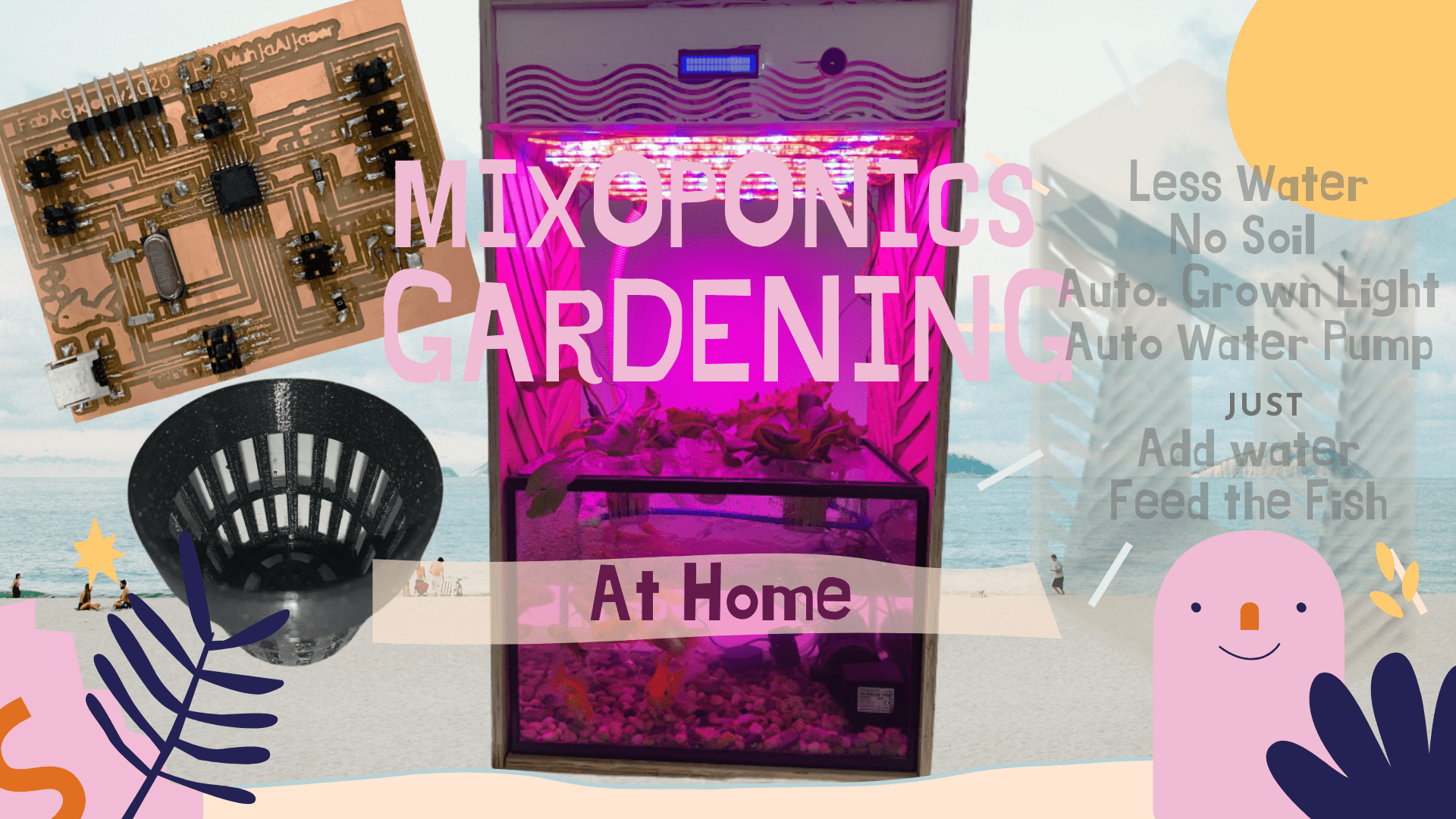
Final Project
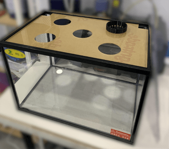
I will design a system for home-scale aquaponics, which is a fish tank (Aquaponics), where the plants supported at a distance from the surface of the water.
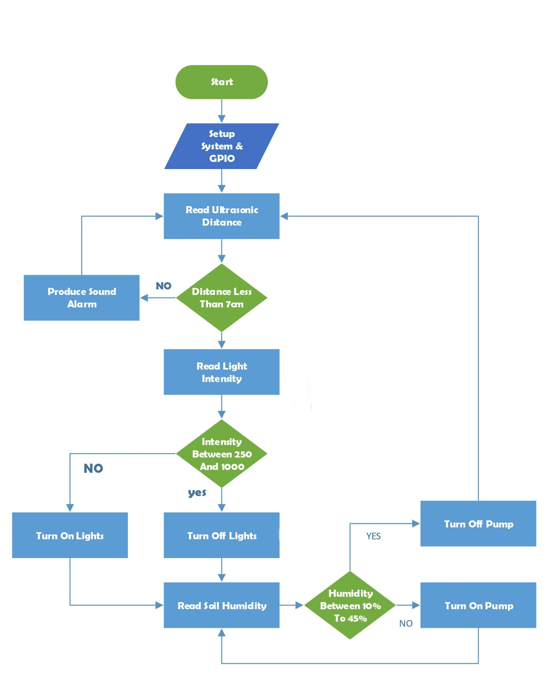
Flowchart Diagram
The first step in designing an electrical circuit is to define its inputs and outputs, that is, to determine the purpose of the design.
To make this easier, I draw a flowchart diagram of the system I wanted. Each sensor I have set has a purpose, every input will be attached with an output to build a complete system. This diagram shows how the system works according to the sequence, and that what I will translate by writing the code to program the electrical circuit.
Printed circuit board
Components
inputs
- Humidity of Soil
- Water Tempreture –> TMP36
- Water Level –> HC-SR04 Ultrasonic
- Light Sensor
Among the future plans I will use:
- ph sensor
- ammonia sensor
Outputs
- Lcd Screen (I2C)
- Relay for the Submersible pump
- Relay for the lights
Also, in each electrical circuit, these parts must be present in order for the programming process to take place as required:
- USB header
- Crystal
- ISP header
- FTDI header
- microcontroller
Microcontroller
The next step after specifying the inputs and outputs is to identify the microcontroller that can accommodate them. I had two options, either to choose “Atmega328P” or “Attiny84”.
I chose Atmega328P because it has enough pins. Also, I can reuse the same code for Arduino and there are loads of examples for it, but it’s difficult to solder, that’s my challenge. On the other hand, Attiny84
is easy to solder and design and mill, but it may not have enough pins for everything, and I cant reuse all the old code and there are fewer examples.
Importance of each Sensor
- Growth Medium Humidity
Larger fruiting plants need to be immersed more often than smaller plants, those that do not contain fruit or grow slowly. Most plants will do well if the growth bed is drenched three or four times a day. If the climate is hot and dry, drench it more frequently than if the weather is cold and humid.
As the moisture evaporates around the gravel, the relative humidity near the plants increases. Proper humidity helps plants increase photosynthesis for optimal growth, with optimum humidity in the water system ranging from 50-70%.
When plants grow in low humidity, the plant will face some difficulties in taking water to plant, To increase humidity, plants can be grouped close together. Also, high humidity may reduce the efficiency of plants to absorb water, and this can promote mold growth in wet areas.
Visit : - Best Humidity For Aquaponics
- How Often Do You Flood an Aquaponics Grow Bed?
-
Water temperature measurement
Monitoring and maintaining a consistent water temperature in the aquaponics system is particularly important for the health of the fish. Fish are considered poikilothermic which means that they are cold-blooded and their body temperature is not internally regulated. As a result, their internal body temperature is entirely dependent on the surrounding water temperature. If the water temperature is swinging and not consistent, fish eat typically declines and they can become more susceptible to illness.
The ideal water temperature is a variable that depends entirely on what fish species and what plants you are growing. Tilapia thrive in temperatures between 70-85 F, but most Aquaponic farmers keep their Tilapia tanks between 72-78 F (depending on the sub-species of Tilapia), which is a compromise between the fish temperature requirements and the plant requirements.
Despite plants need a steady supply of water, it will not respond well if submerged all the time. As a general rule warm freshwater fish and leafy crops such as lettuce and herbs will do the best, so if the temperature of your water is above 89 degrees plants will not be able to photosynthesize.
Visit : - Ecolife Conservation
- 7 rules-of-thumb to follow in aquaponics
- Aquaponics Water
- Aquaponics Water Temperature For Plants
-
Water Level
Check the water level, and add additional water to compensate for evaporation, as necessary. Determine fish tank volume from the stocking density rule; 1 pound fish per 5 – 7 gallons of fish tank volume or 5 kg per 20-26 liters. When your fish are young and small, reduce the number of plants in proportion to the size of the fish and their corresponding feed. Visit : - Aquaponic Gardening Rules of Thumb
-
Light Sensor
Light intensity influences the manufacture of plant food, stem length, leaf color, and flowering. Generally, plants grown in low light tend to be spindly with light green leaves, but plants that don’t have enough light will be weak, thin and leggy, or short, squat, and stunted. A similar plant grown in very bright light tends to be shorter, better branches, and have larger, dark green leaves. But, not all plants can tolerate the higher temperatures. If plants are getting heat stressed, showing burning or crispy leaves, then move the light higher, remove heat with proper venting and air exchange and encourage air movement with circulation fans. In most cases, plants receiving no outdoor light should be lit from 16 to 18 hours each day. If some additional light is received, 12 to 14 hours each day may be adequate. Lights should be used at the same time that plants receive window light. Using lights at the beginning or end of the day will not usually be as effective as using lights during daylight unless natural daylight is quite bright. Most plants should be located with the tips of the plants 6 to 12 inches from the light source. The intensity of light drops rapidly as the distance from the light bulbs or tubes increases. Grow lights diminish in light value over time, except LEDs. Even if you can see the light, the light quality can be reduced enough, that the plants can no longer absorb it, and therefore the lights are consuming electricity without providing much photosynthetic value to the plant. Plants that can adapt to interior settings usually are divided into three general categories: those suitable for low, medium, and high light intensities.- Low-light plants
Plants referred to as low light intensity plants generally should receive between 50 and 250 foot-candles. Under artificial light, a few plants in this group can be maintained at as little as 10 foot-candles. Low-light plants should receive between 10 and 15 watts of fluorescent light per square foot of growing space. A single fluorescent tube such as a 2-foot 20-watt tube or a 4-foot 40-watt tube without any other light provides only enough light for plants in this category. - Medium-light plants
Medium light intensity plants prefer 250 to 1,000 foot-candles. Best growth occurs above 750 foot-candles unless plants also receive extended periods of direct sunlight. Give them artificial light in the 500 to 1,000 foot-candle range, or 15 or more watts per square foot of growing area. Although plants in this group can be held in the 250 to 500 foot-candle range, growth is best with more light. A fixture containing two fluorescent tubes is sufficient for plants in the low- to medium-light range. Adjustments in the number of tubes used may be made if you regulate the distance between the tubes and plants. - High-light plants
Plants that require high light intensity generally are less satisfactory for growing under artificial lights in the home. However, if you want to try, use special high-intensity lamps. These plants need at least 1,000 foot-candles, or 20 watts per square foot of growing area, but should have higher intensities for best growth and flowering. Fixtures containing three to four fluorescent tubes are necessary for plants requiring high light intensity.
Visit :
- Low-light plants
- Lighting Indoor Houseplants
- Mimicking the Sun – Indoor Grow Lights
Designing PCB
The design of the Final Project circuit I used EasyEDA software, to download it click here.
I made three attempts to design the circuit, the first two were unsuccessful because of mistakes that I benefited from and I will avoid them happening next time.
The First Attempt
Problem 1
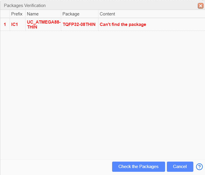
After I choose the components and I want to “Convert to PCB”; This window opens to me which says that “Can’t find the package” for my ATmega88.
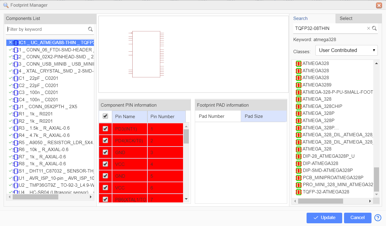
After I clicked on the “Check the Package” option in the previous window, this window appeared for me, which asked me to choose an alternative to my ATmega. I chose the first option, and then “Update”, but this didn’t solve the problem.
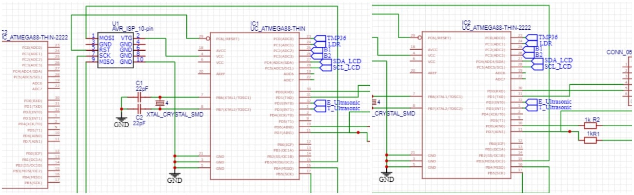
I added the same component from another library, with its image diagram, I exchange it from “UC_ARMEGA88 ThIN” to “UC_ARMEGA88 ThIN 2222” as I name it; The problem was solved. The problem was that the micro image did not exist.
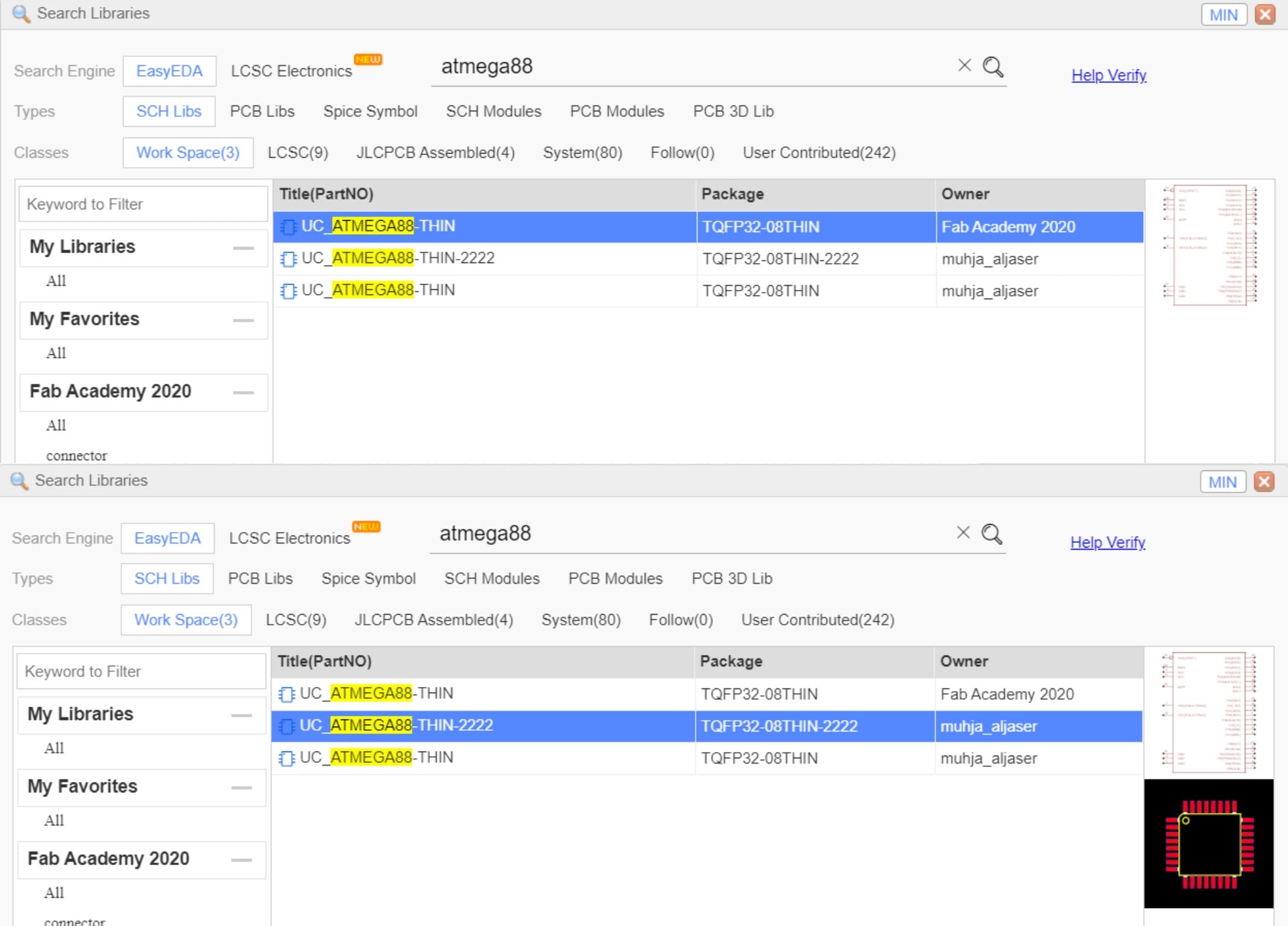 I deleted the old micro and put the new micro in its place without changing the location of any part.
Problem 2
These are the “design rule” I used that I didn’t set it from the beginning of the design.
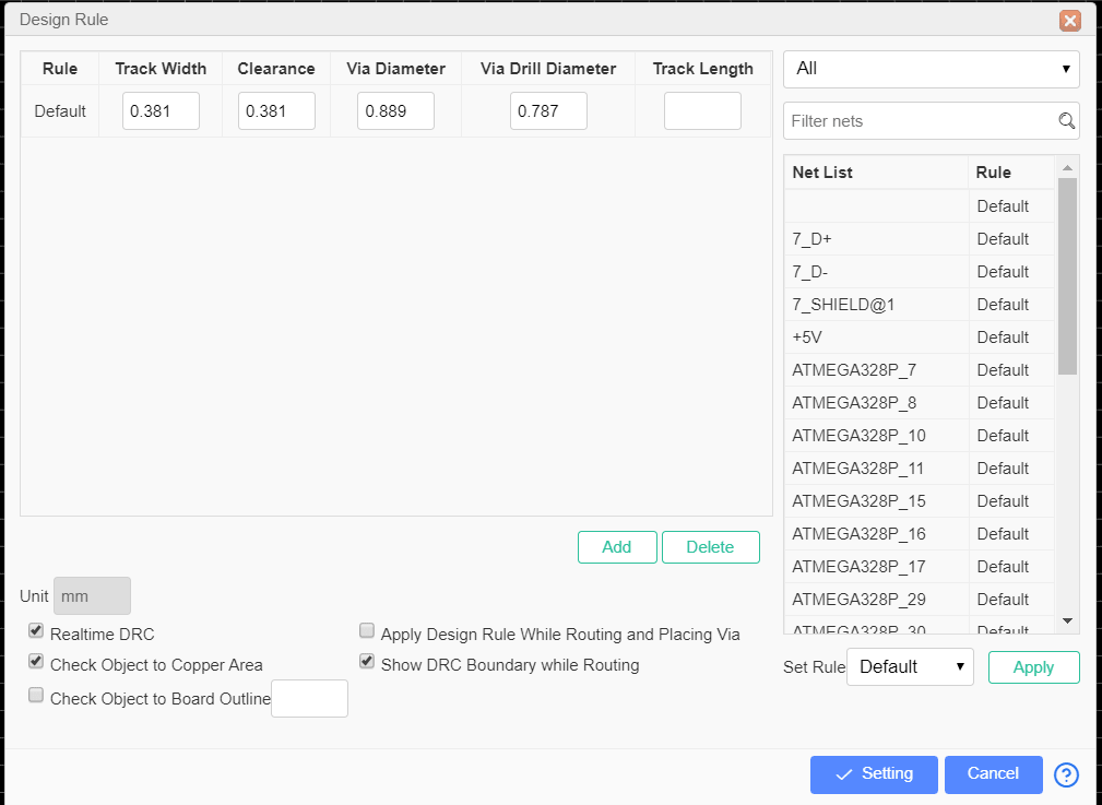
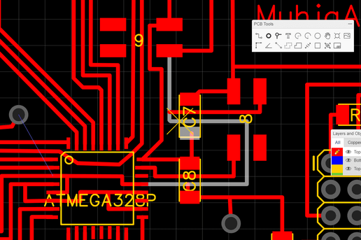
Resulting from design rule change, many ” DRC errors” can be checked by “Design Manager”. Appears in DCR errors “Track width” and “Clearance”. When you click on one of the errors it shows you the error location, which you have to adjust, after that click on the “Refresh arrow”, the number of the errors in the brackets decreases. You have to make this number zero. The “Track width” indicates that the width of the line is not equal to the width set in the design role.
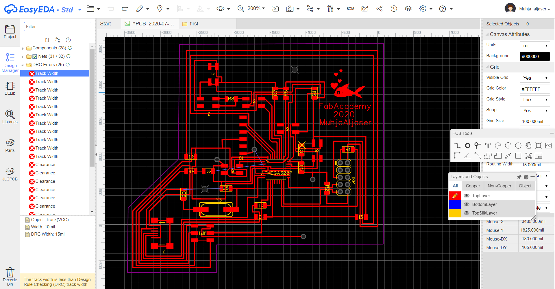 As for the Clarence, it indicates that there are traces that are close together; This can cause it not to be milled correctly.
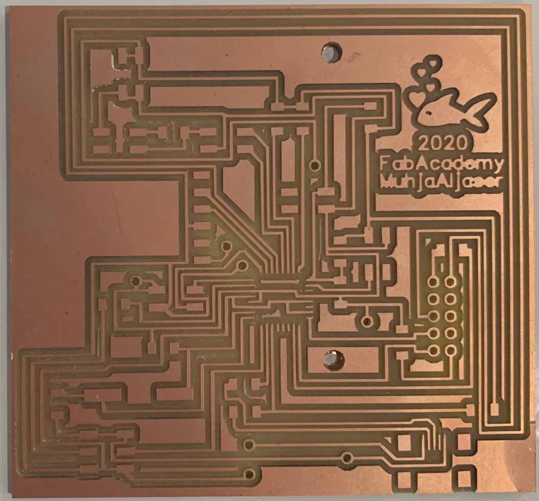
The Final PCB
These are two pictures of the PCB schematic and for the connection.
Exporting the PCB
The step before milling is to export the PCB.
- Top Layer > Convert the multi-layer holes to the top layer, and export it without Top silk layer)
 - Holes > Reduce the size of the holes, because this hole is the one that the machine will mill. I didn’t change the size of the holes in the previous step, in the “Top layer” just to facilitate soldering.
 - BoardOutLine > Do not mill the board outline before the milling the holes so that the PCB does not move when milling the holes.
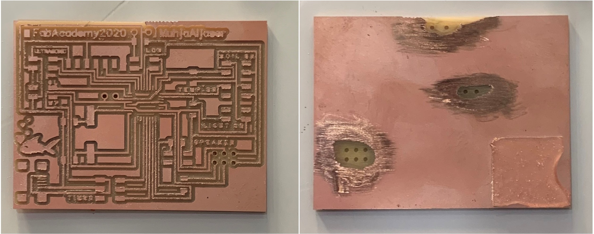
After Milling

Problem 4
After I used the multimeter to check the conductivity between the traces, I saw that the VCC is the same as the GND.
 The problem was that when I connected the wires behind the board I connected them to each other because the back layer is conductive as well. So I peeled off the position of the holes where the wire will be exposed. This was not the only problem causing.
 After being unable to find the problem in my soldering method, I followed the path of VCC and GND to see where they could meet, until I knew that the machine did not mill the board at a place where they were connected.
 I manually peeled this position to solve this problem.
Problem 5
This was the last problem I faced that I had to redesign the board, which is that when I wanted to solder the USB I realized that I had not positioned it correctly. Because when I want to plug the USB cable, I will not be able to do that, because the entrance will be on the inside of the board and not on the outside as I thought, where I will not be able due to the small space.
The Second Attempt
In my second attempt to design the board, I did not change anything except that I removed the jumper wires that I do not need and added what I need after putting the USB in its correct position.
This is how the board looked after the design was completed.
This is how after milling, I checked that no wires were not milled by the machine.
I did not have four headers, and the six headers could have been cut off.
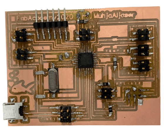
 This is how the board after I finished soldering.
 The first thing I did after the milling was to peel the position of the holes from the back.
Programing
To set Arduino UNO in ISP mode, connect the Arduino UNO to the PC. Open Arduino IDE and open the ArduinoISP example file (File -> Examples -> ArduinoISP) and upload it.
This is the ISP 10 headers top view.

I connected the board ISP with Arduino UNO
UNO 5V –> VCC
UNO GND –> GND
UNO Pin 13 –> SCK
UNO Pin 12 –> MISO
UNO Pin 11 –> MOSI
UNO Pin 10 –> RESET
There is no result of this connection, no code can be uploaded on it.
Problem 1
I realized that I have to put a resistor between VCC and the RESET in the ISP, so that not all the pins be RESET.
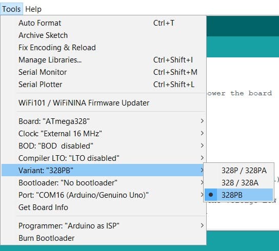
Problem 2
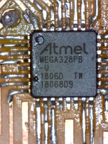
The main problem seemed to be that I soldered “ATmega328PB” instead of “ATmega328P”. Here I learned that the single letter makes a big difference in electronics.
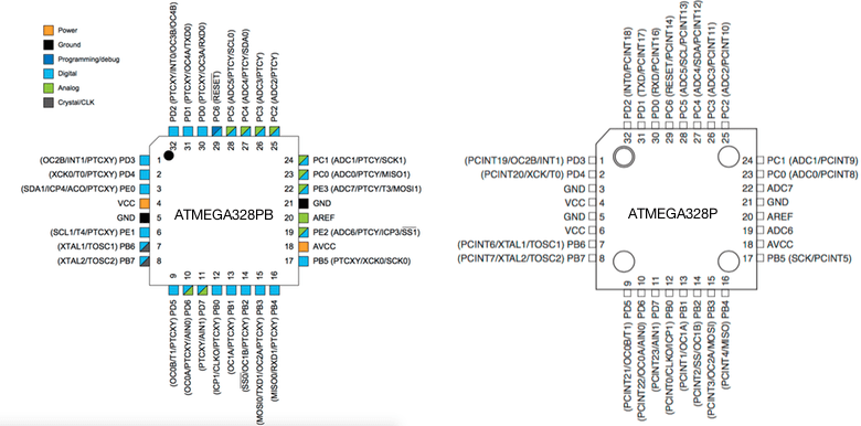
This is the pinout for each of them, it seems that the difference is not great.
 To start programming “ATmega328PB”, I followed the steps on MiniCore site, “How to install” >> “Boards Manager Installation”.
- Using Arduino IDE Open the “File” >> “Preferences” and enter the following URL in Additional Boards Manager URLs:
https://mcudude.github.io/MiniCore/package_MCUdude_MiniCore_index.json
- Open “Tools” >> “Board” >> “Boards Manager”. Search for “MiniCore” and install it.
- Make sure the latest version is installed for “Arduino AVR boards” from the “Boards Manager”.
Here I could compile the code on the board.
 To write the code correctly, I must know the Arduino pins for the microcontroller.
 I was putting every component and upload the code on it separately. Here it shows that the sound is interrupted when the distance measured by the ultrasonic is less than 7cm.
After that, I tried, again and again, to upload the code to the board but there was no result.

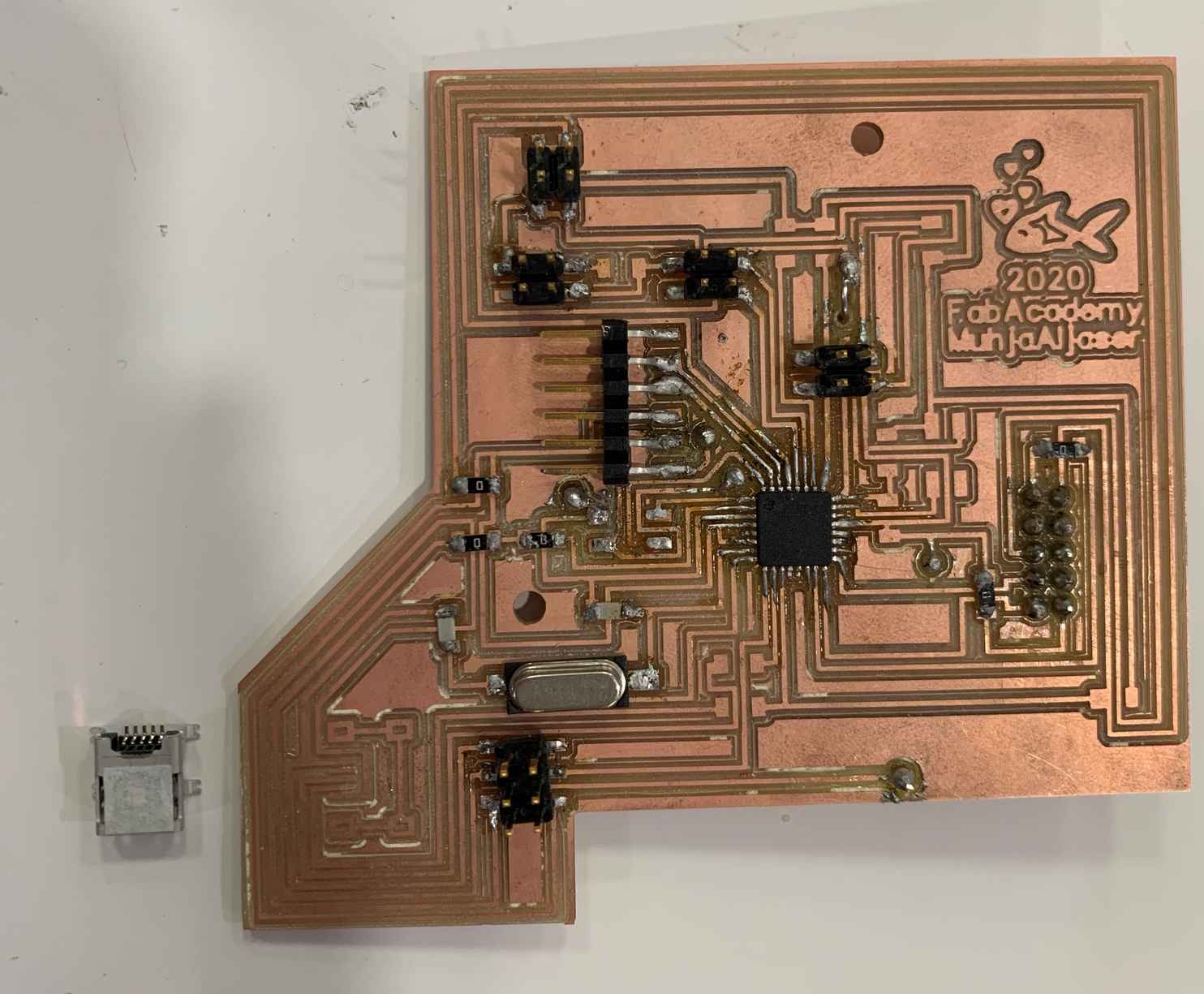
The Third and the Final Attempt
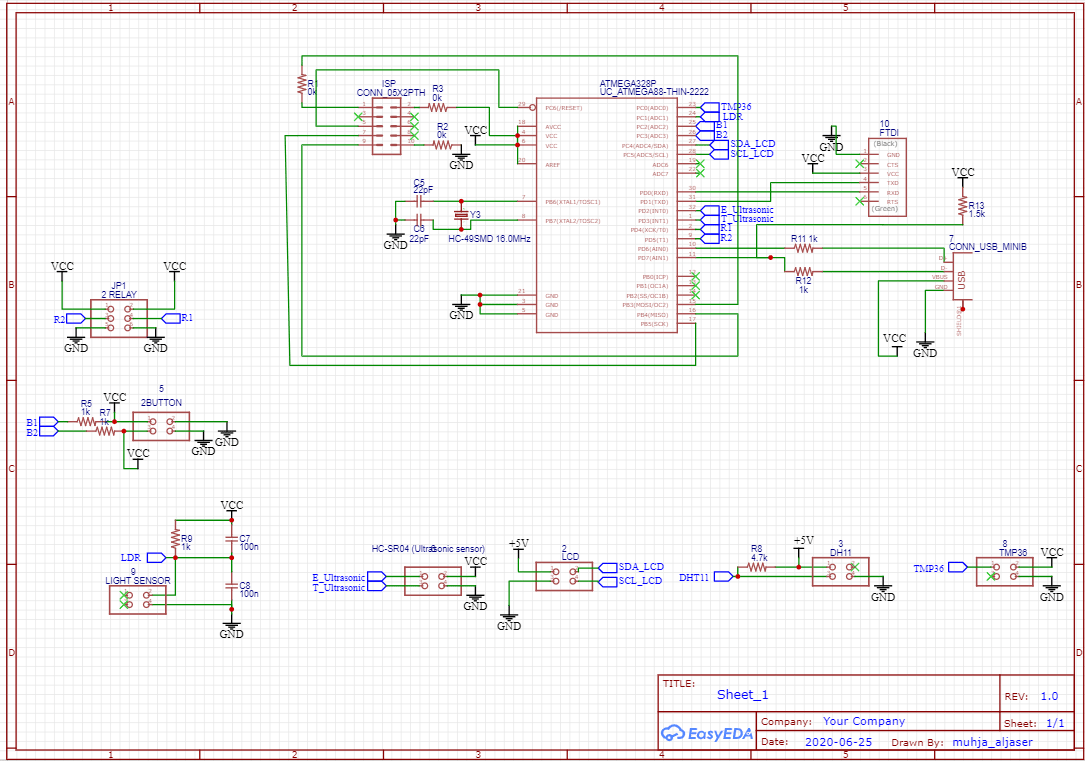
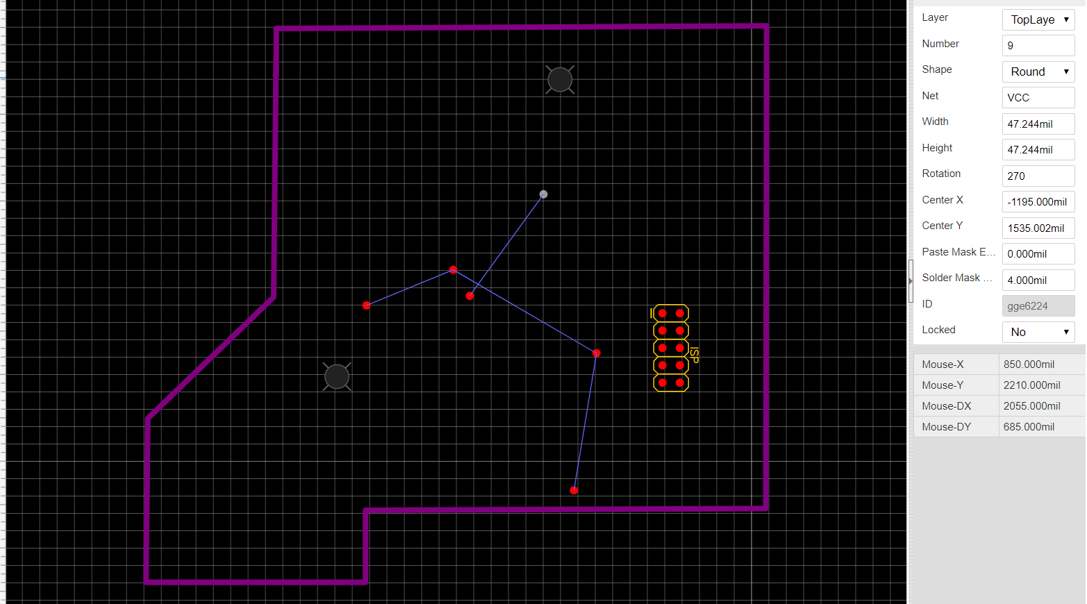
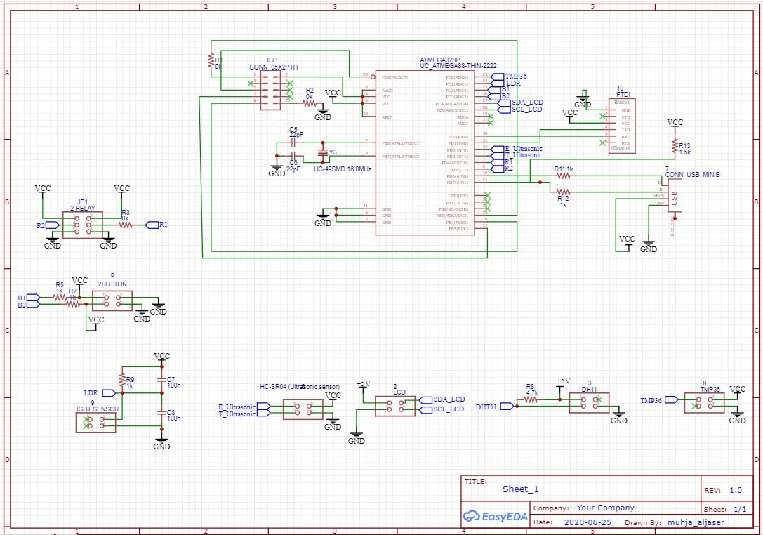
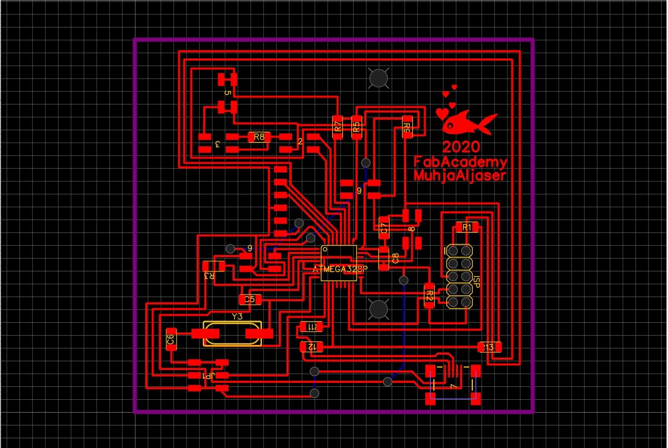
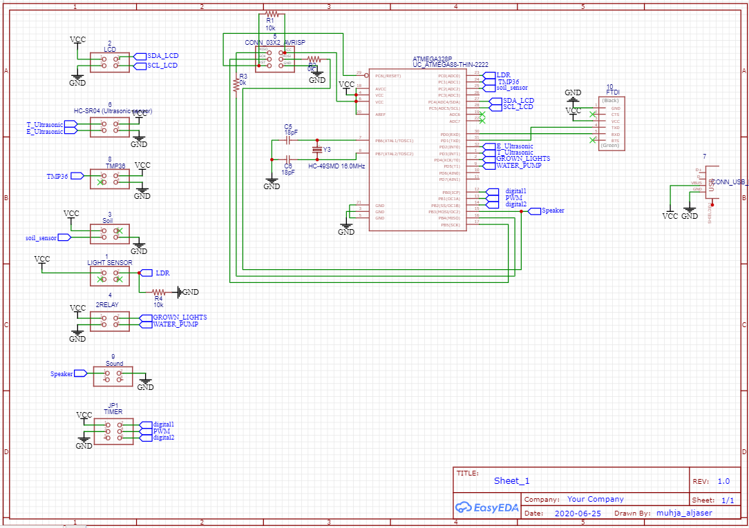
This is schematic and I made some adjustments to it by removing and adding some inputs and outputs headers.
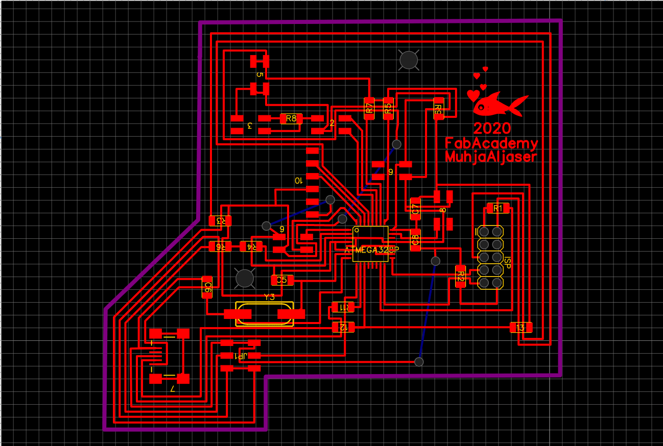
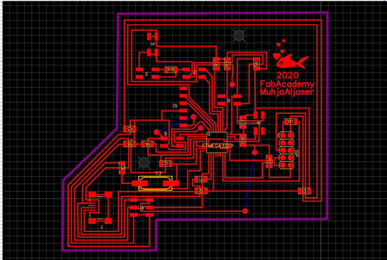
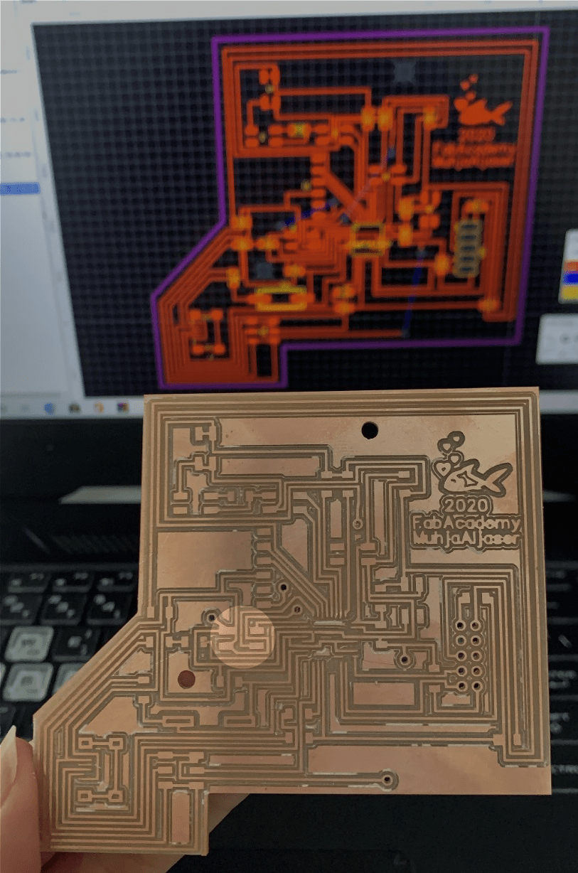
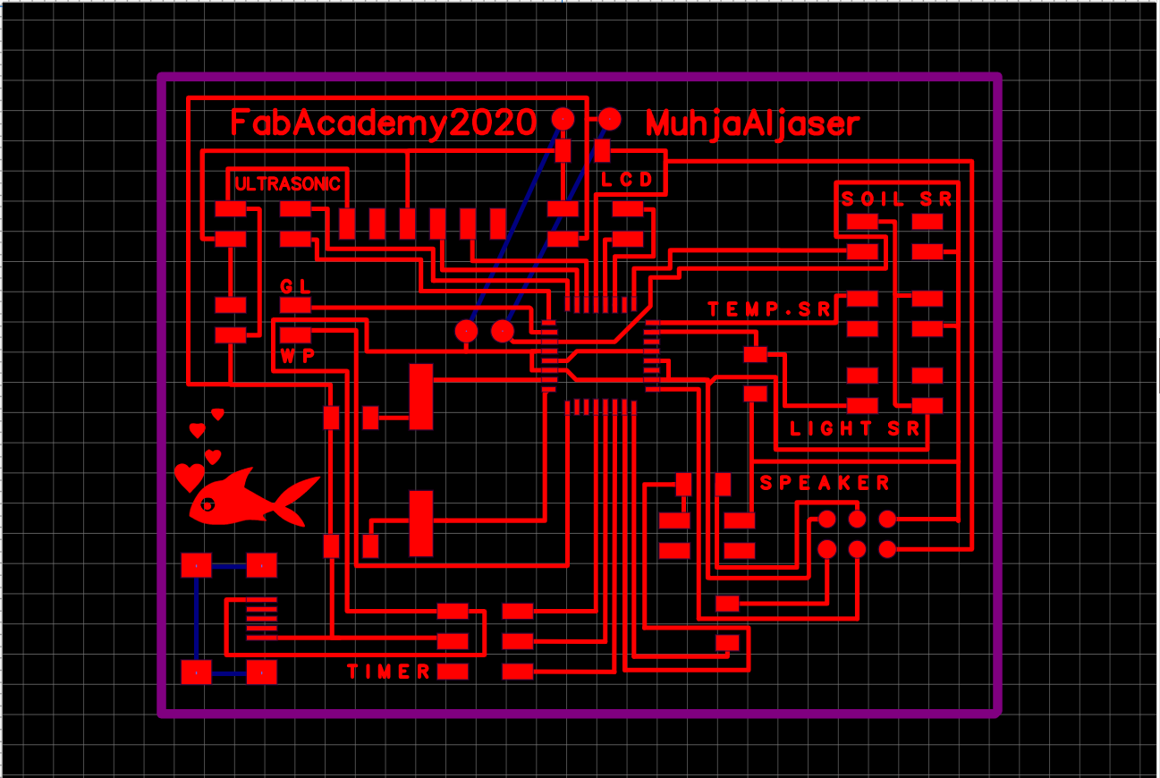
 This is how the PCB looks.
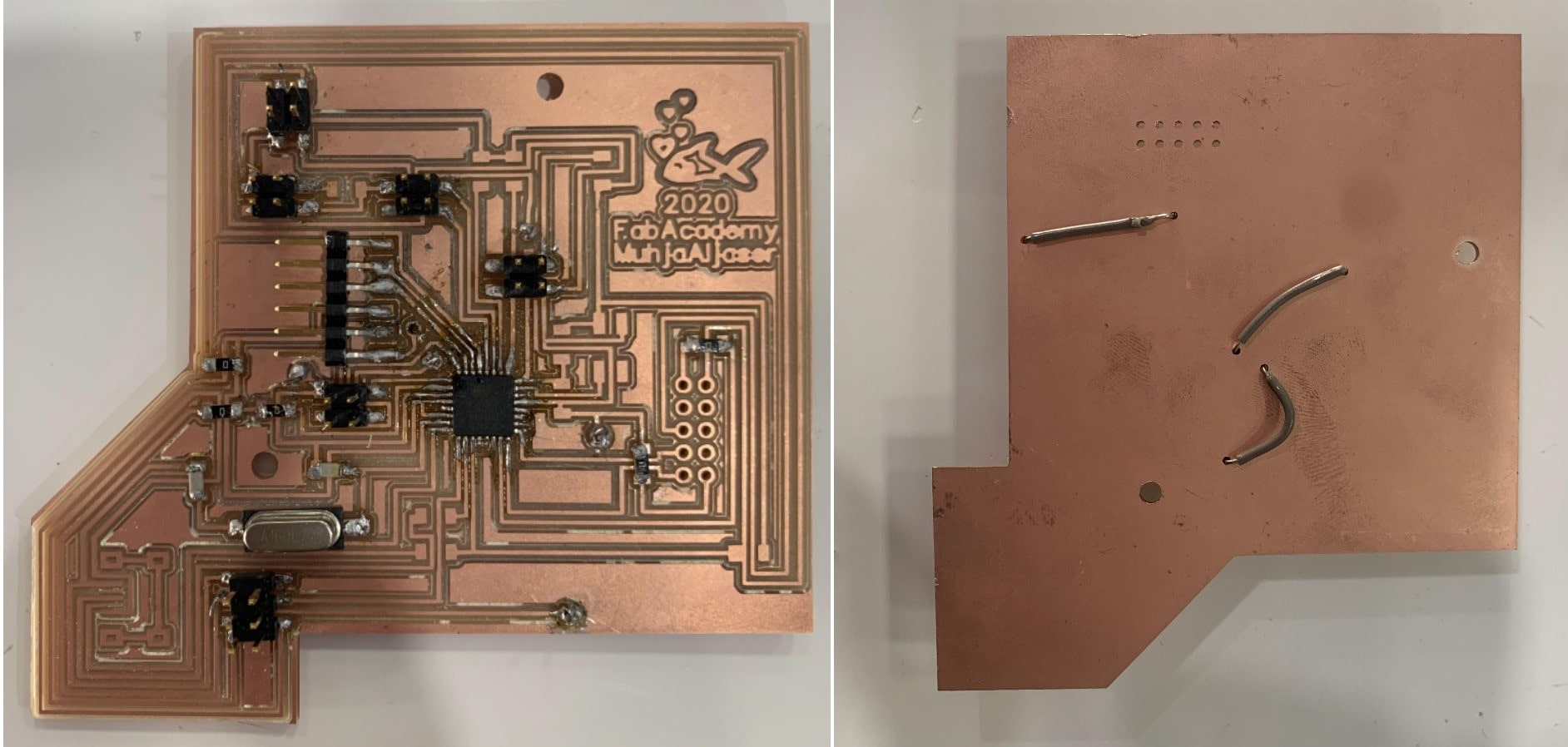
 This is how the PCB looks after milling. And of course, I don’t forget to peel off the back layer.
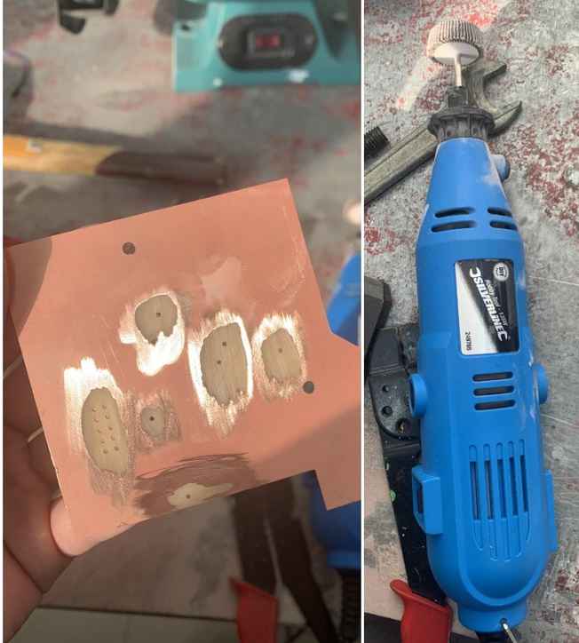
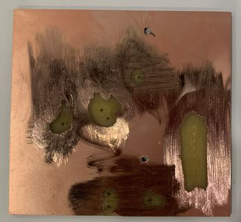
 Before I mill the holes on the board, I look at it to make sure if it needs to be milled again. There are two tracks the machine didn’t mill it, but no problem I will peel them manually. It became clear to me after that that I didn’t check the “Clearance” for them.
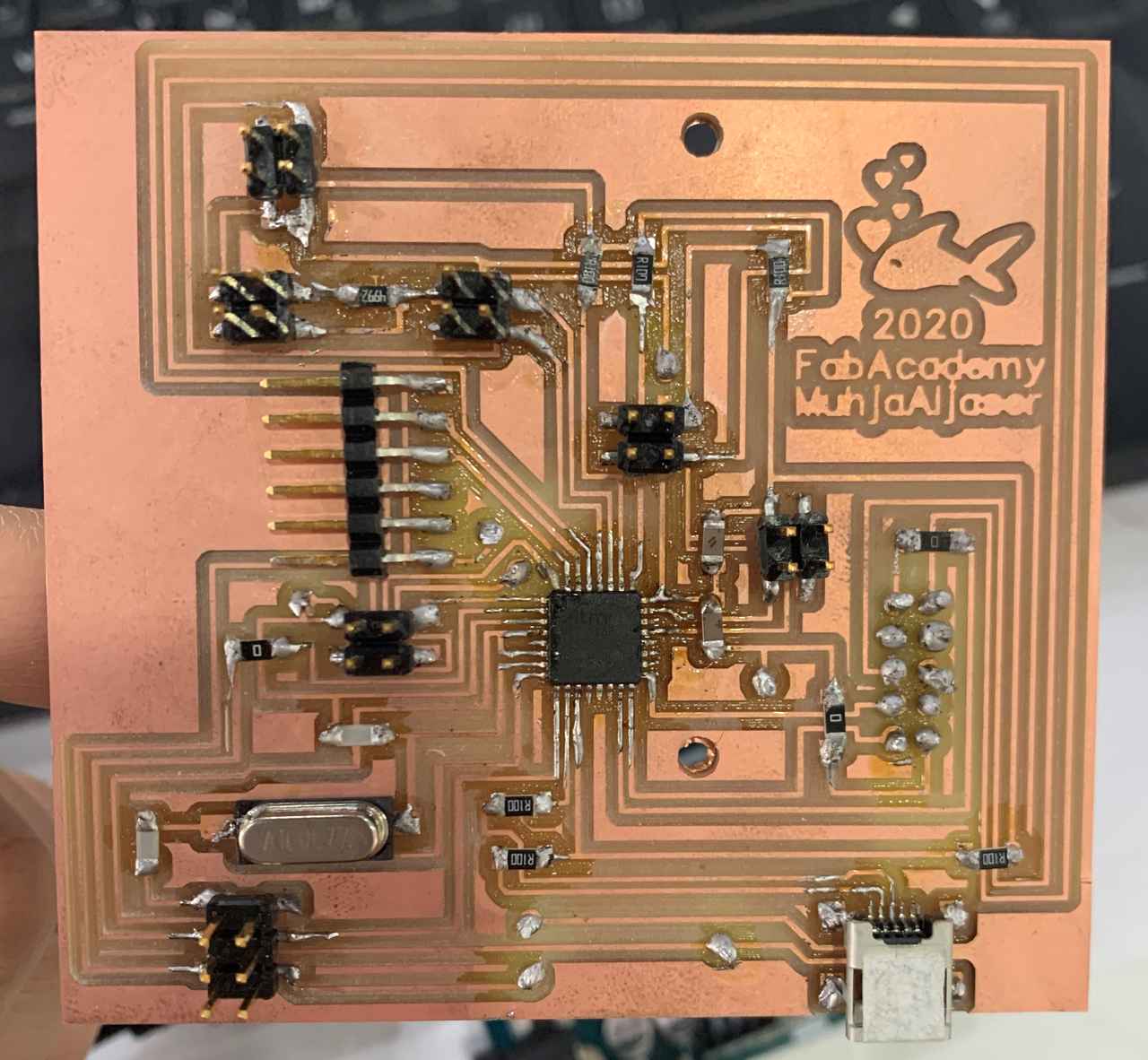
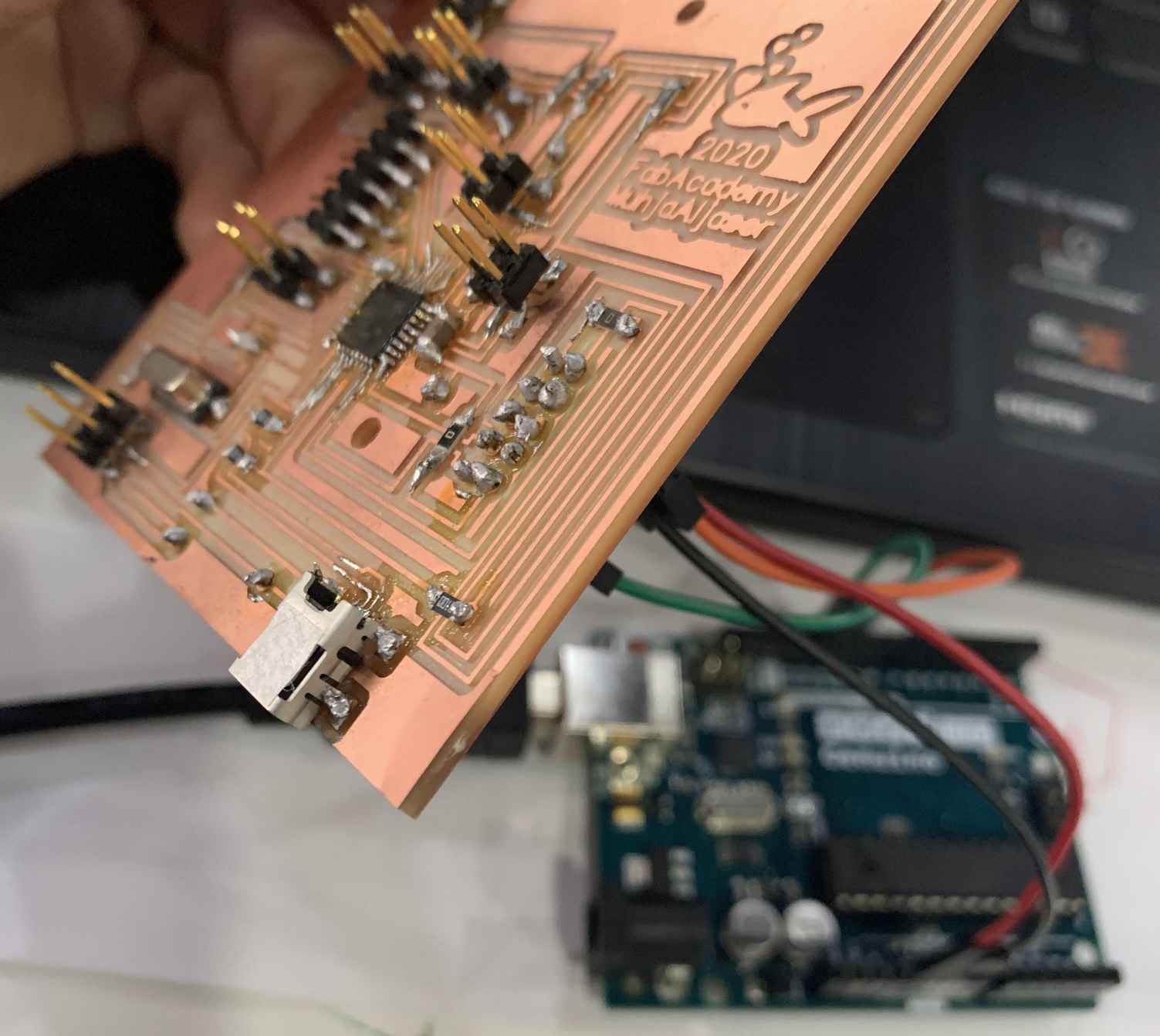
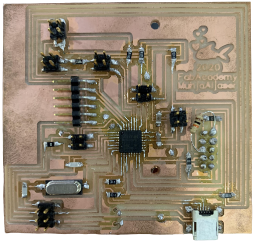
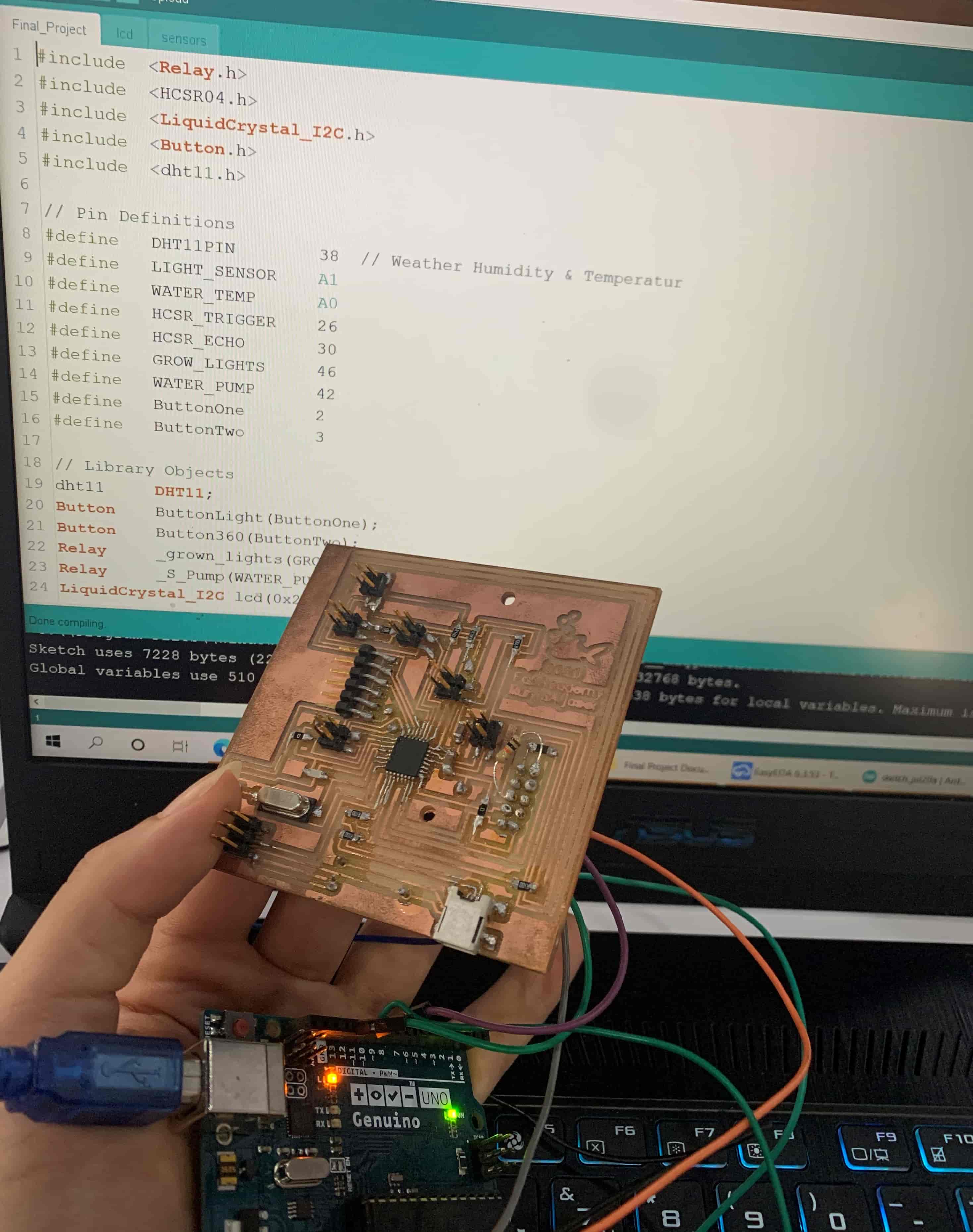
![]() This is how the PCB looks after solderig.
This is how the PCB looks after solderig.
Files
- Final Project Schematic sch.
- Final Project PCB json.
- PCB Top Layer svg.
- PCB Holes svg.
- PCB Boarder svg.
Programing the PCB
As for my PCB, I will program it using the Arduino UNO as a programmer following the same previous steps:
Connection and Programming
-
I connected the Arduino pins to the ISP header on the PCB via jumpers:
- Arduino Pin 13 - - SCK
- Arduino Pin 12 - - MISO
- Arduino Pin 11 - - MOSI
- Arduino Pin 10 - - RESET
- Arduino 5V - - VCC
- Arduino Ground - - GND
-
Set up the Arduino by uploading the “ArduinoISP” code to the Arduino, and that’s from selecting “File” >> “Examples” >> “ArduinoISP”. The Arduino now is an AVR ISP.
-
This is a step for us to be able to define ِAttiny44 in “Tools” for the Arduino. Copy this URL:
https://mcudude.github.io/MiniCore/package_MCUdude_MiniCore_index.json
Go to “File” > “Preferences”, and paste the URL in “Additional Boards Manager URLs” and click “Ok”.
-
Click “Tools” > “Board” > “Board Manager”, search for “minicore” and install it.
-
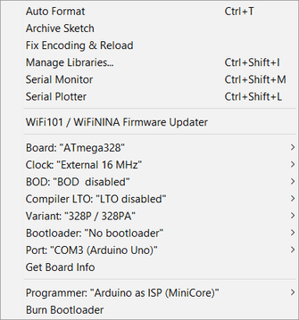
Before uploading the programing code, set the right tools. The Crystal I used is 16 Mhz.
-
To upload the code click on “Uploading Using Programmer” from “Sketch” tab.
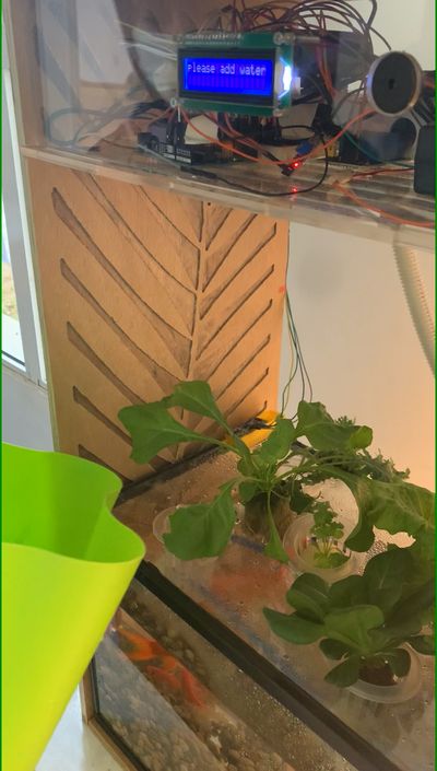
Video This video shows us how the project works. The ultrasound will read the height of the water in the aquarium. If the height of the water is less than the required rate, we will hear a sound from the speaker to alert, and “NO WATER :(” phrase will also appear on the LCD screen, which requires adding more water to the aquarium.
After adding the water, or when the height of the water is appropriate, it will move to the next step, which is spraying the plants from the aquarium water, or in other words, running the pump to spray the plants. The pump will turn on only when the humidity is less than 45% in the plant’s environment.
The third step is to read the light sensor. If the lighting that the plant is exposed to is insufficient, the light will turn on, and if it is sufficient, it will turn off.
Here it is evident that no matter how low the humidity of the plant’s surroundings is if the water level below normal.
Source Code
Main Setup and Main Loop
// Libraries Available
#include  <Relay.h>
#include  <HCSR04.h>
#include  <LiquidCrystal_I2C.h>

#include <MyRealTimeClock.h>

#include <SoftwareSerial.h>

SoftwareSerial mySerial(1, 0); // RX, TX

MyRealTimeClock myRTC(9, 8, 10); // Assign Digital Pins

// Pin Definitions
#define   LIGHT_SENSOR    A0
#define   WATER_TEMP      A1
#define   SOIL_SENSOR     A2
#define   HCSR_TRIGGER    3
#define   HCSR_ECHO       2
#define   GROW_LIGHTS     4
#define   WATER_PUMP      5
#define   SPEAKER         11

// Library Objects
Relay     _grown_lights(GROW_LIGHTS, true);
Relay     _S_Pump(WATER_PUMP, true);
LiquidCrystal_I2C lcd(0x27, 16, 2);
UltraSonicDistanceSensor distanceSensor(HCSR_TRIGGER, HCSR_ECHO);  // Trigger Pin, Echo Pin

//===========================================================================
//  Main Setup
//===========================================================================

void setup() {
  myRTC.setDS1302Time(00, 45, 12, 15 , 28, 07, 2020);
  pinMode(11, OUTPUT);
  mySerial.begin(9600);
  _grown_lights.begin();
  _grown_lights
  .turnOff();
  _S_Pump.begin();
  _S_Pump.turnOff();

  lcd.init();
  lcd.clear();
  lcd.backlight();

  LCD_PRINT("FABACADEMY", "2020");
  LCD_BLINK(3, 1500);
  LCD_PRINT("MIXOPONICS <3", "");
  LCD_BLINK(1, 3000);
  delay(100);
  lcd.clear();
}

//===========================================================================
//  Main Loop
//===========================================================================

void loop() {

  mySerial.print(myRTC.hours);

  // Making Sure The Water Will Be Less The 7 CM High
  while(readDistance(true) > 15) {
    LCD_PRINT("NO WATER :(", "");
    tone(SPEAKER, 255,250);
    delay(250);
    tone(SPEAKER, 0,250);
    delay(250);
  }

  // Turn Of The Tone
  noTone(SPEAKER);

  // Short Delay
  delay(2000);

  // Reading Water Temperature
  //if(readTemp(true) > 30) {
  //  _S_Pump.turnOn();   // To Cool The Water Through Moving It Into the Air
 // } else {
  //  _S_Pump.turnOff();  // No Need To Turn On The Pump Because The Water Temperature Is Good
 // }

  // Short Delay
  //delay(2000);

  // Reading Current Time Form RTC Module
    myRTC.updateTime();
    mySerial.print(myRTC.hours);
    mySerial.print("time is: ");
     // LCD_PRINT(myRTC.hours );
      //LCD_PRINT("time is :", String(myRTC.hours));
  //delay(2000);

  // If Time Is Between 6am and 6pm
   if (myRTC.hours >= 6 && myRTC.hours <=18){
    // Cheacking The Light
          mySerial.print("light on1: ");

    if(readLight(true) < 500) {
      mySerial.print("light on: ");
      _grown_lights.turnOn();
    } else {
      _grown_lights.turnOff();
    }
  }

  // Short Delay
  delay(250);

  // Make Sure The Soil Sensor Is Wet Enough
  while(1) {
    // Reading Soild Moisture
    int soil = readMoisture(true);

    // Checking The condition
    if(soil >= 30) {
      break;
    } else {
      _S_Pump.turnOn();
      mySerial.print("pump on ");
    }
  }
  // Turn Of The Pump
  _S_Pump.turnOff();

  // Short Delay
  delay(250);
}
LCD Code
//===========================================================================
//  Blink The LCD Back Light
//===========================================================================

  void LCD_BLINK(int Times, int Delay) {
    for(int i=0; i<Times; i++) {
      lcd.noBacklight();
      delay(Delay/2);
      lcd.backlight();
      delay(Delay/2);
    }
  }

//===========================================================================
//  Write On the LCD Screen
//===========================================================================

  void LCD_PRINT(String Line1, String Line2) {
    lcd.clear();
    lcd.setCursor((16-Line1.length())/2, 0);
    lcd.print(Line1);
    lcd.setCursor((16-Line2.length())/2, 1);
    lcd.print(Line2);
  }
Sensors Readings Code
//===========================================================================
//  Water Level Sensor
//===========================================================================

  double readDistance(bool display) {
    double temp = 0;

    for(int i=0; i<10; i++) {
      temp += distanceSensor.measureDistanceCm();
      delay(20);
    }

    temp/=10;

    if(display) LCD_PRINT("DISTANCE : CM", String(temp));
    return temp;
  }

//===========================================================================
//  Soil Moisture Sensor
//===========================================================================

  int readMoisture(bool display) {
    int temp = 0;

    for(int i=0; i<10; i++) {
      temp += map(analogRead(SOIL_SENSOR),550,0,0,100);
      delay(20);
    }

    temp/=10;

    if(display) LCD_PRINT("Moisture : %", String(temp));
    return temp;
  }

//===========================================================================
//  Natural Light Sensor
//===========================================================================

  int readLight(bool display) {
    int temp = 0;

    for(int i=0; i<10; i++) {
      temp += analogRead(LIGHT_SENSOR);
      delay(20);
    }

    temp/=10;


    if(display) LCD_PRINT("INTENSITY :", String(temp));
    return temp;
  }
Files
Useful Link
LCD
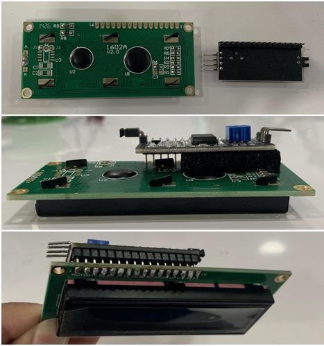
To facilitate the connection of the LCD, I welded the LCD piece to I2C driver. So instead of connecting sixteen pins, I will only connect four pins, for that I put four headers on the circuit board.
Output Devices
In my project, I used three output devices that will receive information from the input sensors and output it into its function to operate the system.
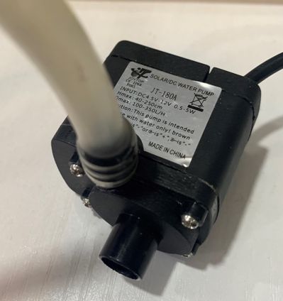
1. Submersible pump; This is the pump I used, where there is one hole in which the water comes in from the aquarium, and the other to water the plants.
2. Speaker “PKM22EP-20”
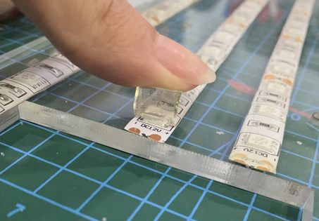
3. Grown Lights; The one I used is as a long strip, as shown in the image.
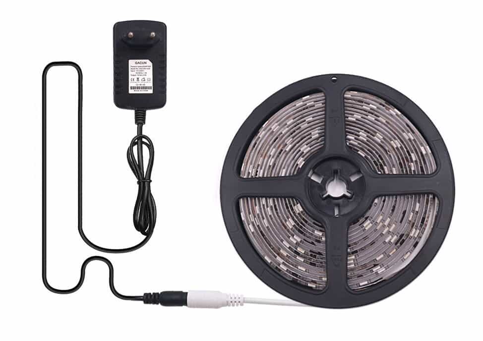
This light tape can be cut from where the scissors mark is.
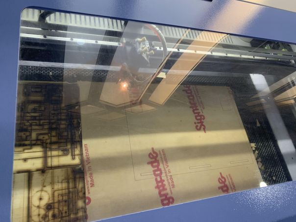
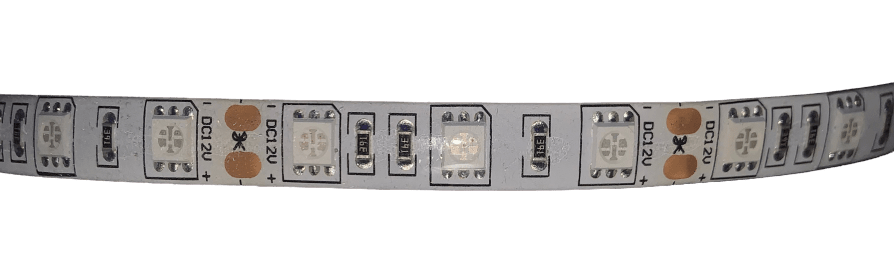 I removed the paper behind the tape and stuck it on the acrylic board that I cut with a laser cutter.
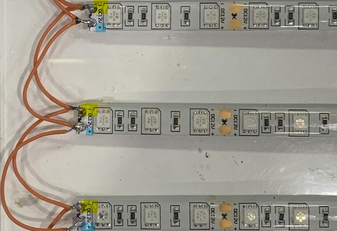
 Then, to connect the strips I lifted a portion of the transparent film off the copper and cut it.
I welded these pieces together in series from the copper spots, there are positive and negative signs on the white tape, where I connected the positive sign to the positive sign, and the negative sign to the negative sign, as shown in the picture.
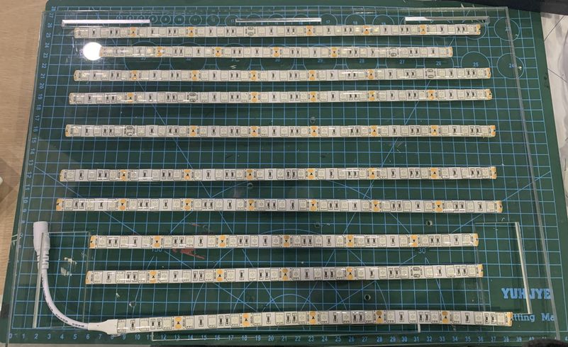
 This is the final form of welding.
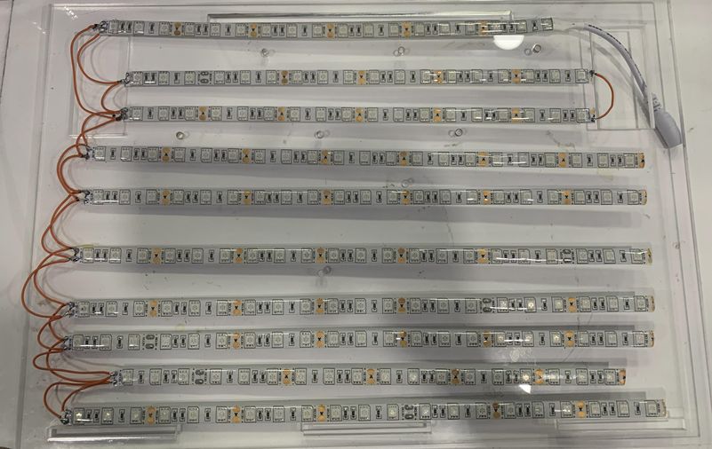 After I made sure that I connected the electrodes correctly to each other, I connected the electricity to the tape, and now it is fully lit.
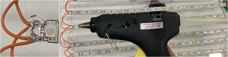
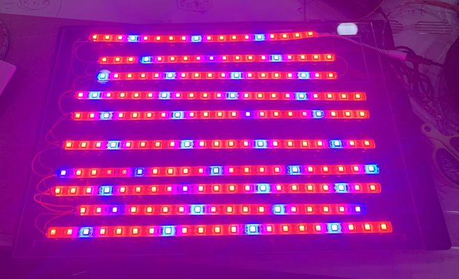 After the entire strip had lit up, I applied the glue to the soldering spots with the glue gun. This way I finished connecting the pieces of the grow light strip.
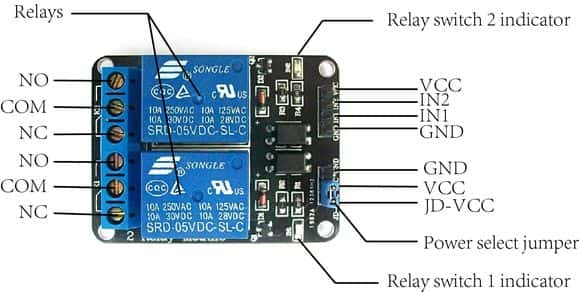
Two Channel Relay
Both of the Submersible pump and the Grown Lights are controlled from two relays. A relay is an electrically operated switch.
Pinout
The two channel relay module could be considered like a series switches; Two normally Open (NO), two normally closed (NC) and two common Pins (COM).
It has four pin header for connecting power, ground, and for controlling the two relays. There are two LEDs to indicate when relays are on.
Connection
I will use two “Power Outlet box”, each with one plug and a switch. The switch provided on the power outlet box can be manually used to turn ON or OFF the appliance plugged into the socket.
I stuck the two boxes to the inside of the acrylic board. I opened them to connect them to the relay module.
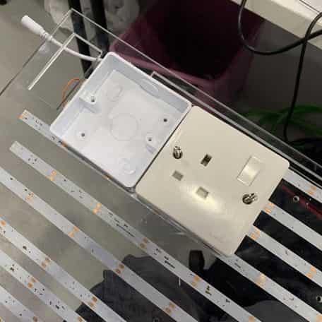
Both the boxes and relays will be connected by three colors of wire. This is the wire color code:
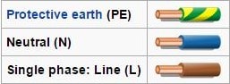
First, connect the “neutral wire” from the supply to the neutral connector on the socket.
The second terminal of the switch (top terminal) is connected to the Line (Hot) wire from the supply and also to the COMM (Common) terminal of the Relay.
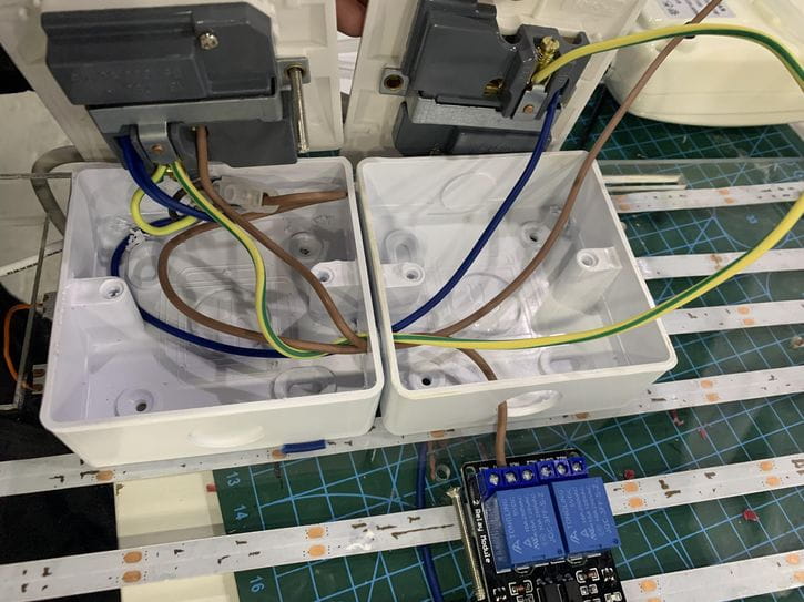
Connect the other connector on the socket to one end of the switch (bottom terminal) and also to the NO (Normally Open) contact of the Relay.
Connect the “Protective Earth” and “Natural” wires from the first socket to the other socket. Do that for the “Line” wire.
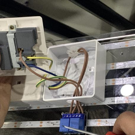
CAUTION: BE VERY CAREFUL WHEN CONNECTING WIRES, AND PAY ATTENTION TO THE COLOR CODE OF THE MANUFACTURER.
The VCC and GND pins for the relay module are given from the PCB, IN1, and IN2 connected to the PCB headers also, which will be triggered by the PCB with the help of the sensors.
When the intensity of the light falling on the LDR increases, the relay will be deactivated and appliance will be turned OFF. For demonstration purpose, we have connected a 27 Watt CFL light to the power outlet.
Arduino
When I failed to create the second circuit, I decided to start programming using the Arduino first. I think it is the correct way to start making any circuits because it reveals to us the deficiency and needs that we may not have noticed when drawing up the plan.
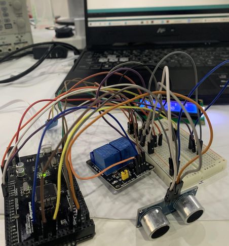
Here was my start in uploading the code on the LCD.
Testing LCD from Muhja Aljaser on Vimeo.
As for here, my attempt was to measure the water temperature in the fish tank using TMP36, due to the effect of water temperature on fish and plants. Where I connected the temperature sensor to the Arduino and put it in a box so that the water could not reach it, put it in hot water, and then display the values on the LCD screen.
I do not think that using this non-waterproof sensor is practical, because after a while from putting it in the tank, the water leak into it when spraying the plant. I recommend using the water temperature sensor, DS18B20 for example.
TMP36 in Water from Muhja Aljaser on Vimeo.
Materials
Here, I’ll show you what I did in the previous articles to the final project, to build the “Mixoponics Gardening”.
CNC 3D Model
Final Project CNC
I used this Tutorial in my design CNC Router with Fusion 360, Bookshelf Tutorial, I will design chips as joints using the parameters.
- At first I chose the thickness for wood as “18mm”, but I changed my mind to choose “12mm” because it is most suitable for that. Because I used the parameter, I could change the thickness, but that would cause a lot of errors. So I avoided this step.
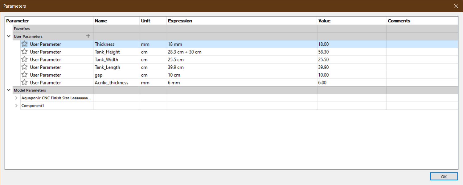 The solution is that when I want to cut the pieces on a CNC machine, I can set the thickness of the wood to 12mm.
The problem now is that the length of the joints will remain 18 mm, according to the old layout.
The solution is that when I want to cut the pieces on a CNC machine, I can set the thickness of the wood to 12mm.
The problem now is that the length of the joints will remain 18 mm, according to the old layout.
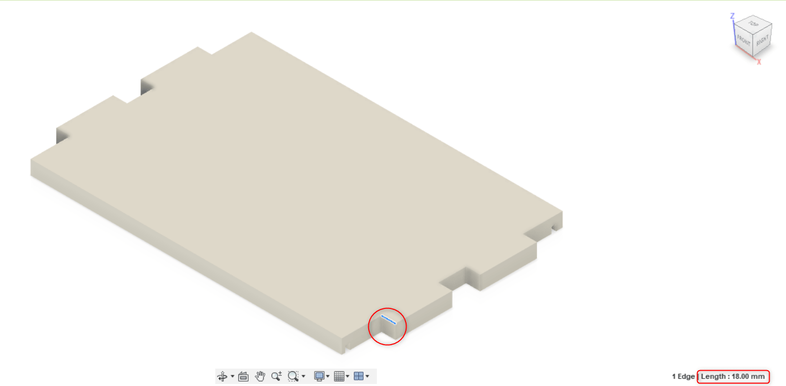 I used the “Offset Face” feature and set the distance as equal to the difference between 18mm and 12mm, which is 6mm, from each end I offset 3mm.
Milling
What is CNC?
A CNC (computer numeric control) tool is used for cutting, carving, machining and milling in a variety of materials including wood, mdf, plastics, foams and aluminum.
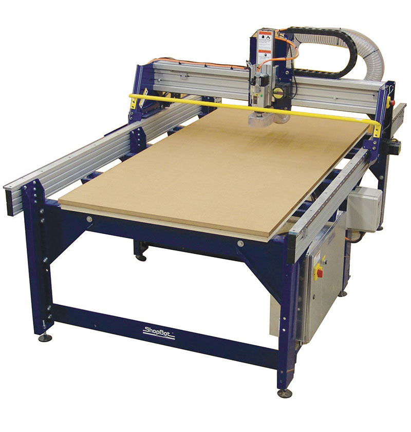
I will cut my design using ShopBot. ShopBot Tools, like all CNC tools, move a cutter around a big table “x,y,z-axis”. The cutter looks like a drill bit and is spun by a motor called a router or spindle. Unlike a drill bit, a router bit is designed to cut from the sides as well as the tip.
Steps
I followed the same steps listed in “CNC Shopbot” for Fablab Bahrain.
-
Export the design from fusion 360 as “dxf.” files.
-
Open “VCarve pro” program, “Create a new file”.
-
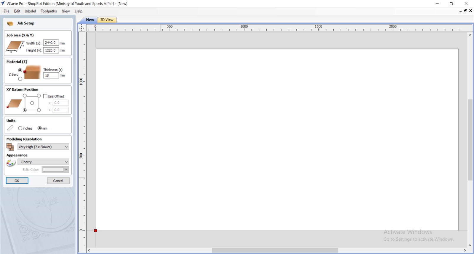
Enter the wood dimensions, the wood width and Height from “Jop Size” while the wood thickness from “Material (Z)”.
-
Choose the starting point “Datum Position”.
-
Import the file to the page, “File” > “Import” > “Import Vectors”. Set the design in the appropriate place for it to cut, place it 2 cm from the edges of the wood piece to avoid cutting it on the fixing screw, as well as to avoid cutting it out of bounds. To scale the design use the same tool.
 To move, scale and rotate the file:
-
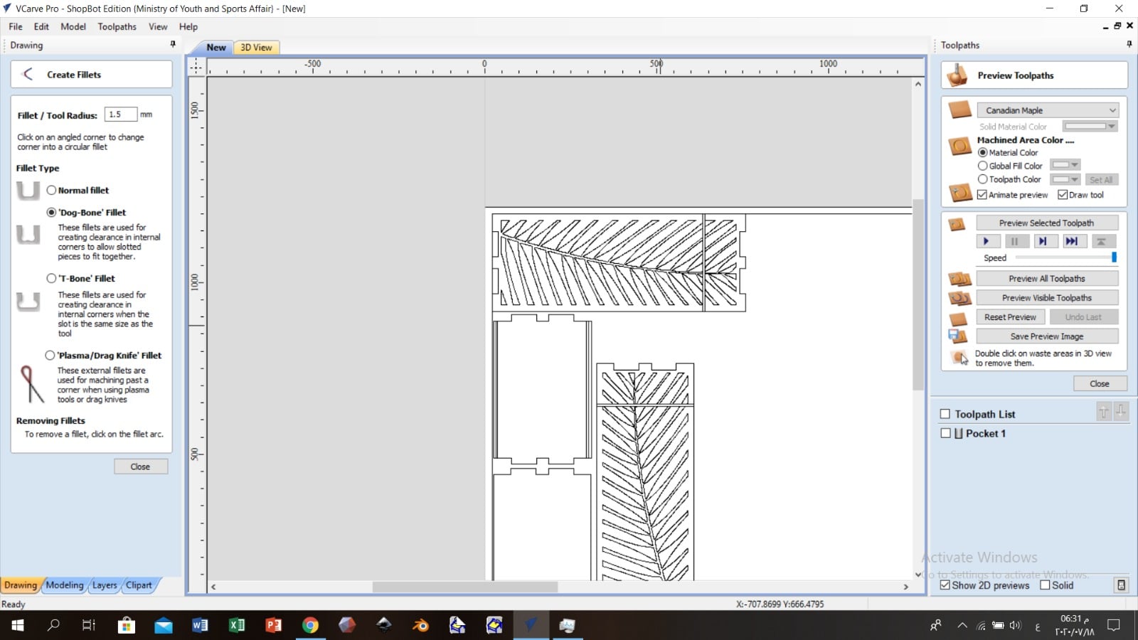
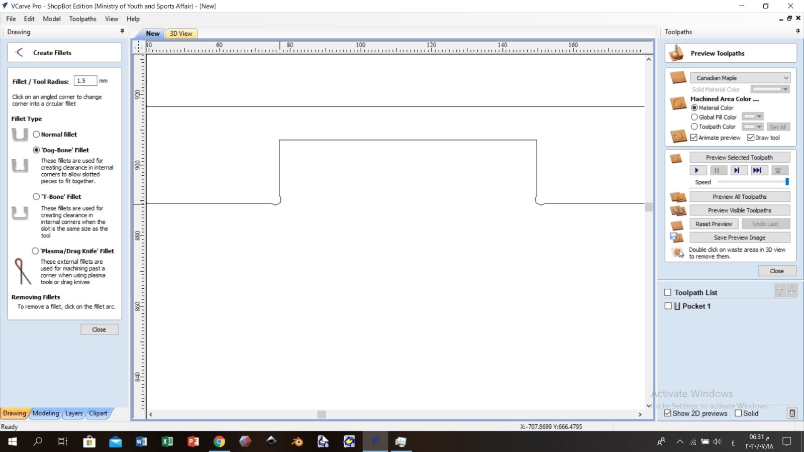
Choose the suitable “Fillet Type”, for me, I chose “Dog-Bone” so that the design does not move easily.
-
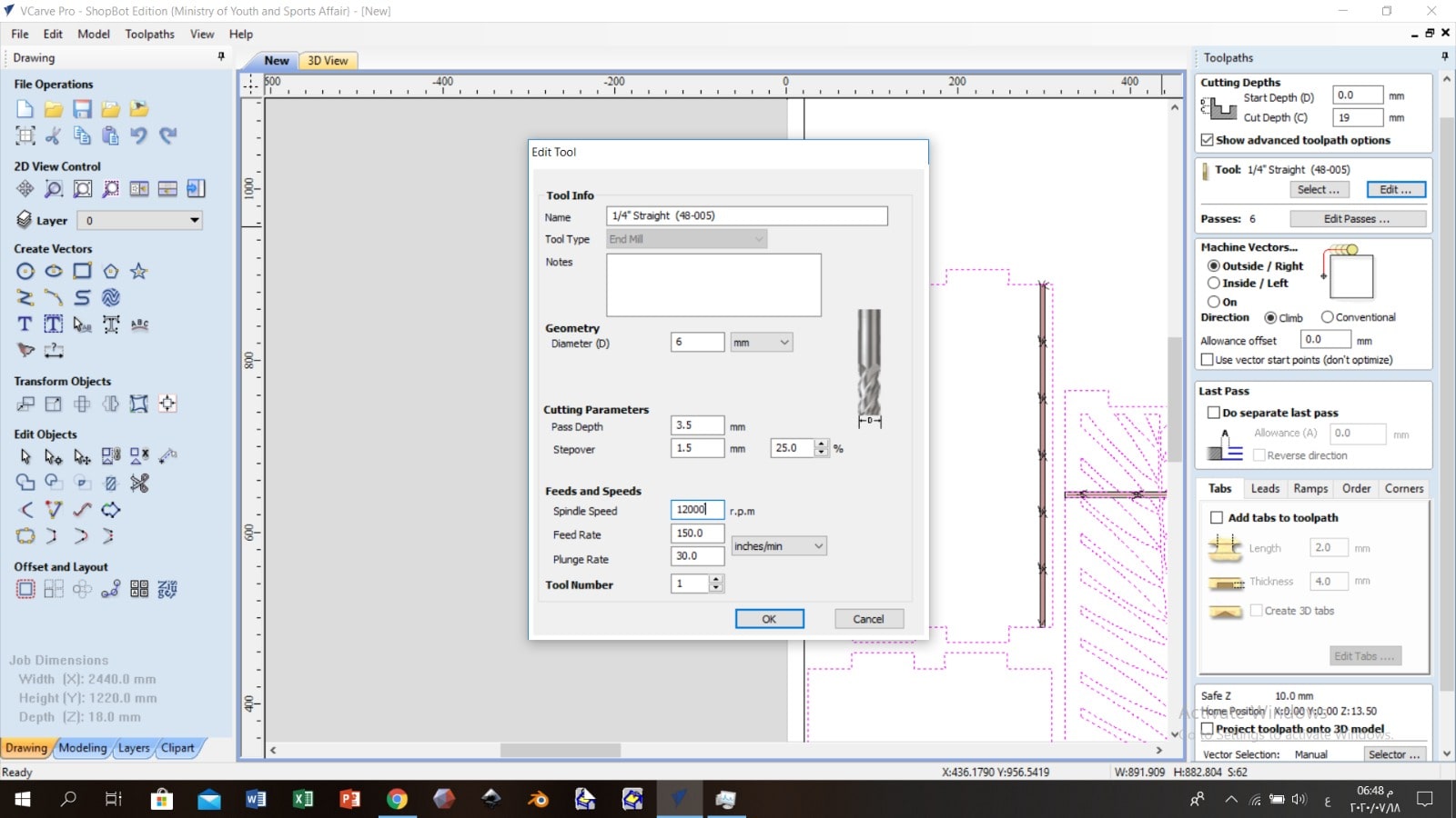
Each material will require different speeds and feeds settings. From “Toolpaths” tab; “Select” the drill bit which is “1/4 Straight” and click “Edit” to adjust the “Spindle Speed” ,”Feed Rate” and the “Plunge Rate”. I followed the numbers listed in the picture, because it based on Fablab Bahrain experiences.
Also from tool path set the cutting depth 1 mm more then the material sheet thickness to make sure that the parts have separated well.
 There are four main types of cutting tools:

-
Save the file and import it to “ShopBot” software and set the zero point “Datum Position”; Before that set the wood sheet and fix it with screws, set the drill bit.
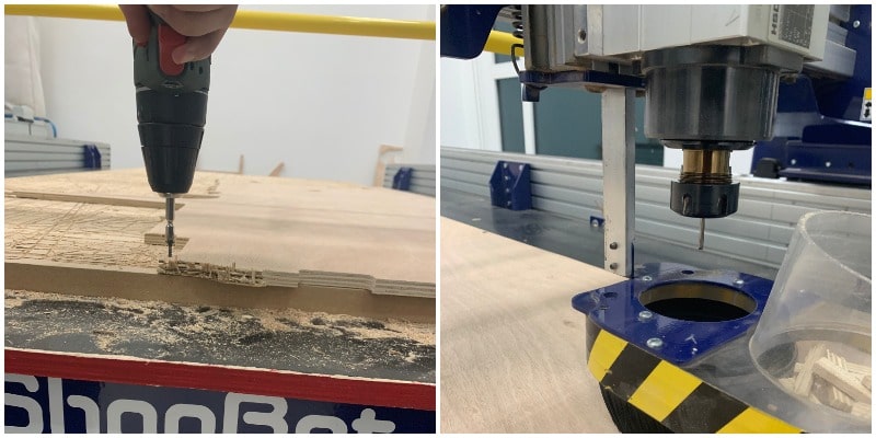
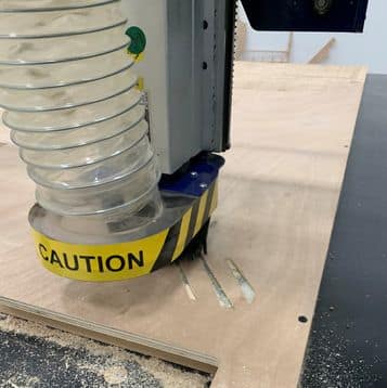
Start Cutting
Stick to wearing protective glasses from chipping off parts of wood, as well as wearing a headset when sitting for a long time in the room so that the ear is not affected by the strong, annoying sound that the machine makes.
Also, by repeating the same previous steps on the other side.
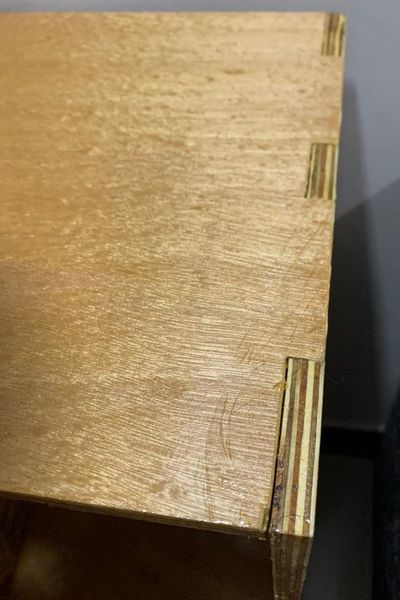
After the cutting was done, I rubbed the wood to remove the excess with “Shami paper”.
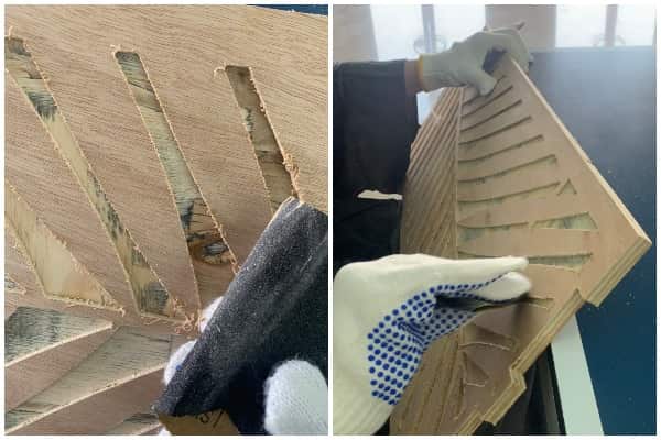
This is the difference between the piece before I rub it and after.
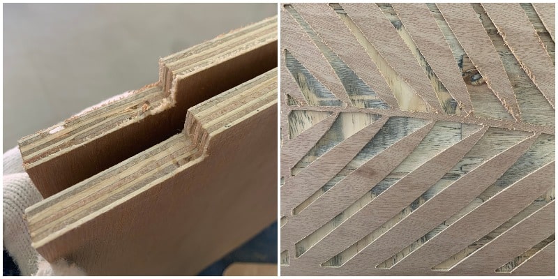
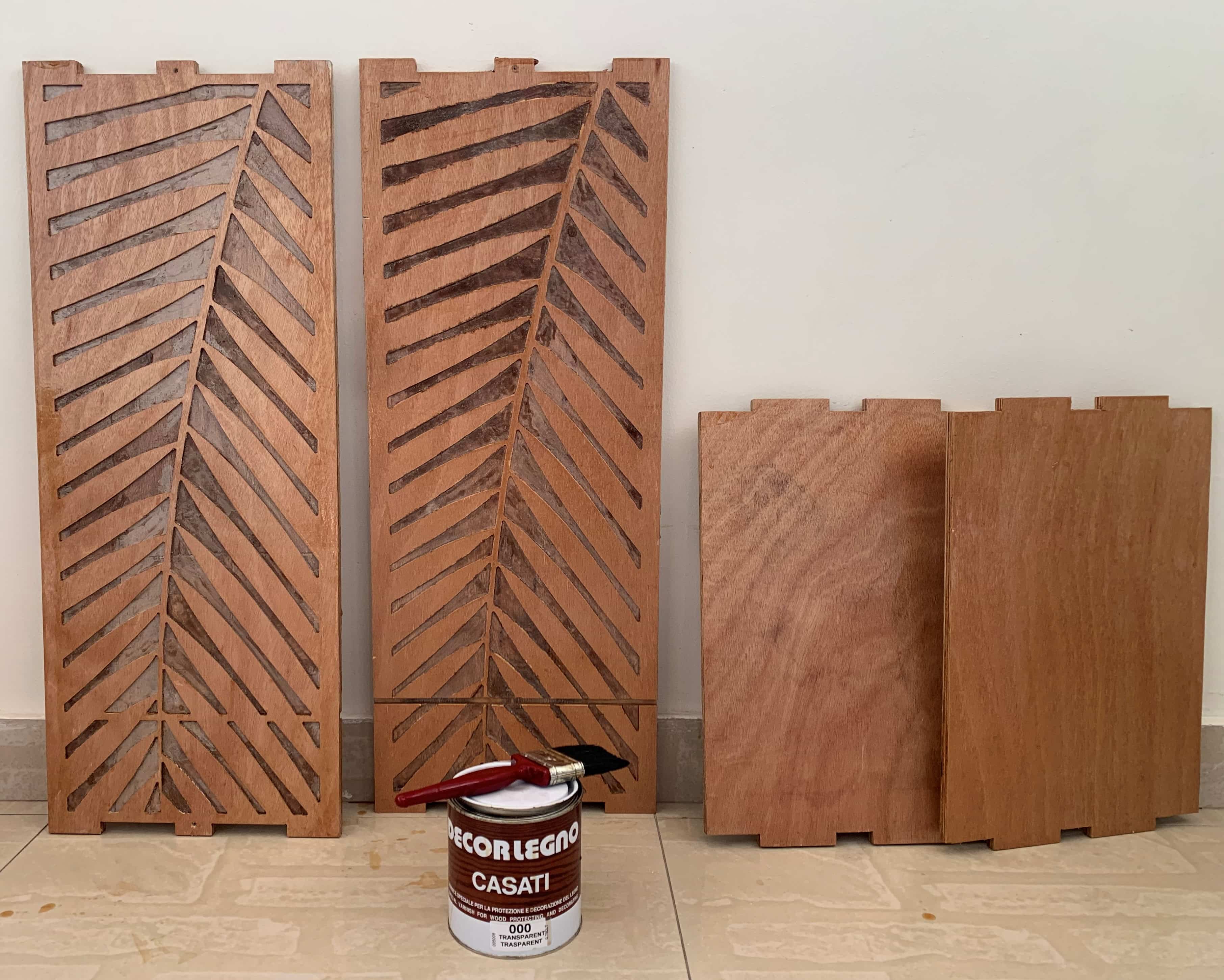
I dyed the blanks in the middle of the leaves a light brown color.
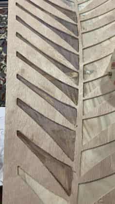
I also wiped the wood with varnish so that the wood does not absorb water and damage it, as the wood will be exposed to water due to the idea of the project.
Result
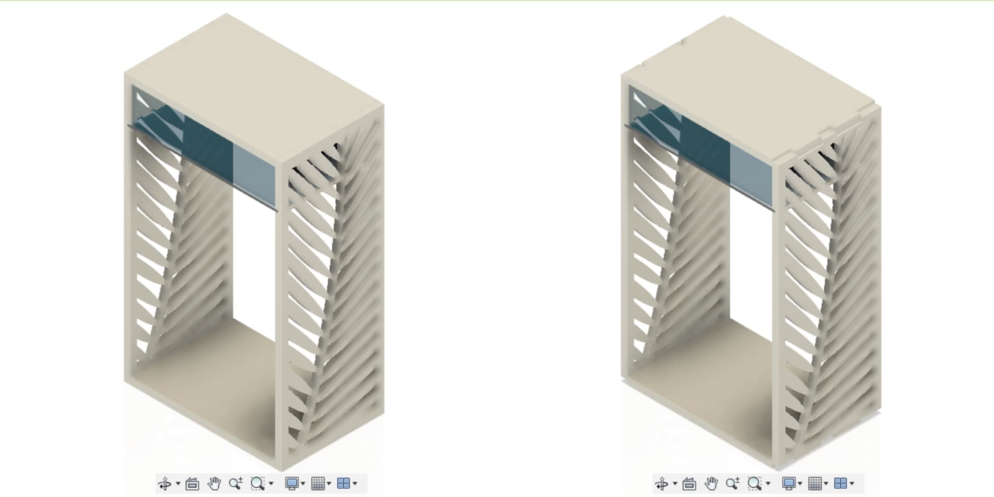
This is what wood looks like after it has been milled, dyed and togethered.
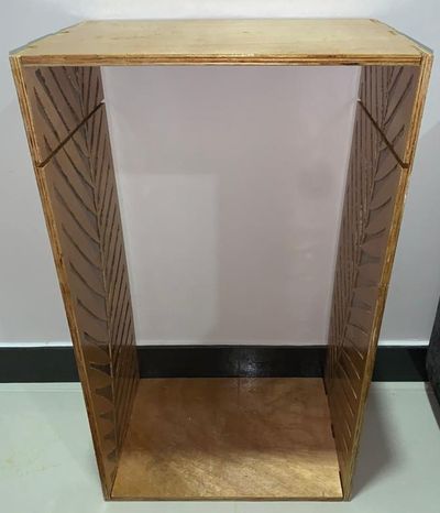
Here is an illustrative picture of the inside pockets I made, which is instead of the joints.
Dog Bones Joints, one of its advantages is that it needs hammering to put together, but dismantling it is difficult.
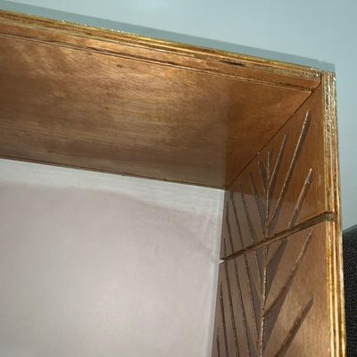
Acrylic with Lasercutter
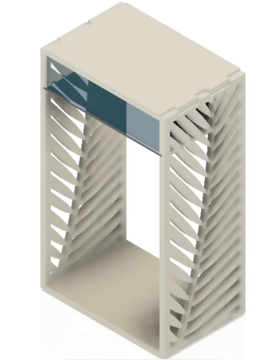
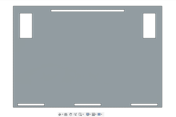
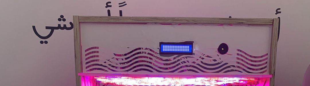
Top Acrylic Designs
This is the overall design, and on the right of the image is the default acrylic design. I will talk about the overall design later in the Computer Controlled Machining Week.
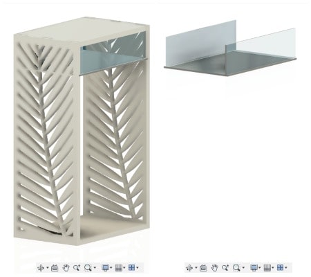
This is the acrylic design that I cut by laser.
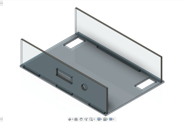
The front of the acrylic contains holes for putting the LCD screen that will display the sensor readings, with holes for fixing the LCD with screws. There is also a circular hole to insert the speaker alarm.
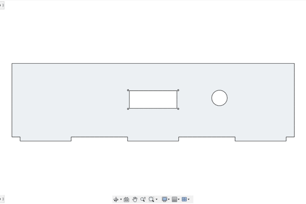
The top and bottom holes are for fixing the “previous” front piece and the back piece. The right and left holes are for getting wires, because this board is to hold the electronic parts and hang the grown lights.
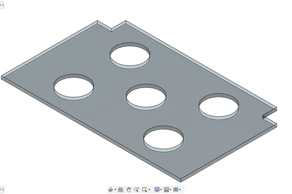
Bottom Acrylic Designs
This piece is designed to hold the five pots of plants, and the two squares in the corners are also used to extend the wires inside the fish tank.
ٌResult
Here are pictures I recently put up to show how I used laser cutting for acrylic. I chose acrylic because it adds beauty with its transparency, and also because it is waterproof.
This piece of pot holder was supposed to have curved corners rather than perpendicular angles, because I had to cut these corners in order to be able to fix them on the fish tank.

Files
Vinylcutter
I used vinylcutter to stick the sticker on the front acrylic board, to hide the set of wires inside.
Files
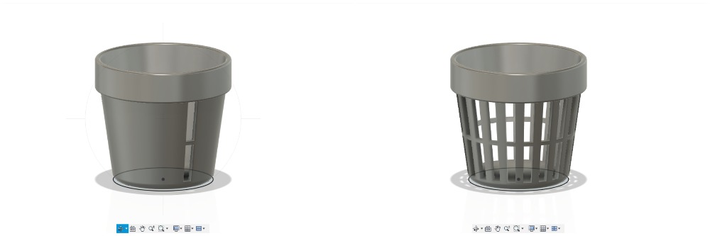
3D Printed Net Pots
I will design a net pot to hold the plants that will be sprayed with water. Four specific features were used in this design:
- “Offset Plane” which is to select a face or plane and specify offset distance to create a construction plane.
- “Loft” which is to select a series of faces to create a transitional shape between them.
- “Extrude”
- “Circular Pattern” by selecting faces, feature or body to arrange them in an circular pattern.
Also, I used the “Fillet” feature to round the net pot angles.
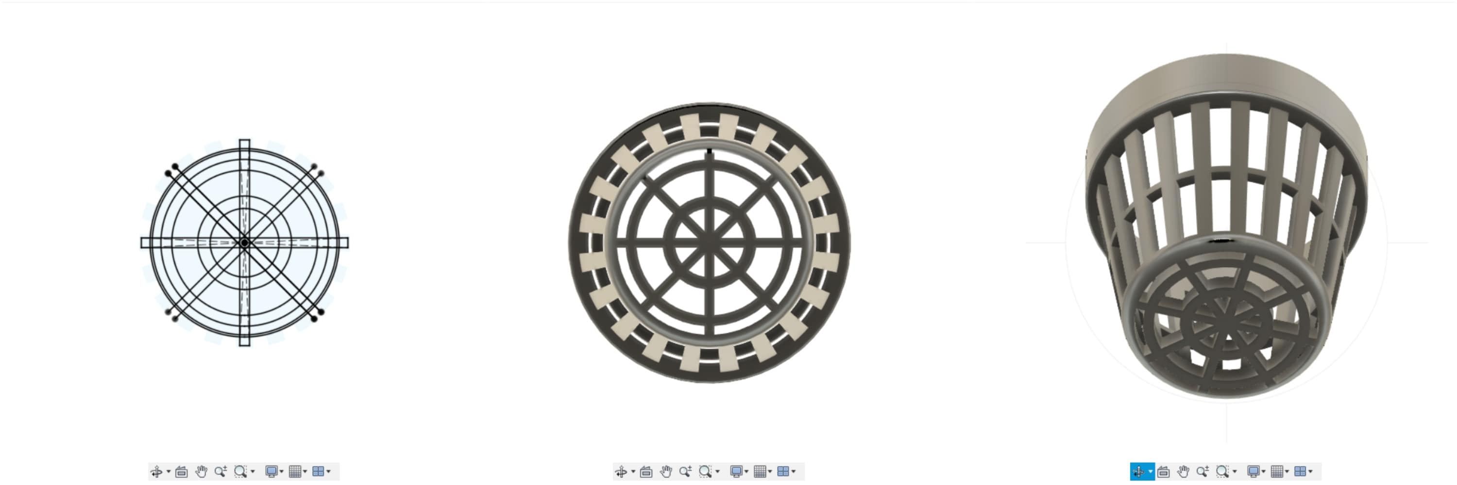
First I will draw the pot, using the “Offset” feature, I drew another circular base. To draw the upper part of it, I used the “Extrude” feature, while for the lower part, I used the “Loft” feature.
To empty the pot from inside, I also used the Loft feature.
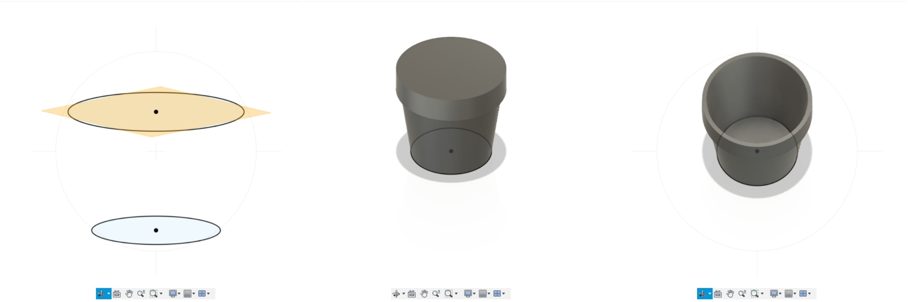
To cut the net from the pots, I drew one net on a plane, and then I cut it from the pot using “Extrude”. To repeat the net around the pot I used the “Circular Pattern”.
 I drew the holes for the bottom base and using an “Extrude” cut them.
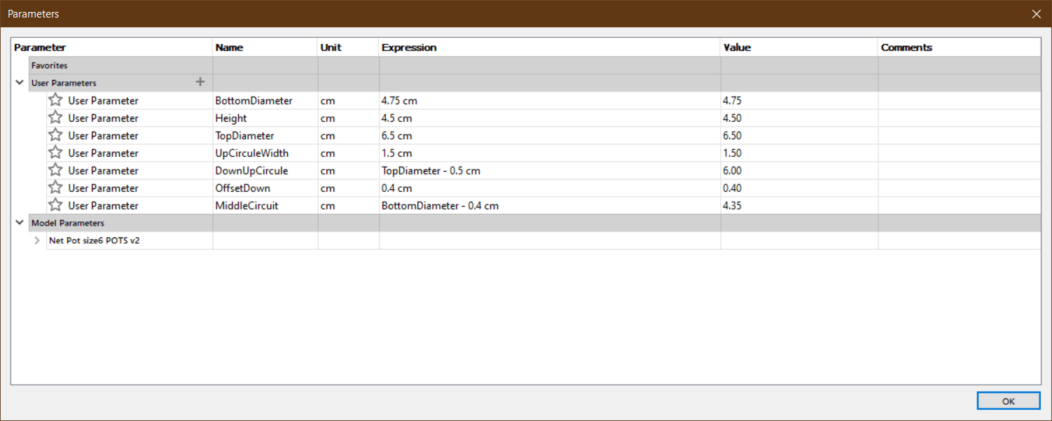
As for the size of the net pot, I designed 6cm in size based on these sizes.

I used a “parameter” to be able to change its size to the size I want whenever I want.
I used the net put I designed in Computer Aided Design week with the size 6.
Printing
I used the “Meshmixer” program and printed it in “Prusa”, but it did not work.
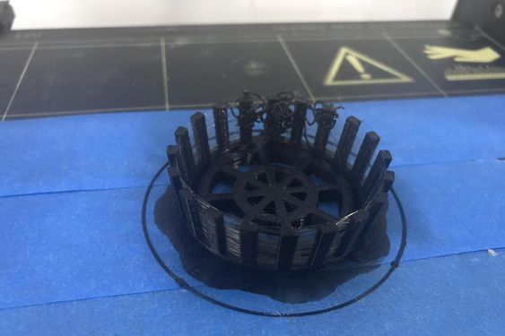
But here I make “Slicing” for it directly from “Prusa”, the settings are all normal, with the “Support”.
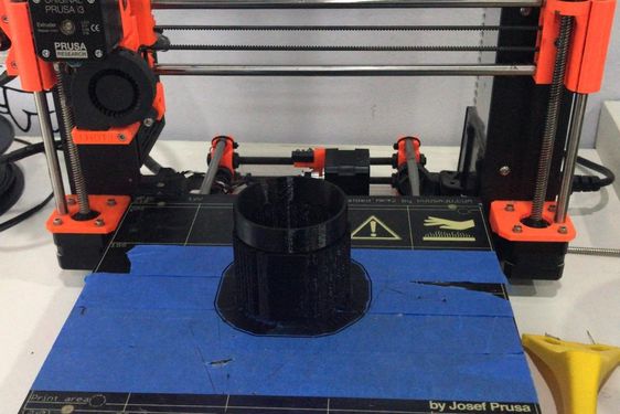
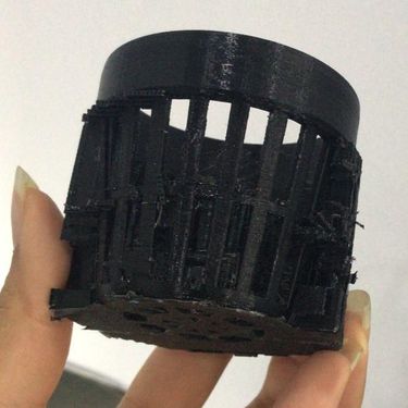
Here when removing part of the supporter. You can see its use in the Final Project.
Files
Useful Links
- Butterfly Valve Tutorial
- How To Make Threads In Fusion 360
Problems - When uploading pictures, they were shown to me on “Atom” program, but when pushing them to my FabAcademy site, they do not appear. It became clear to me after that, that the uppercase letter differs from the small letter of the site; When writing “flower” with the lowercase letter, the pictures do not appear on the site because the real filename is “Flower”, in the capital letter.
Files - Net Pot stl. - Net Pot f3d.
Mixoponics Gardening Summary Slide