12. Output Devices
Group Assignment
To view the group assignment click here.
Individual Assignments
Output devices are the opposite of input devices. They are devices that receive information from the computer and output it into a format that is usable by a person or another device. In this assignment, I will continue using the ATtiny44 PCB I produced with a Vibration Motor, also I will treat Arduino UNO with servo motor.
ATtiny44 PCB with Vibration Motor
The requirement in this assignment is to add an output device to a microcontroller board we have designed and program it to do something. I designed a board from the previous assignment to read the IR sensor and produce vibration with the output device “Vibration Motor”.
Vibrating Mini Motor Disc Overview
A vibration motor is a motor that vibrates when given sufficient power. It has very useful and practical applications. For example, the cell phones that vibrate when called when placed in vibration mode, also in rumble pack of a game controller that shakes.
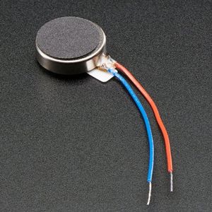
Pinout
A vibration motor has two terminals, usually a red wire and a blue wire but the polarity does not matter for motors. These two wires are used to control the vibe, and simply vibration motor can be powered from a battery or microcontroller pin with a tension between 2 to 5 Volts. The greater the tension, the greater the vibrations produced and the current consumed.
To see the datasheet for this vibration motor click here.
Sources
- How to Build a Vibration Motor Circuit
- Vibration Motor test
PCB Production
I am going to use for this assignment my previously made board which contain button and LED and headers dedicated to input and output devices.
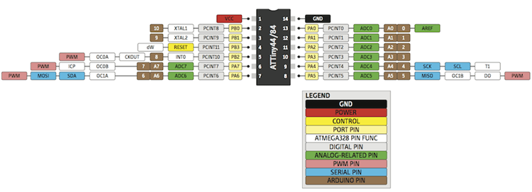
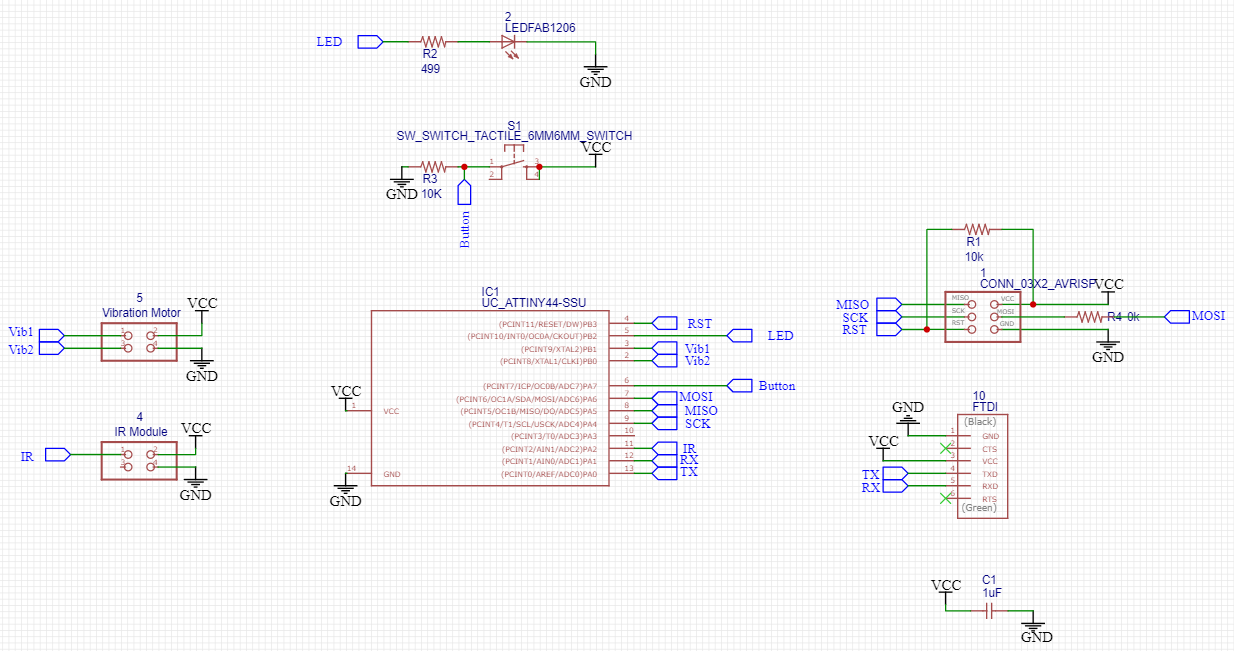
I designed ATtiny44 PCB with EasyEDA software, I added the components to a new schematic, a headers to facilitate connecting the IR sensor and the mini motor that I will use for this assignment. I need a digital pin to connect the vibration motor, I chose pin2 from the ATtiny44, pin10 in Arduino. Also, I connect an extra header to pin3 may I need it in any other projects.
This is the final schematic circuit shown below.
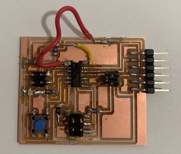
This is my PCB, and because I missed connecting the ATtiny44 VCC and GND, I connected them manually with soldering jumper wires.
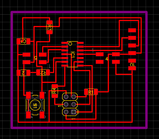
This is my final PCB after I soldered all components and the jumper wires.
To see more steps on producing this circuit take a look at the Input Devices Assignment.
Programming
To program the board, I think about using both the IR sensor and the vibration motor together, so the way the code works is that when an object approaches the sensor, the motor vibrates, and on the contrary, when there is no object, it does not emit any vibrations. I will use my FabISP and the Arduino IDE for programming.
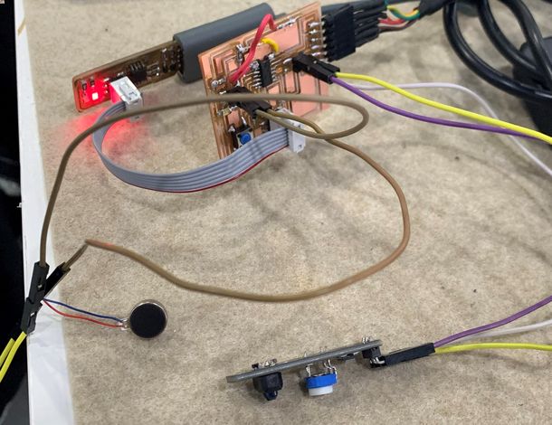
I connected the ATtiny44 PCB to the FabISP headers and to the FTDI cable to get power. I connected both. the IR sensor “Vcc, GND, pin11” and the mini motor “GND, pin2”.
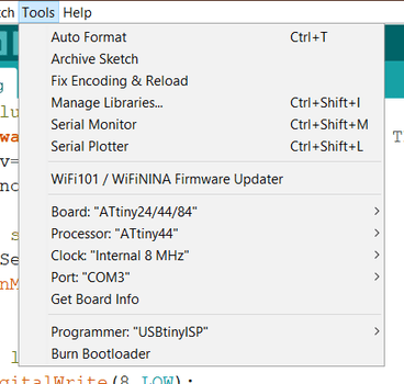
Prepare to program the board from tools, and upload the code after that.
This video shows the successful attempt in programing both the IR sensor and the mini motor using my ATtiny44 PCB.
Source Code
int IRSensor = 2; // connect ir sensor to arduino pin 2
int LED = 8; // conect Led to arduino pin 8
int Vibration_motor = 10; // conect Vibration motor to arduino pin 10

#include <SoftwareSerial.h>

SoftwareSerial mySerial(1, 0); // RX, TX


void setup()
{
  mySerial.begin(9600);

  pinMode (IRSensor, INPUT); // sensor pin INPUT
  pinMode (LED, OUTPUT); // Led pin OUTPUT
  pinMode (Vibration_motor, OUTPUT); // Led pin OUTPUT
}

void loop()
{
  int statusSensor = digitalRead (IRSensor);

  if (statusSensor == 1){
    digitalWrite(LED, LOW); // LED LOW
    digitalWrite(Vibration_motor, LOW); // LED LOW
      mySerial.println("nothing detected");
  }
  else
  {
    digitalWrite(LED, HIGH); // LED High
    digitalWrite(Vibration_motor, HIGH); // LED High
    mySerial.println("detected!!!!!");

  }

}
Files
- I/O ATtiny44 PCB Schematic sch.
- I/O ATtiny44 PCB brd.
- Toplayer for Milling - I/O ATtiny44 svg.
- Hole for Milling - I/O ATtiny44 svg.
- Outline for Milling - I/O ATtiny44 svg.
- Vibration Motor Source Code ino.
SM-S2309S Servo Motor
In this part I will add “SM-S2309S Servo Motor” output device to my Attiny44 board I have designed in Electronics Design week.
SM-S2309S Overview
Servo motors are a device that can turn to a specified position, usually it have a servo arm that can turn 180 degrees.

Pinout
On the servo we will have 3 wires, one power line, one ground, and one control pin.
Schematics
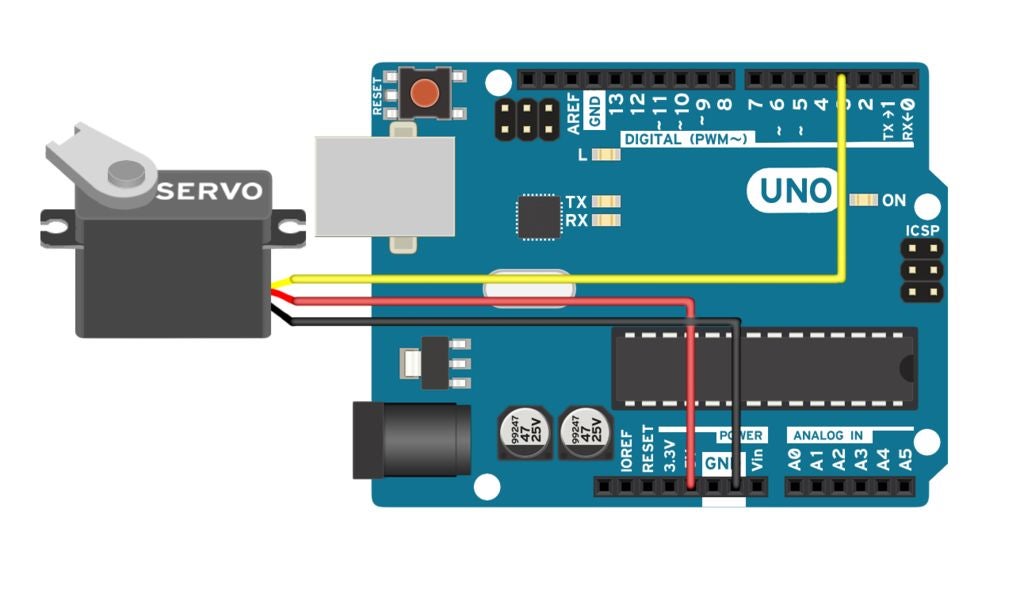
Below is the connection between the servo motor and Arduino. I connected the ATtiny44 board ISP to Arduino, the way I connected it to the Embedded Programming week.
- The servo motor has a female connector with three pins. The darkest or even black one is usually the ground. Connect this to the Arduino GND.
- Connect the power cable that in all standards should be red to 5V on the Arduino.
- Connect the remaining line on the servo connector to a digital pin on the Arduino.
Code
The following code will turn a servo motor to 0 degrees, wait 1 second, then turn it to 90, wait one more second, turn it to 180, and then go back.
// Include the Servo library
#include <Servo.h>
// Declare the Servo pin
int servoPin = 3;
// Create a servo object
Servo Servo1;
void setup() {
   // We need to attach the servo to the used pin number
   Servo1.attach(servoPin);
}
void loop(){
   // Make servo go to 0 degrees
   Servo1.write(0);
   delay(1000);
   // Make servo go to 90 degrees
   Servo1.write(90);
   delay(1000);
   // Make servo go to 180 degrees
   Servo1.write(180);
   delay(1000);
}
Result
Useful links
- Arduino Servo Motors
- Servo motor controlado mediante sensor ultrasonico(HC-SR04) 2.0
- Youtube video ID & thumbnails finder
My Final Project Output Devices
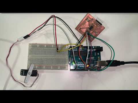
In this part of assignment, I will show the ATmega328 PCB that I made for the final project, and review the part dedicated to the output devices. For details, see the final project page.
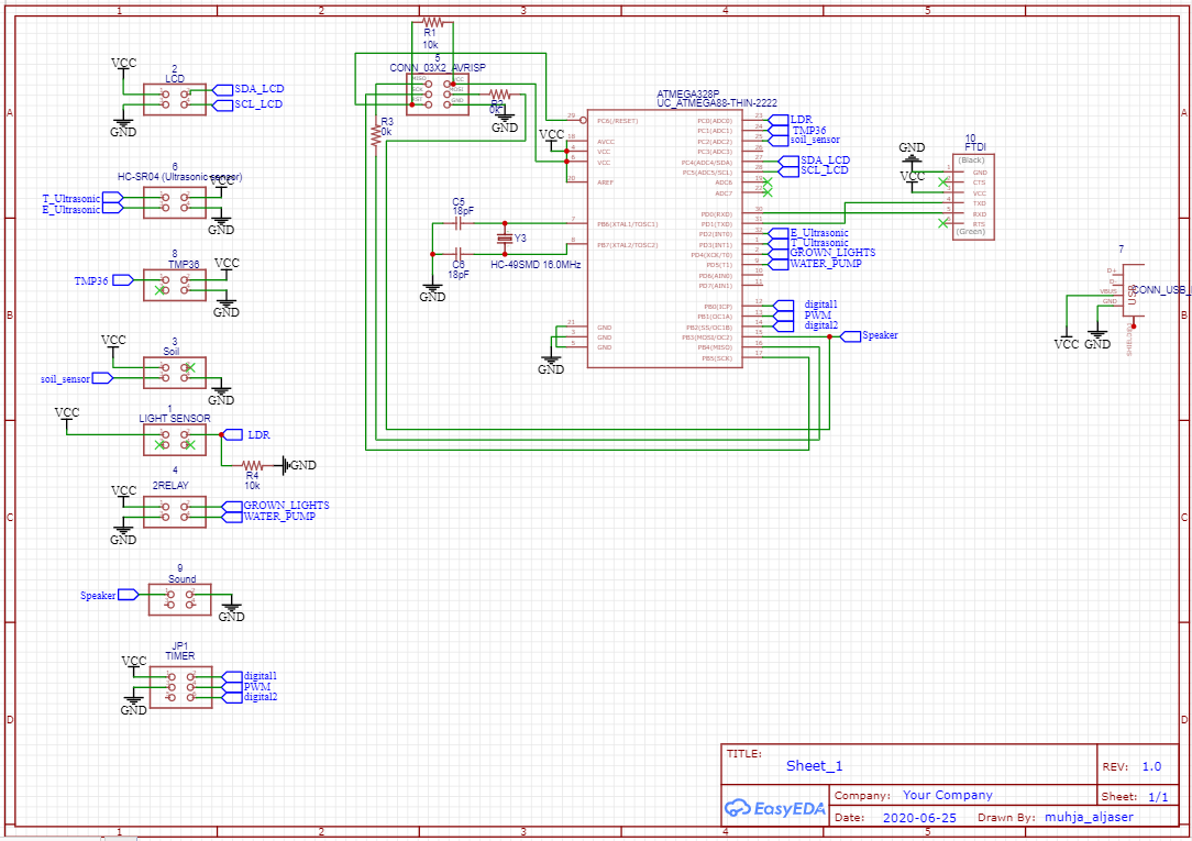
This is schematic for my ATmega328 PCB. On the lower left side of it, there are two of the four headers, one for two relays and the other for a speaker.
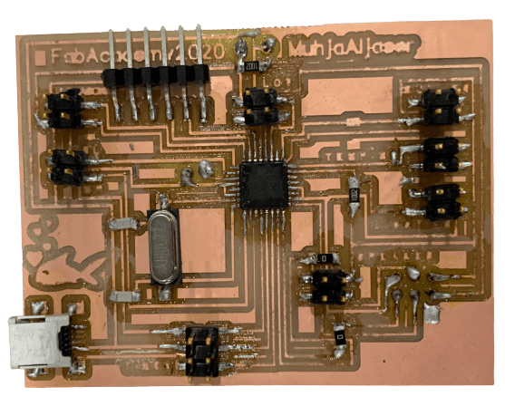
This is how the PCB looks after soldering, which I will use to program the output devices.
The Output Devices
In my project, I used three output devices that will receive information from the input sensors and output it into its function to operate the system.
Passive Piezoelectric Buzzer “PKM22EP-20”
A buzzer is a small component and compact two pins structure to produce sound.
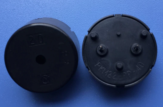
There are two types are buzzers, a simple buzzer that makes a continuous sound, the other type is called a readymade buzzer and will produce intermittent sound due to the internal oscillating circuit present inside it. I used the second type in my project.
I connected the speaker PCB headers to pin11 from the ATmega328, a digital pin, and the other pin of the speaker I connected it to the GND.
Sources
Two Channel Relays
A relay is an electrically operated switch. Both of the Submersible pump and the Grown Lights are controlled from two relays.
When the intensity of the light falling on the LDR increases, the relay will be deactivated and appliance will be turned OFF
-
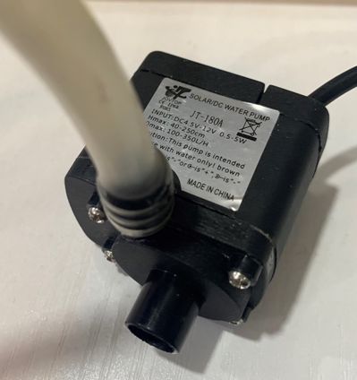
Submersible pump: This is the pump I used, where there is one hole in which the water comes in from the aquarium, and the other to water the plants.
-
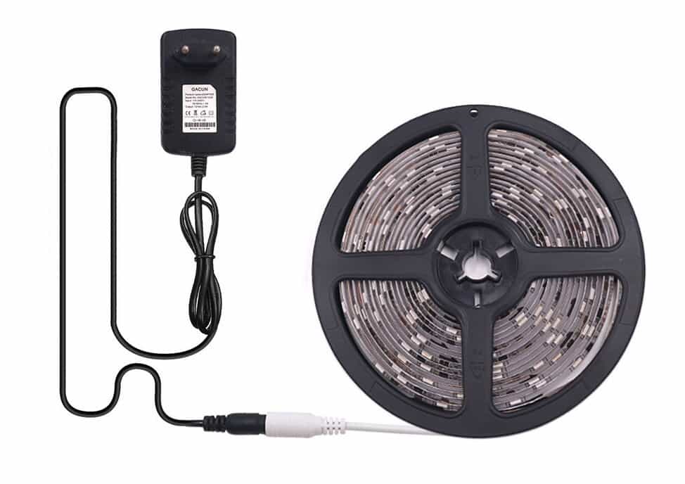
Grown Lights: The one I used is as a long strip, as shown in the image.
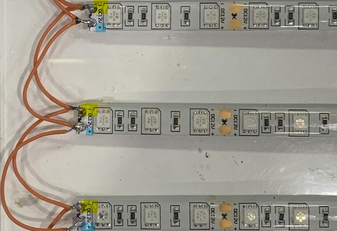
I cut the long strips into small strips, soldered them and stuck on the acrylic board that I cut with a laser cutter.
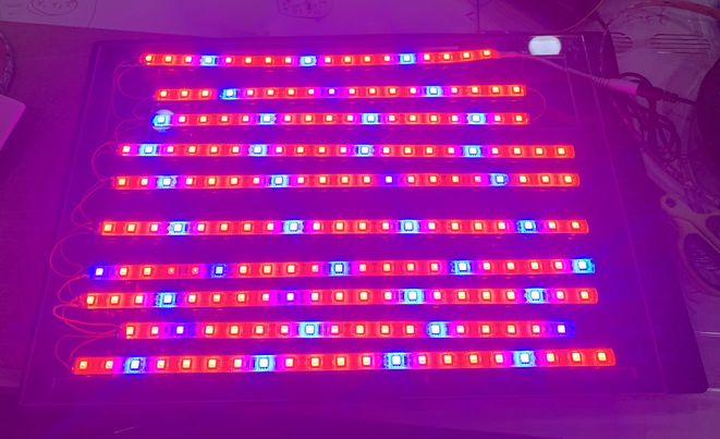
This is the final form of welding. I connected the electricity to the tape, and now it is fully lit.
Pinout
The two channel relay module could be considered like a series switches; Two normally Open (NO), two normally closed (NC) and two common Pins (COM).
It has four pin header for connecting power, ground, and for controlling the two relays. There are two LEDs to indicate when relays are on.
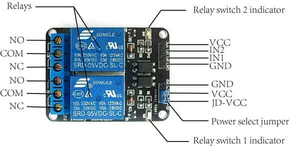
The VCC and GND pins for the relay module are given from the PCB, IN1, and IN2 connected to the PCB headers also, which will be triggered by the PCB with the help of the sensors.
Connection
I used two “Power Outlet box”, each with one plug and a switch. The switch provided on the power outlet box can be manually used to turn ON or OFF the appliance plugged into the socket.
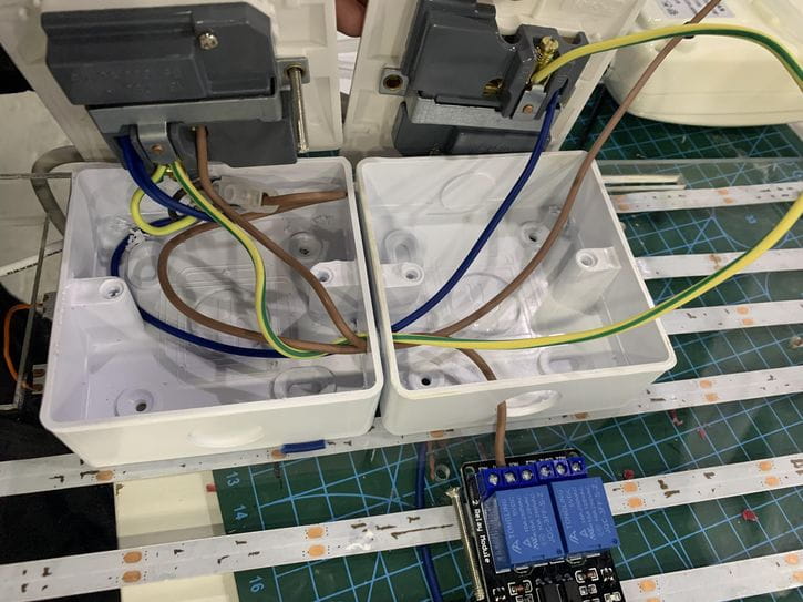
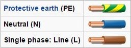
Both the boxes and relays will be connected by three colors of wire. This is the wire color code:
First, connect the “neutral wire” from the supply to the neutral connector on the socket.
The second terminal of the switch (top terminal) is connected to the Line (Hot) wire from the supply and also to the COMM (Common) terminal of the Relay.
Connect the other connector on the socket to one end of the switch (bottom terminal) and also to the NO (Normally Open) contact of the Relay.
Connect the “Protective Earth” and “Natural” wires from the first socket to the other socket. Do that for the “Line” wire.
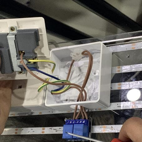
CAUTION: BE VERY CAREFUL WHEN CONNECTING WIRES, AND PAY ATTENTION TO THE COLOR CODE OF THE MANUFACTURER..
Output Work
The process is the following. The ultrasound will read the height of the water in the aquarium, if the height of the water is less than the required rate, we will hear a sound from the speaker to alert, and “NO WATER :(” phrase will also appear on an LCD screen, which requires adding more water to the aquarium.
After adding the water, or when the height of the water is appropriate, it will move to the next step, which is spraying the plants from the aquarium water, or in other words, the relay will be activated and the submersible pump will be turned ON to spray the plants. The pump will turn on only when the humidity is less than 45% in the plant’s environment.
The third step is to read the light sensor. If the lighting that the plant is exposed to is insufficient, the relay will be activated and the light will be turned ON, and if it is sufficient, it will be deactivated and the light will be turned OFF.
Also no matter how low the humidity of the plant’s surroundings is if the water level below normal.
The code for taking sensor readings and output it into turning ON and OFF the speaker, pump, and lights, can be download from the below files.