4. Computer Controlled Cutting
Group Assignment
To view the group assignment click here.
Individual assignments
This week I will be doing several tasks. I will test laser cutting on “sturdy paper”, as most of the work we do in the Fablab are all based on previous tests in using materials, like the parametric press-fit kit I will cut it next on a “mat board”. Also I will cut my logo design from the previous week on the vinylcutter. Finally, I’ll show my use of laser cutting and vinylcutter for my final project.
Lasercut on Sturdy Paper
HT-9060 CO2 laser machine Overview
There are different types of laser cutters, hobbyists and small businesses most commonly use gas lasers and CO2 laser, while industrial applications mostly use other types like fiber or crystal lasers. The laser cutter that I will be using is “RDWorks”, it is kind of laser engraving cutting machine system equipped with CO2 laser tube.

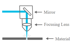
In a CO2 laser cutter machine, the laser beam is created in a tube filled with CO2 gas, and with the help of mirrors and lenses, the laser beam is directed to the laser head and focused on the material surface. Electronically controlled motors move the laser head.
Power and speed are among the most important settings for the laser cutter. This machine power is 100 watt, the output power of the laser set from 0 to 100%, high power is used for cutting thick materials and lower power is used for engraving and cutting of thin materials. For engraving and cutting of thin material, the movement speed is usually set close to the maximum.
Source
Steps of Process
The laser cutter is a practical invention that often keeps from using scissors in arrangement and speed, it cuts neatly and clean if the appropriate power and speed of the material is suited. Through my presence in the Fablab, it is necessary to monitor the laser cutter when it is cutting, because burning may occur at any unexpected second, and also safety and security precautions must be taken. I will use the “RDWorks” software for these next steps:
-
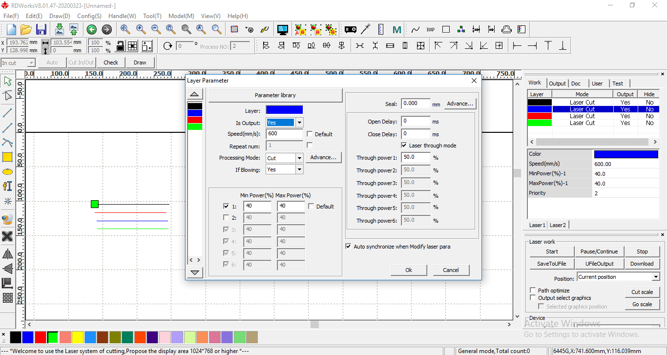
Here I will laser cut the strong paper into four lines that I drew. I select different “Power” and “Speed” for each of them for testing. Choose “Cut” for the “Processing Mode”.
-
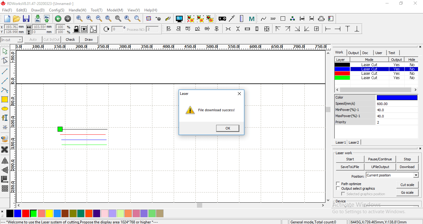
After selecting the settings, click on “Download” to send the file to the laser cutter.
-
Fix the paper inside the machine.
-
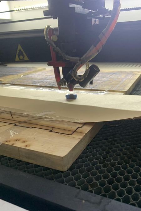
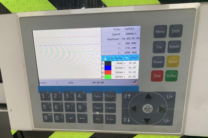
Now going to the screen of the laser cutter. The height of the laser should be at a distance of “8 mm” from the surface, this small cube is in “8 mm” height. The height is adjusted from the “z-axis”.
When pressing the “Frame” button, the machine shows us the space that will be consumed for laser cutting. This step is important to ensure that no cutting outside the boundaries of the material or cutting on the plastic tape attached to the paper.
The specific speed and power of each line can be seen also in the screen.
-
Click the green button to start cutting.
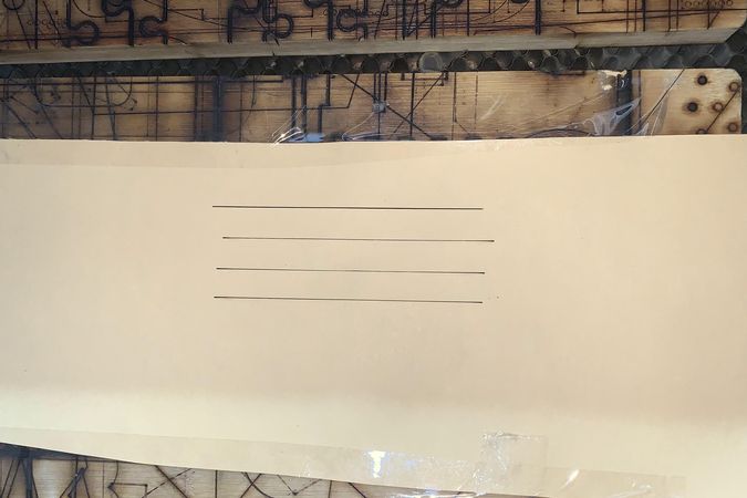
This is the result, and it seems that all the lines have been cut.
-
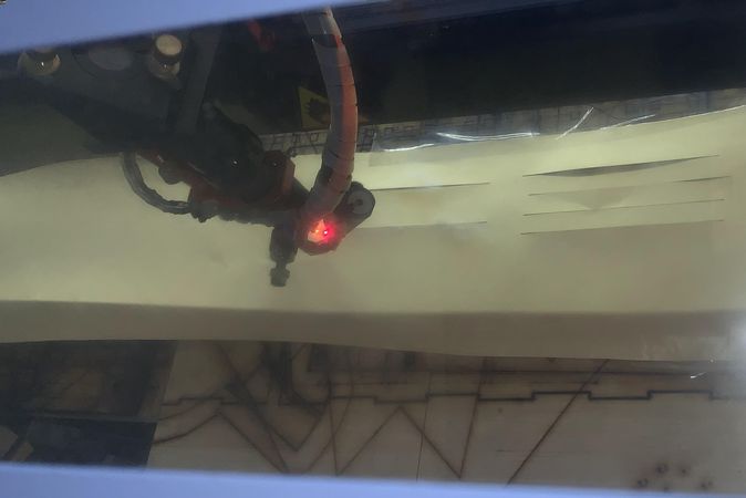
To choose the best settings, I re-cut and note the laser tool when cutting, the line that requires the least spark from the laser is the most appropriate. The cutting was very fast, I suspect the third blue streak is the least sparkling.
Lasercut on Acrylic
Among the previous uses of the laser, these are suitable settings for laser cutting on “acrylic”. The speed is “25 mm/s” and the energy is “65%”.

Lasercut on Mat Board
From my colleague “Mariam” in Fablab, the proper settings for laser cutting on the “mat board” is “71 mm/s” for the speed and “50%” for the power.
Press-Fit Kit Laser Cutting
These are the type of joints, and as required I am going to design Press-Fit Kit.

Here I will design a set of 2D parametric objects using “Fusion 360” that can be assembled and put together in multiple shapes and ways. Then I will transfer the design to reality through the laser cutter. This design can be given to the children to play, as a table or organizer of things when printed at the appropriate size.
Design Press-Fit Kit
-
First you have to set a Parameters.

-
Sketch a large rectangular, with a small ones in the edges of the large rectangular using the Parameter.
Use the “Trim” to erase the undesirable edges and “Fillet” to circulate the corners.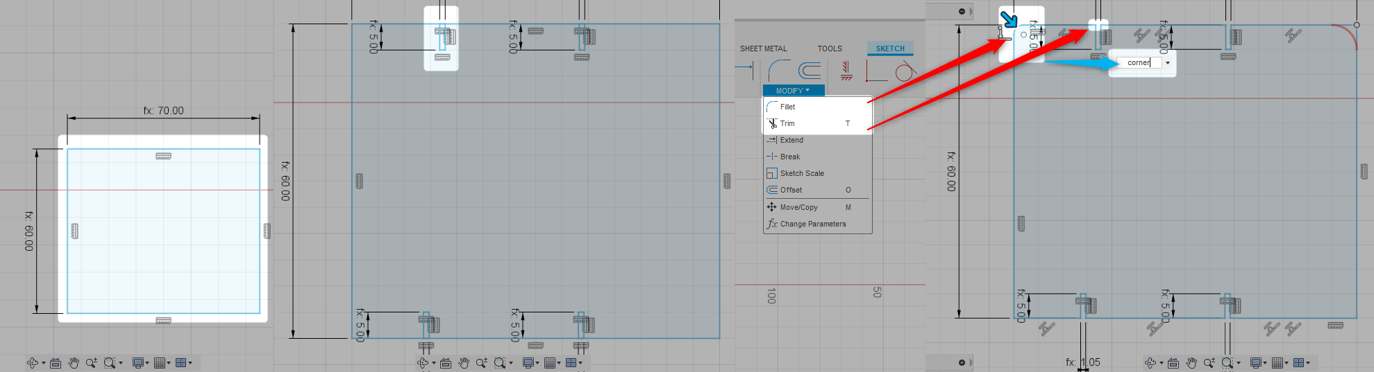
-
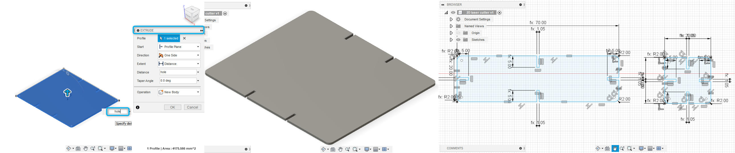
“Extrude” the rectangular and apply the previous steps to create two more joints.
-
Export the file as “dxf.” to import it in “RDWorks” software.
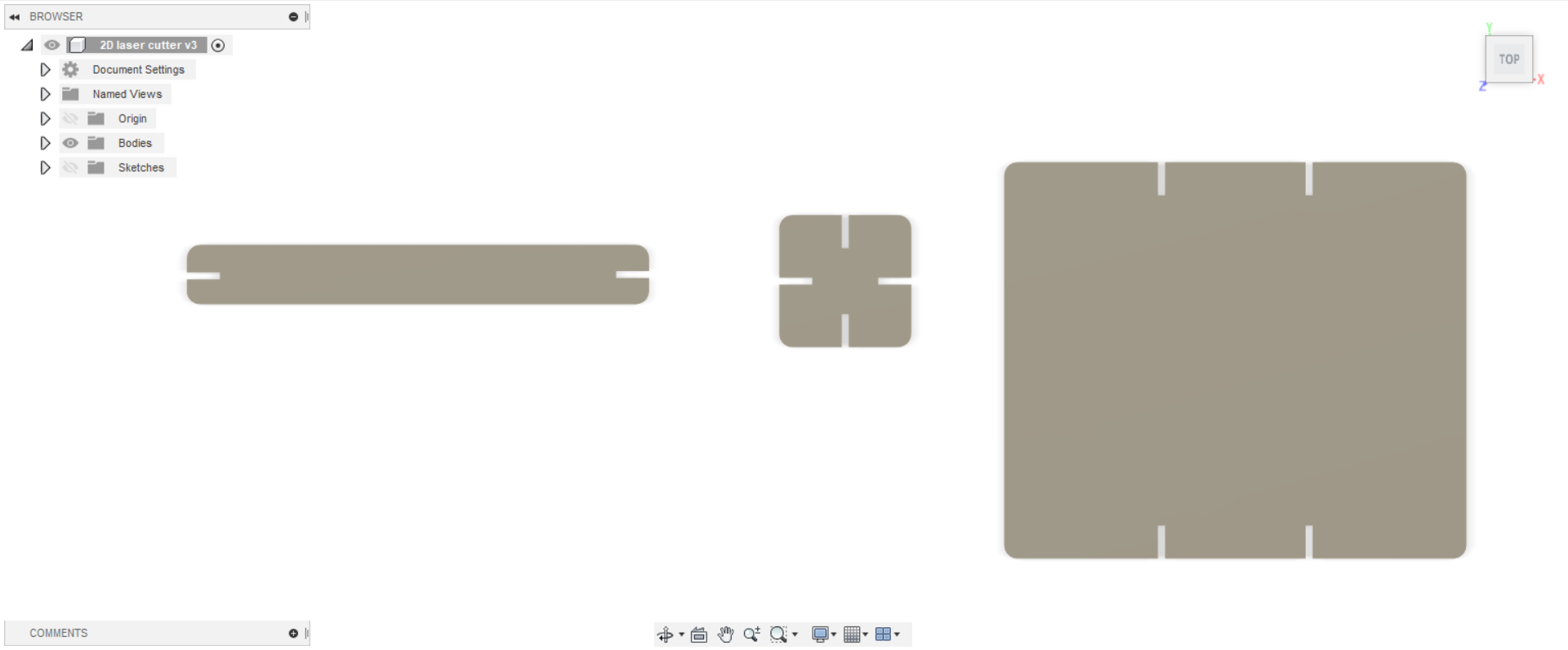
The Final Design
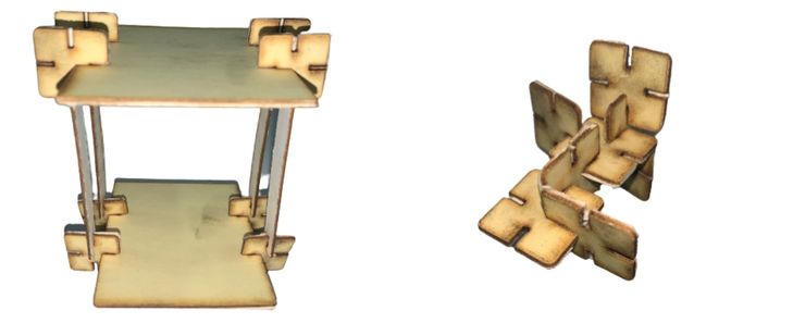
Laser Cutting
I cut the design at “71mm/s” and “50%” power on a “mat board”.
Files
Vinyl Cutting
I used the 2D design from the previous week, and by changing “FabAcademy” to my name “Muhja Aljaser”; That’s to cut it with “”Silhouette Cameo 2” vinyl cutter.
This small device lends a lot of beauty to things when using it, the downside I found is that it takes a lot of time in details.
Cut the Sticker
-
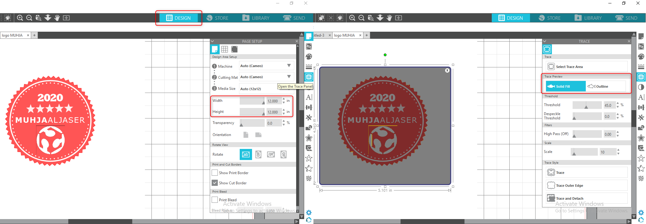
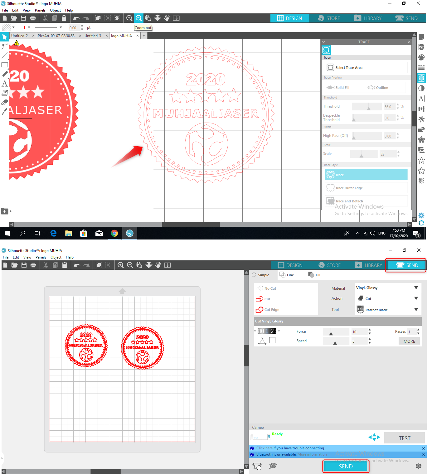
To start with, install silhouette studio software and import your design image to the software. Click on “Trace” and move the original image away and delete it, you will see the trace that the vinylcutter will draw. Choose the “Trace Preview”.
-
Specify the “Force” and “Speed” to engrave and then “Send” the file to the vinylcutter.
-
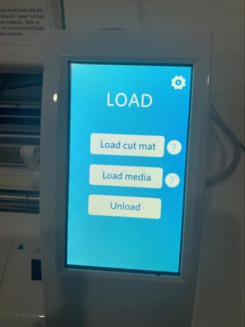
Click “Load cut mat” on the touch screen to take the adhesive paper and start engraving on it. After the engraving click on “Unload”.
After Cutting
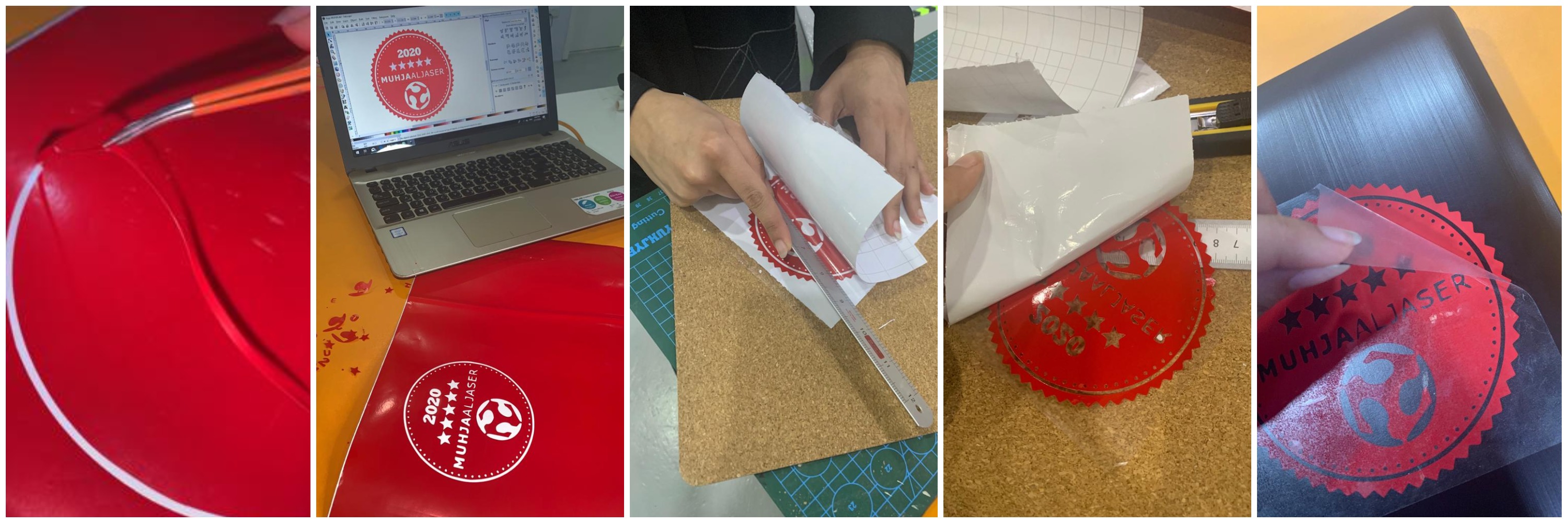
- Remove the unwanted sticky paper, I used tweezer for that.
- Put a transparent sticker on it, and put it on the surface you want to add it to. For me, I put the sticker on my laptop.
- Remove the transparencies again.
The Final Result

Problem
I didn’t put the fixer on the edges of the paper and the presence of a small material in the device prevents the paper from going in the right direction.

Useful Links
To my Final Project
Lasercut
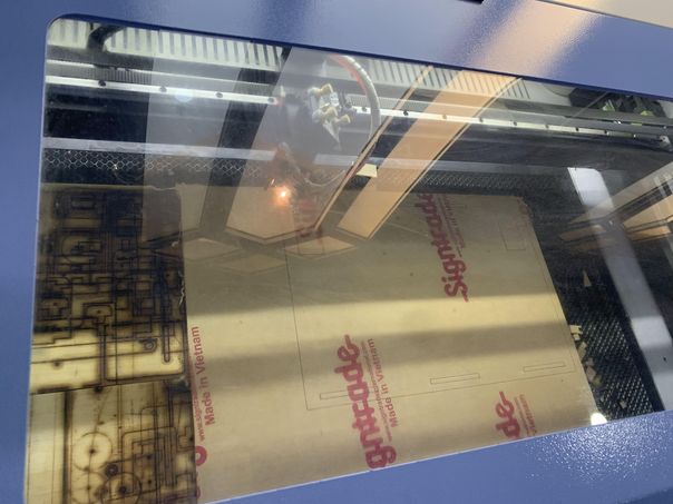
Top Acrylic Designs
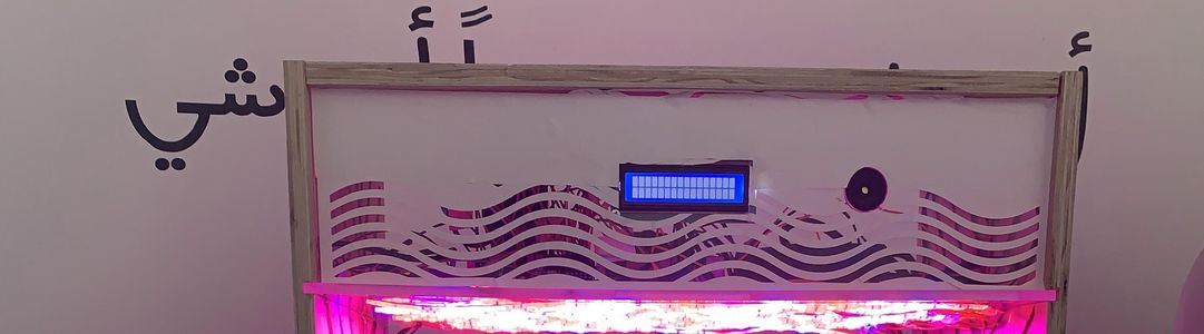
This is the overall design, and on the right of the image is the default acrylic design. I will talk about the overall design later in the Computer Controlled Machining Week.
This is the acrylic design that I cut by laser.
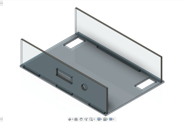
The front of the acrylic contains holes for putting the LCD screen that will display the sensor readings, with holes for fixing the LCD with screws. There is also a circular hole to insert the speaker alarm.
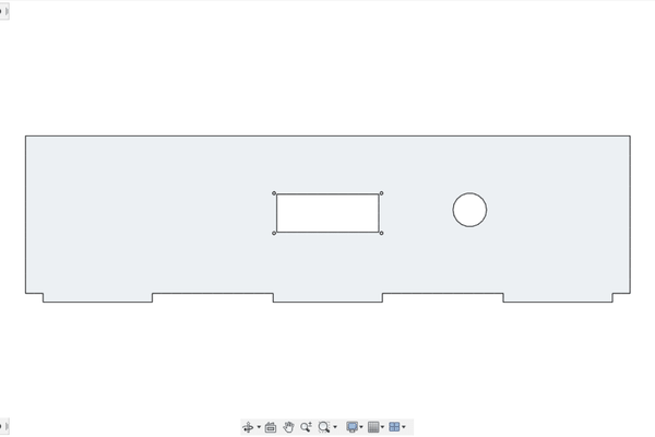
The top and bottom holes are for fixing the “previous” front piece and the back piece. The right and left holes are for getting wires, because this board is to hold the electronic parts and hang the grown lights.
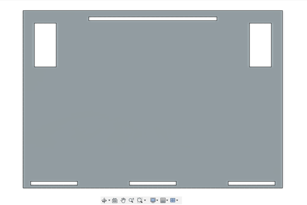
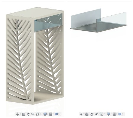
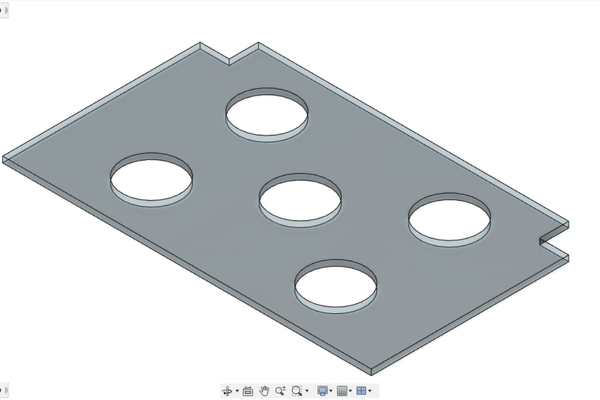
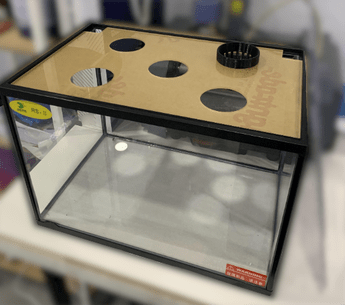
Bottom Acrylic Designs
This piece is designed to hold the five pots of plants, and the two squares in the corners are also used to extend the wires inside the fish tank.
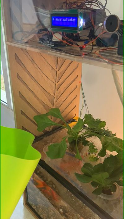
ٌResult
Here are pictures I recently put up to show how I used laser cutting for acrylic. I chose acrylic because it adds beauty with its transparency, and also because it is waterproof.
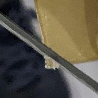
This piece of pot holder was supposed to have curved corners rather than perpendicular angles, because I had to cut these corners in order to be able to fix them on the fish tank.
Vinylcutter
I used vinylcutter to stick the sticker on the front acrylic board, to hide the set of wires inside.