8. Computer Controlled Machining
Group Assignment
To view the group assignment click here.
Individual Assignments
In this assignment, I will design 2D parts of different objects using Fusion 360 so that I can transfer it to reality using “ShopBot” which is a CNC tool.
Chair - Furniture
I used this Tutorial in my design “Flat-pack furniture design”, to design a chair with 3 parts as a joints using the parameters.
Consider the following :
- The width of the entrance to the joints is greater than the width by 0.30 mil
- The entrance to the joints was thicker than the thicker at the level of 0.45 ml
Steps:
-
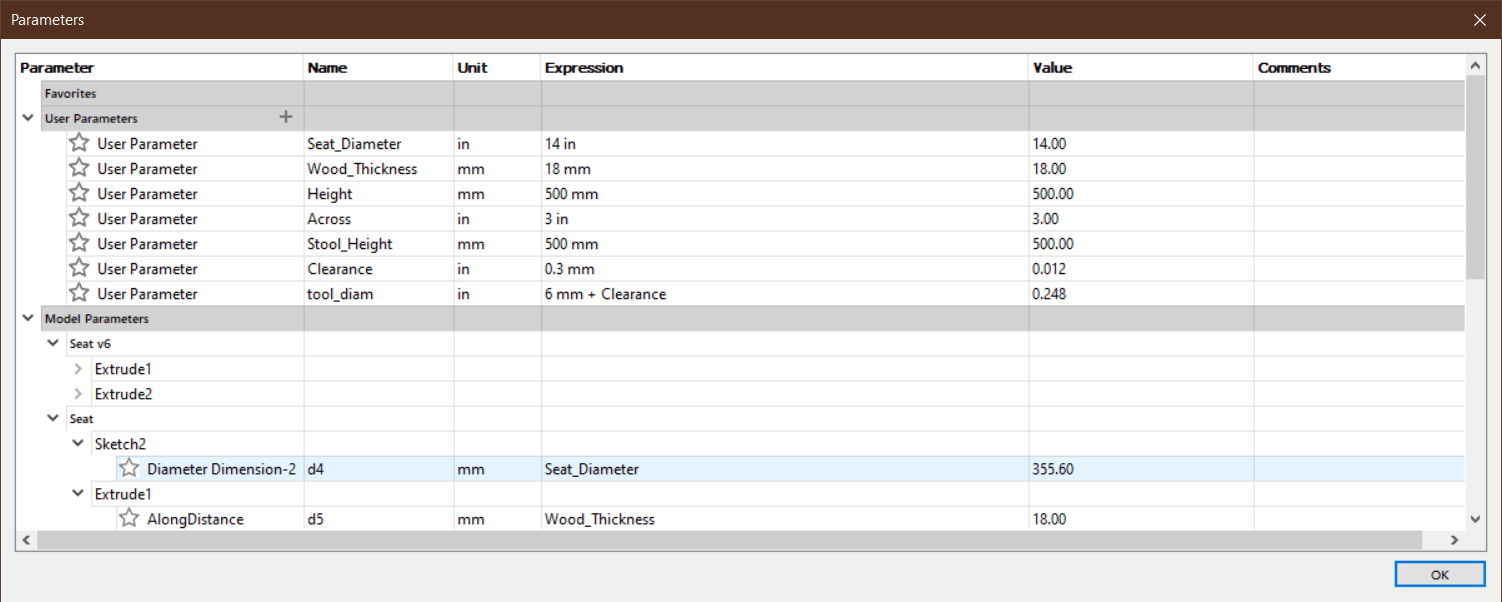
I will use in my design the parameters to be able to change its size whenever I want, so if I change any of these my entire design will update, and because the measurements of the seat parts are connected.
-
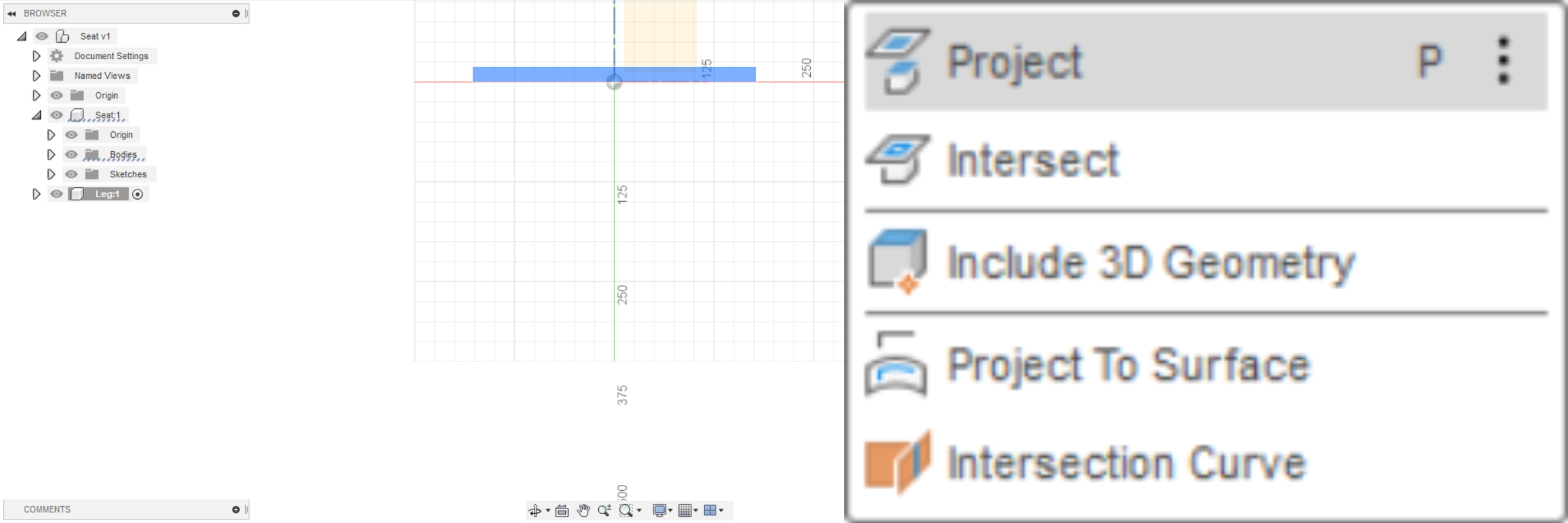
After I finish sketching the part of the seat, I will create a new component for the leg of the chair. To keep interacting with other pieces of geometry, so I will use project feature, to project in some existing geometry.
-
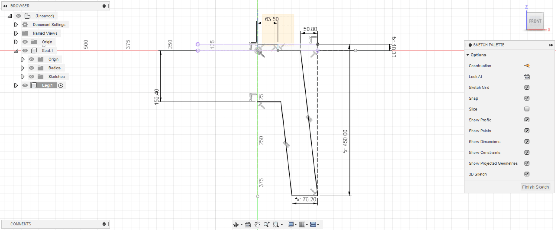
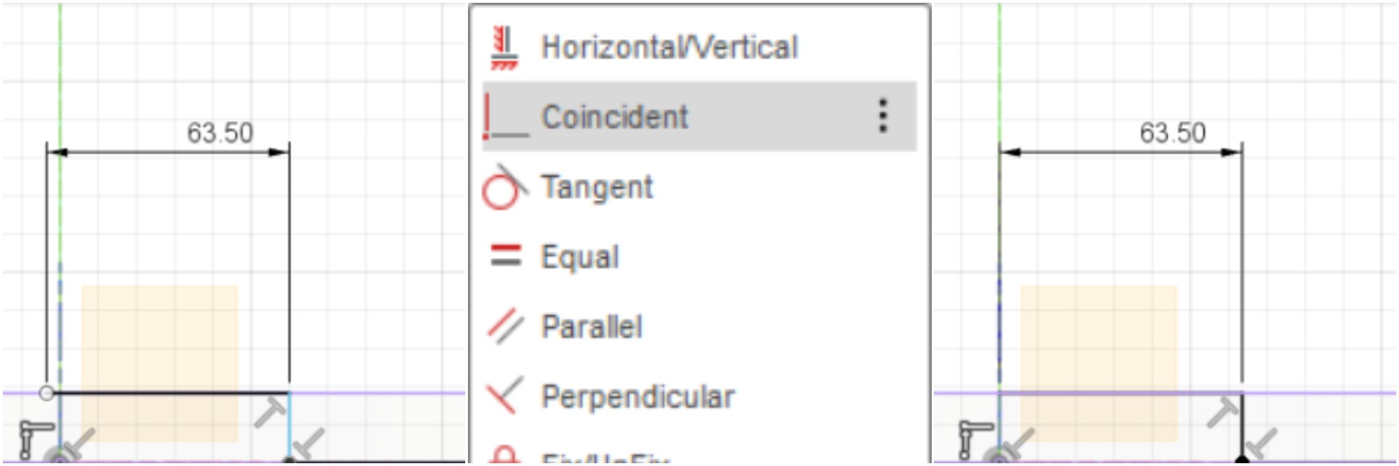
After drawing the legs lines, I set the measurements using the “Dimension” property. What happened is that the sketch has crawled to the left, while I want it to be on the middle line.
-
To solve the problem of sketch crawling without any complications, I used the “Coincident” feature by specifying the lower-left corner with the middle line.
-
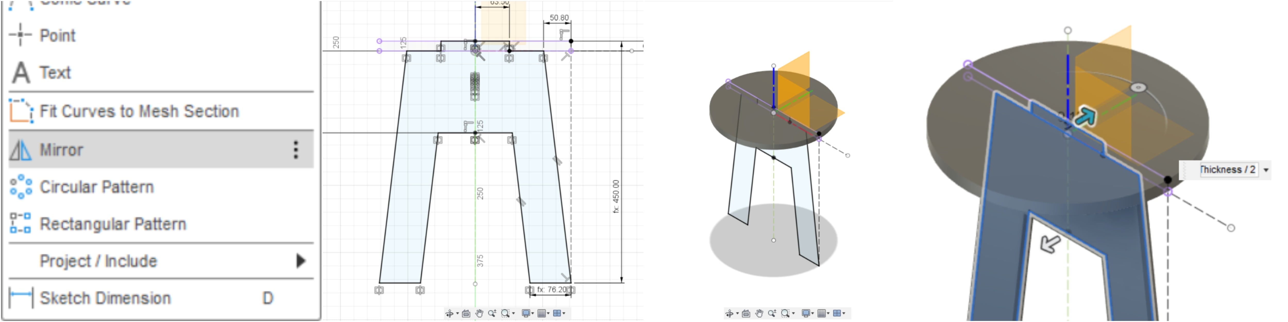
I will choose the mirror feature to show off the second half of this leg. To complete this step I will extrude this sketch. I want the extrude to be in the origin, for that reason I would choose the symmetric direction. Because I want to extrude it with the thickness value, the distance will be equal to the thickness divided by 2.
-
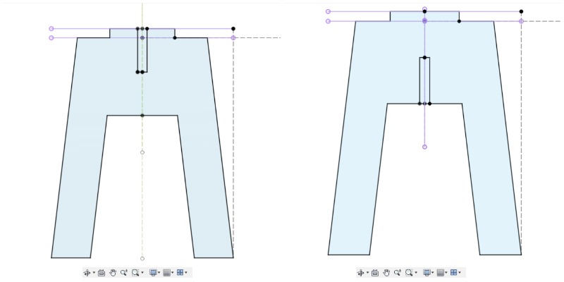
I will repeat the same steps for the first leg to the second leg, and between them a difference of angle equal to 90 degrees.
-
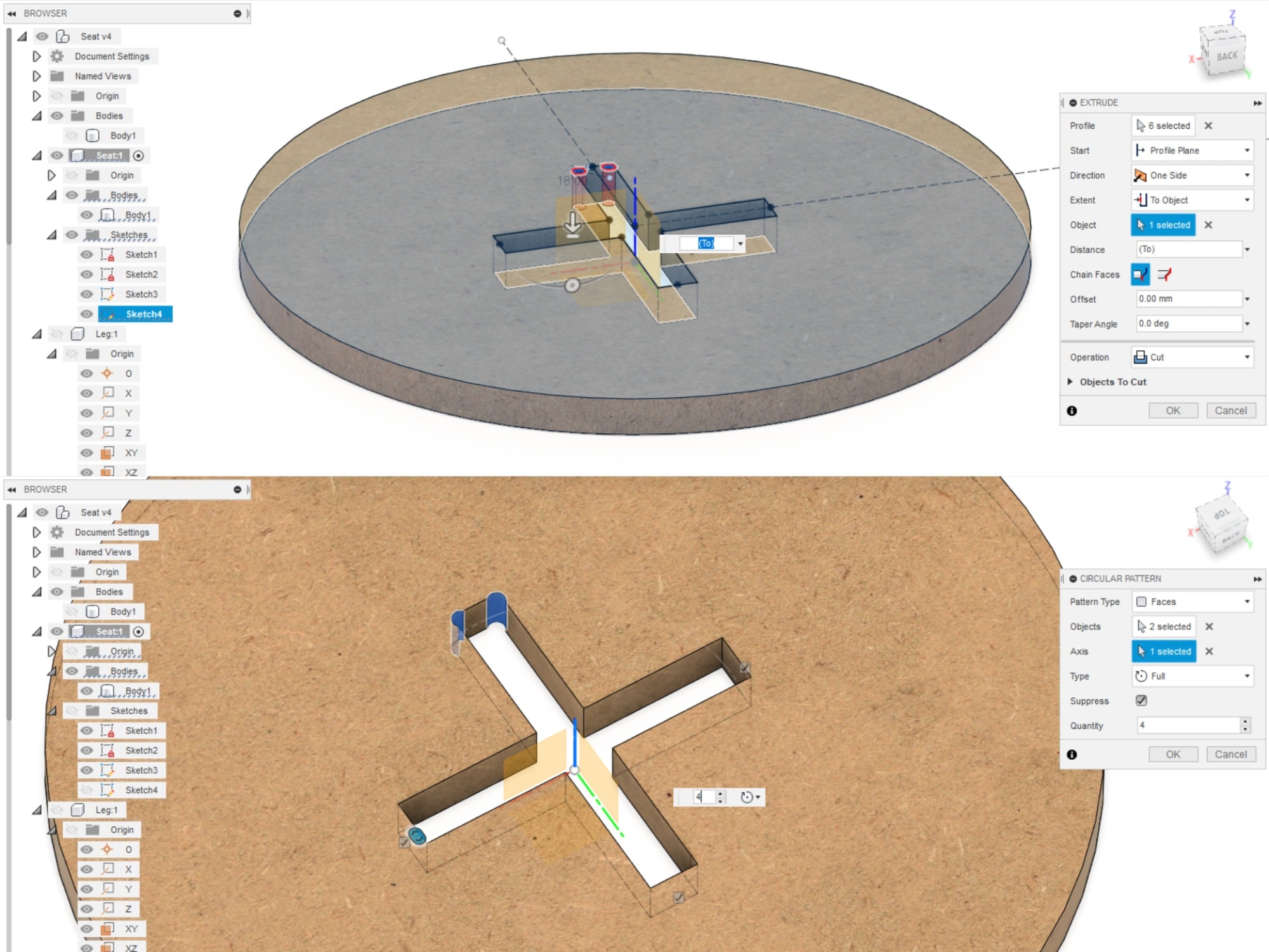
Next, I will make a slit from the top of one of the legs, and a slit from the bottom to the other leg, to be joints. I will extrude them to cut.
-
“Circular Pattern” feature saves a lot of time, I used it in this design twice for the circular seat.
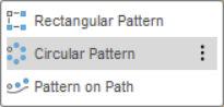
-
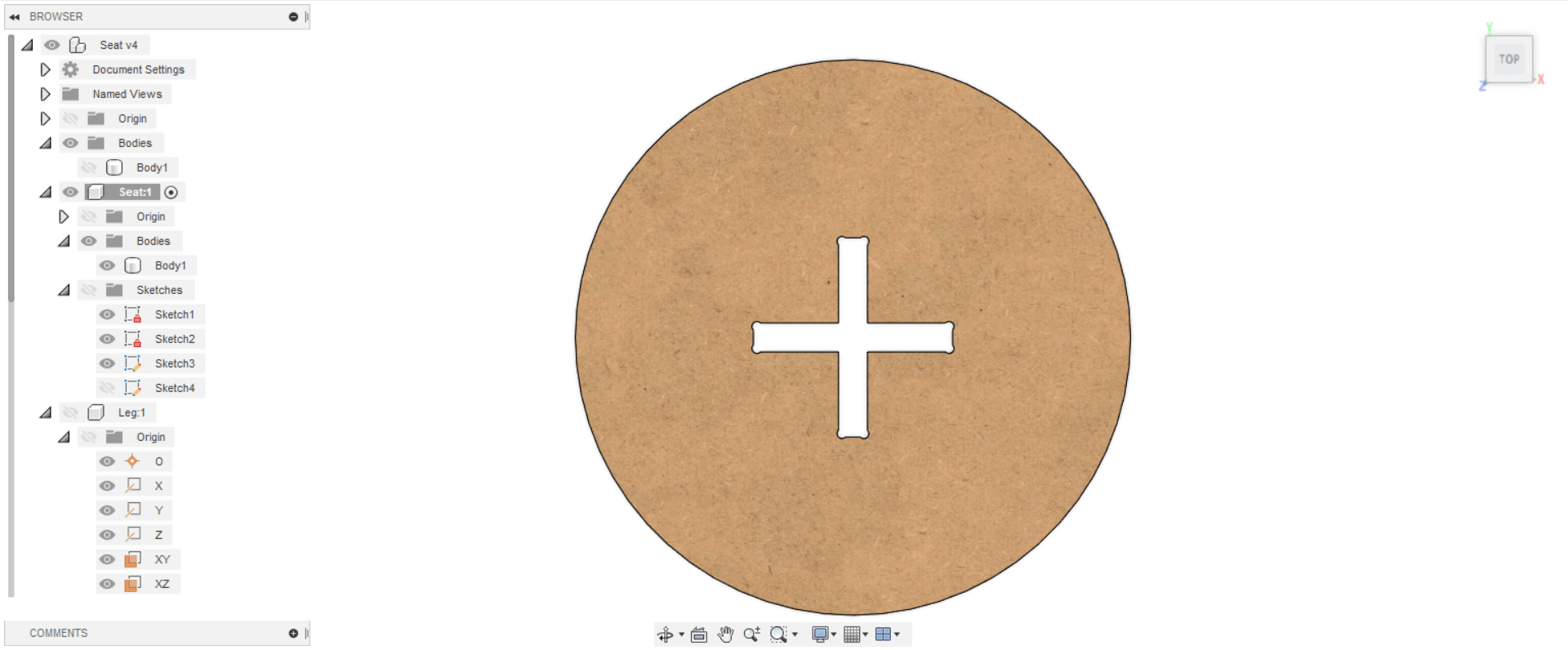
In the center of the seat an opening holding the two legs, a cutout in the seat to all fit together. I will draw one part for one leg, then using this “Circular Pattern” I will repeat it for the rest of the parts.
-
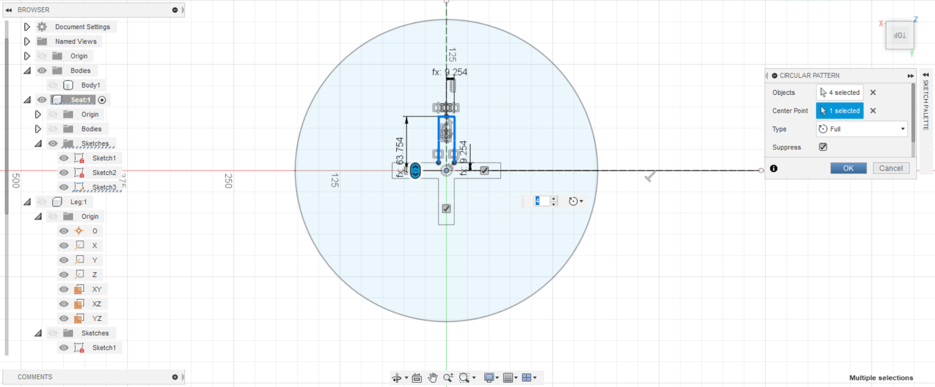
A Dog Bone Joint is a friction fit joint used to join two pieces of sheet material. Typically, dog-bone joints are made using a CNC machine. They are called dog-bone joints because the corners are rounded out and resemble a cartoon-like bone. The reason for the rounded out corners is to remove the extra material that is left by a round bit at the corners.
So to make everything fit together perfectly I will create the dog bone joints in one side of one part of the entire corners, and mirror it to the other side.
-
I’m going to “cut” these two rounded corners, and then using “Circular Pattern” I will cut the rest of the corners to form the dog’s bones.
-
This is how the dog bones form from the top of the seat.
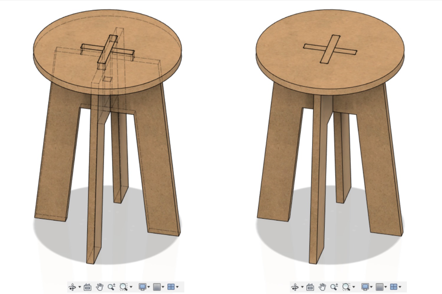
-
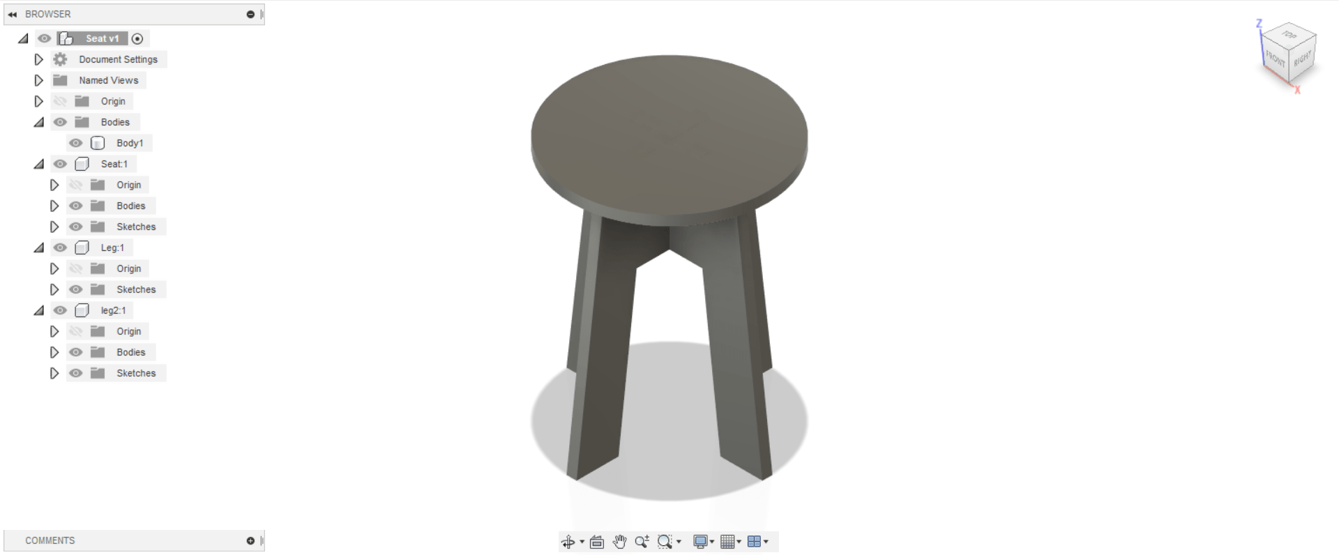
This is the chair ready for milling.
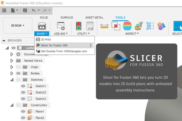
Slicer Lamp
Slicer, is a subsidiary software of Fusion 360, that splits 3D design into 2D. This program can serve this week assignment.
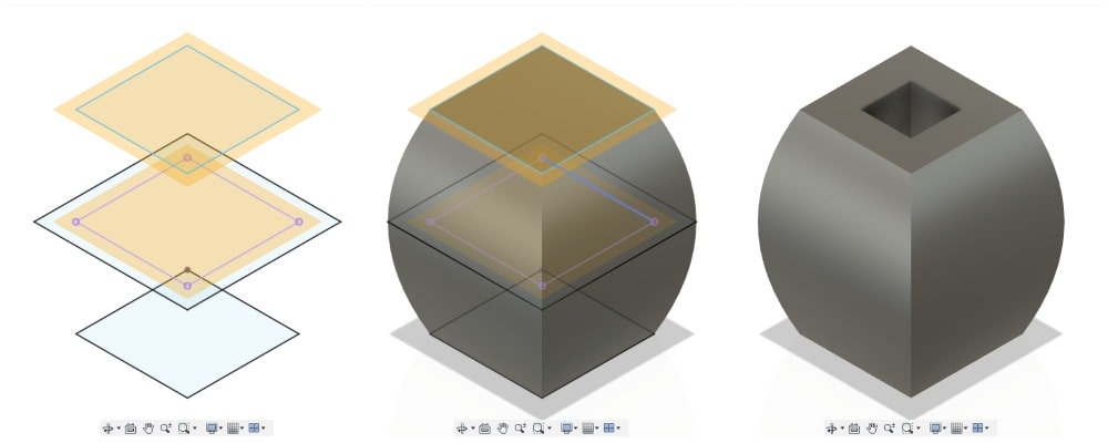
I did this simple design with simple steps, which I sketch it with the “Offset Plane” feature, then I used “Loft” and “Shell”.
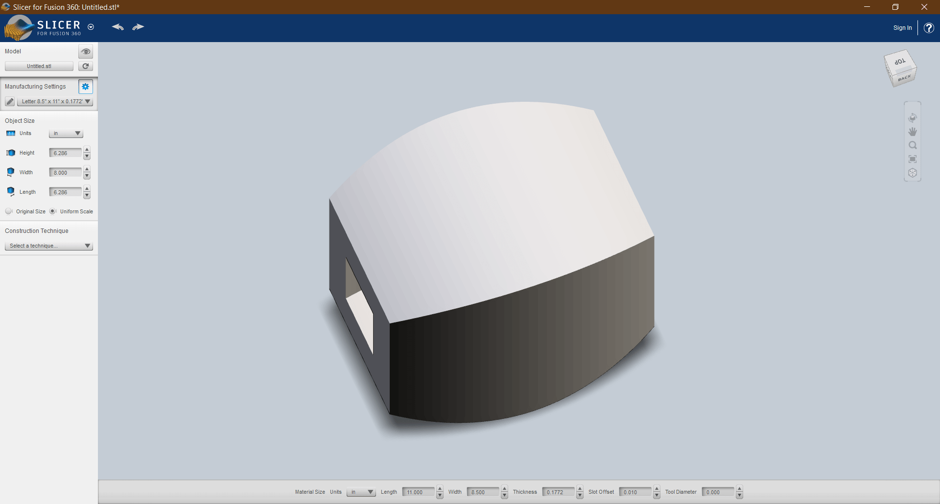
This is the page when you open the model with the slider. The model appears upside down.
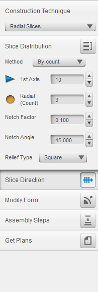
Using the bar on the left of the screen, I can specify the shape of the slice that we want to cut the model with, “Construction Technique”. I chose “Radial Slices”. I can also specify the number of slice I want, “1st Axis” and “Redial (Count)”.
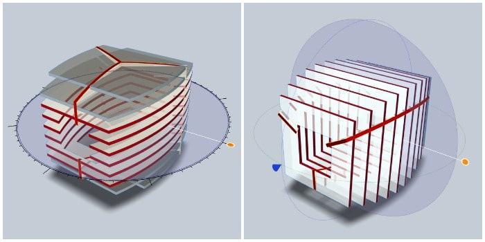
Even when I slised the model it was still upside down, so I adjusted the “Slice Direction” by moving the two axes marked with blue and orange to adjust it.
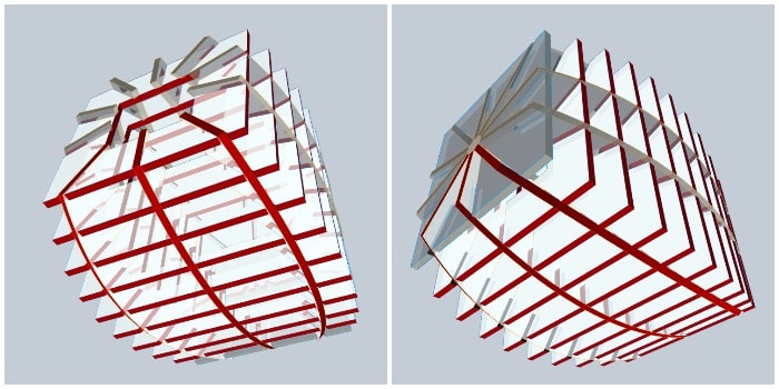
This is how the slised lamp was modified, and the number of slice was determined, from the upper and lower direction. Thus, it can be cut with CNC.
Final Project CNC
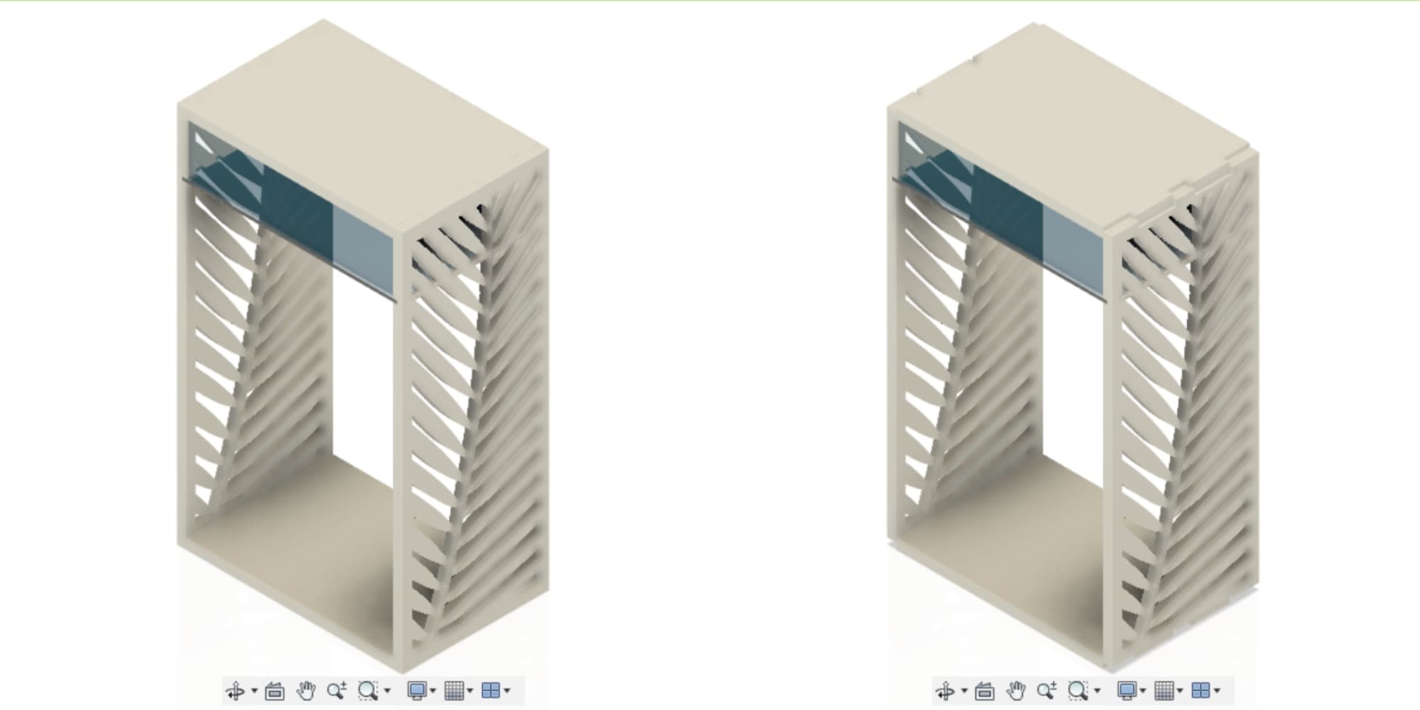
I used this Tutorial in my design CNC Router with Fusion 360, Bookshelf Tutorial, I will design chips as joints using the parameters.
- At first I chose the thickness for wood as “18mm”, but I changed my mind to choose “12mm” because it is most suitable for that. Because I used the parameter, I could change the thickness, but that would cause a lot of errors. So I avoided this step.
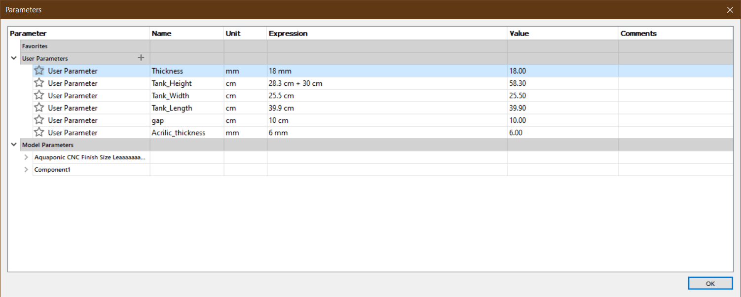 The solution is that when I want to cut the pieces on a CNC machine, I can set the thickness of the wood to 12mm.
The problem now is that the length of the joints will remain 18 mm, according to the old layout.
The solution is that when I want to cut the pieces on a CNC machine, I can set the thickness of the wood to 12mm.
The problem now is that the length of the joints will remain 18 mm, according to the old layout.
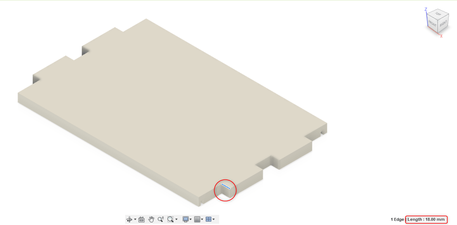 I used the “Offset Face” feature and set the distance as equal to the difference between 18mm and 12mm, which is 6mm, from each end I offset 3mm.
Milling
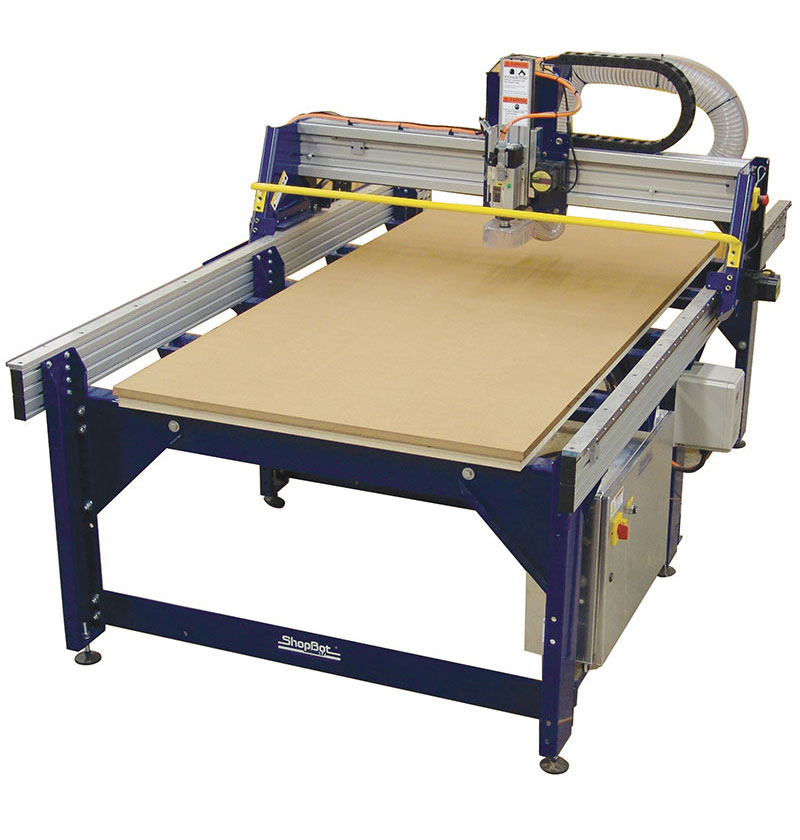
What is CNC?
A CNC (computer numeric control) tool is used for cutting, carving, machining and milling in a variety of materials including wood, mdf, plastics, foams and aluminum.
I will cut my design using ShopBot. ShopBot Tools, like all CNC tools, move a cutter around a big table “x,y,z-axis”. The cutter looks like a drill bit and is spun by a motor called a router or spindle. Unlike a drill bit, a router bit is designed to cut from the sides as well as the tip.
Steps
I followed the same steps listed in “CNC Shopbot” for Fablab Bahrain.
-
Export the design from fusion 360 as “dxf.” files.
-
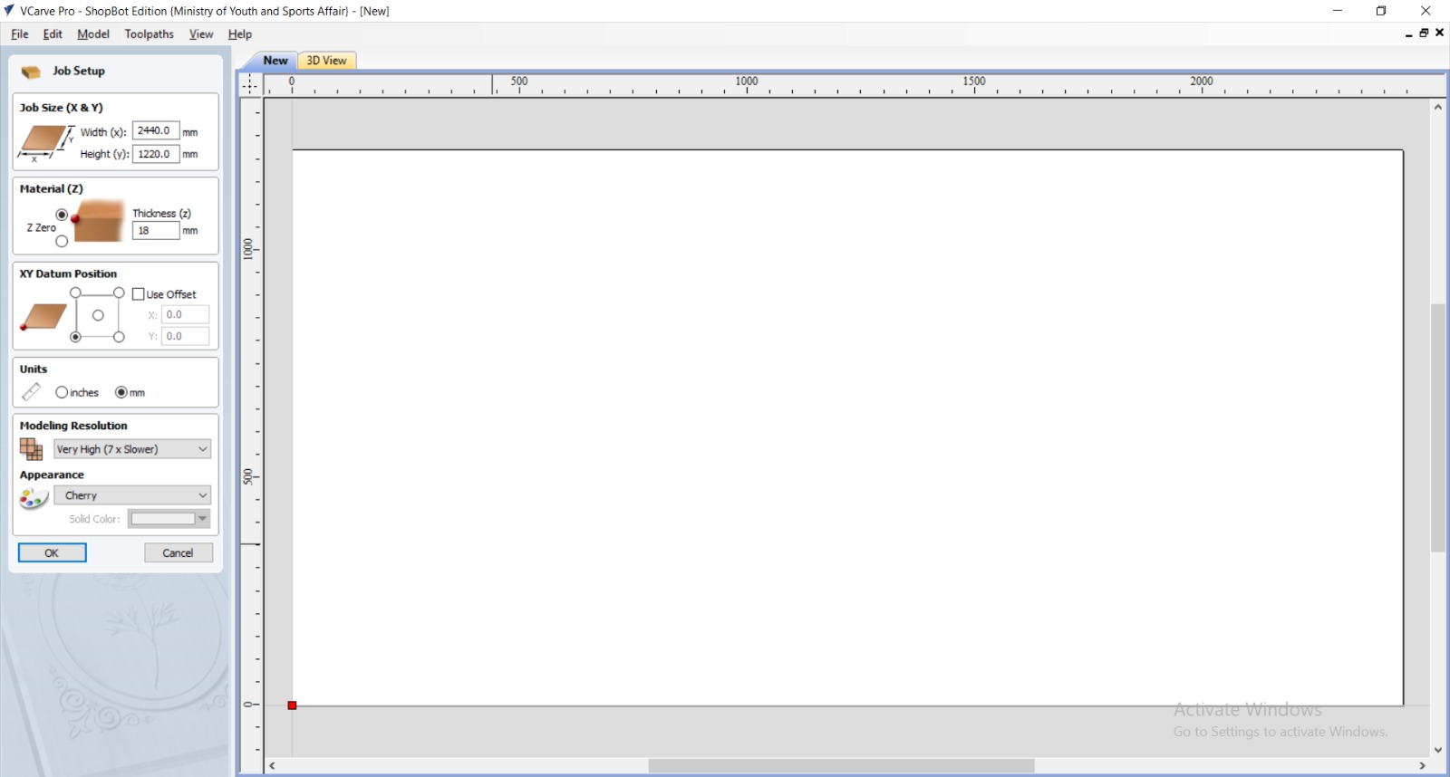
Open “VCarve pro” program, “Create a new file”.
-
Enter the wood dimensions, the wood width and Height from “Jop Size” while the wood thickness from “Material (Z)”.
-
Choose the starting point “Datum Position”.
-
Import the file to the page, “File” > “Import” > “Import Vectors”. Set the design in the appropriate place for it to cut, place it 2 cm from the edges of the wood piece to avoid cutting it on the fixing screw, as well as to avoid cutting it out of bounds. To scale the design use the same tool.
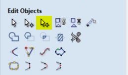
 To move, scale and rotate the file:
-
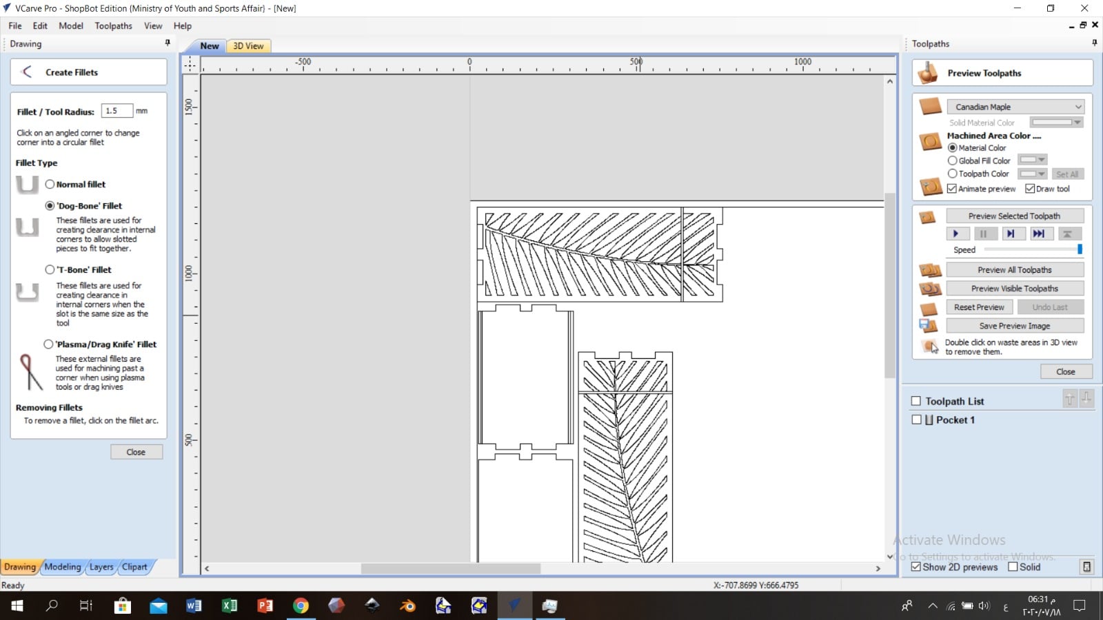
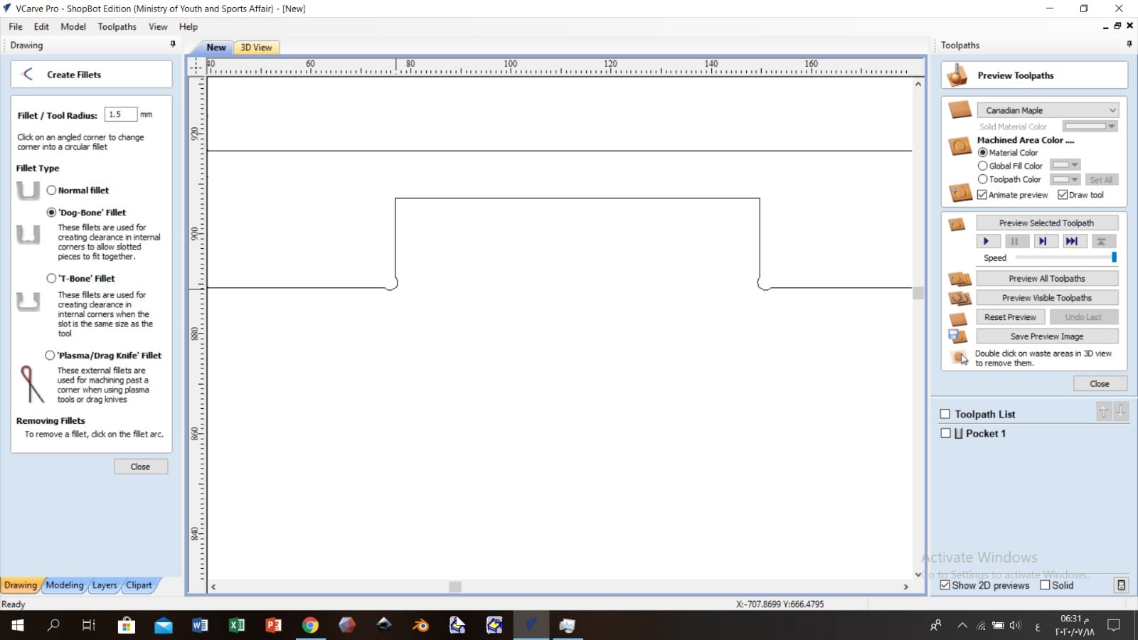
Choose the suitable “Fillet Type”, for me, I chose “Dog-Bone” so that the design does not move easily.
-
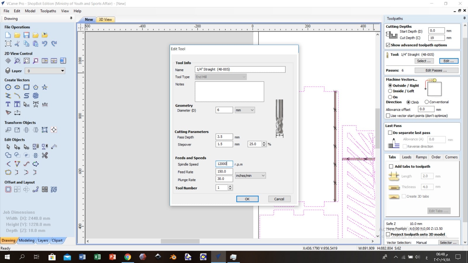
Each material will require different speeds and feeds settings. From “Toolpaths” tab; “Select” the drill bit which is “1/4 Straight” and click “Edit” to adjust the “Spindle Speed” ,”Feed Rate” and the “Plunge Rate”. I followed the numbers listed in the picture, because it based on Fablab Bahrain experiences.
Also from tool path set the cutting depth 1 mm more then the material sheet thickness to make sure that the parts have separated well.
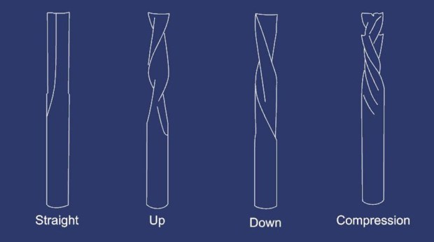
 There are four main types of cutting tools:
-
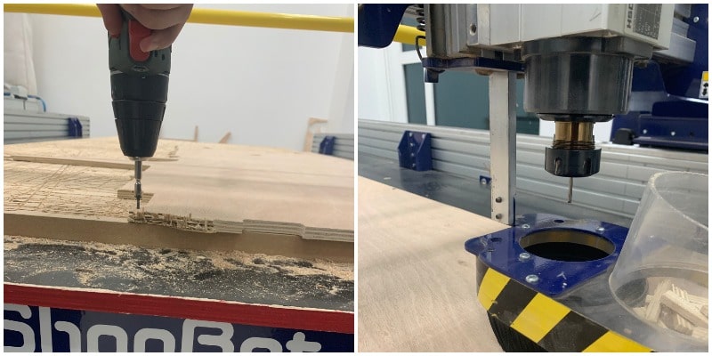
Save the file and import it to “ShopBot” software and set the zero point “Datum Position”; Before that set the wood sheet and fix it with screws, set the drill bit.
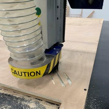
Start Cutting
Stick to wearing protective glasses from chipping off parts of wood, as well as wearing a headset when sitting for a long time in the room so that the ear is not affected by the strong, annoying sound that the machine makes.
Also, by repeating the same previous steps on the other side.
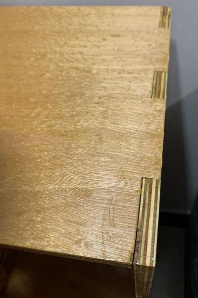
After the cutting was done, I rubbed the wood to remove the excess with “Shami paper”.
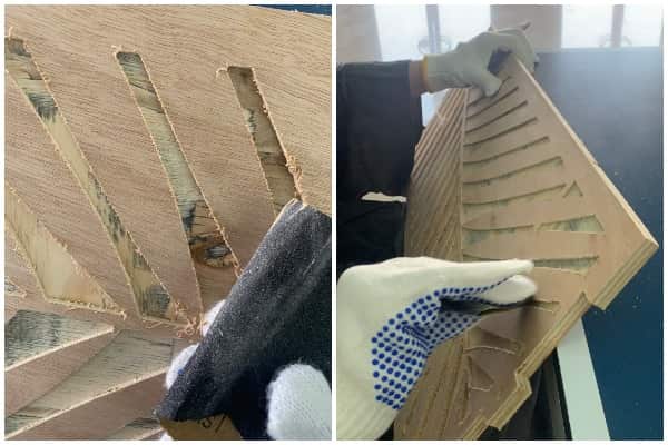
This is the difference between the piece before I rub it and after.
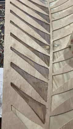
I dyed the blanks in the middle of the leaves a light brown color.
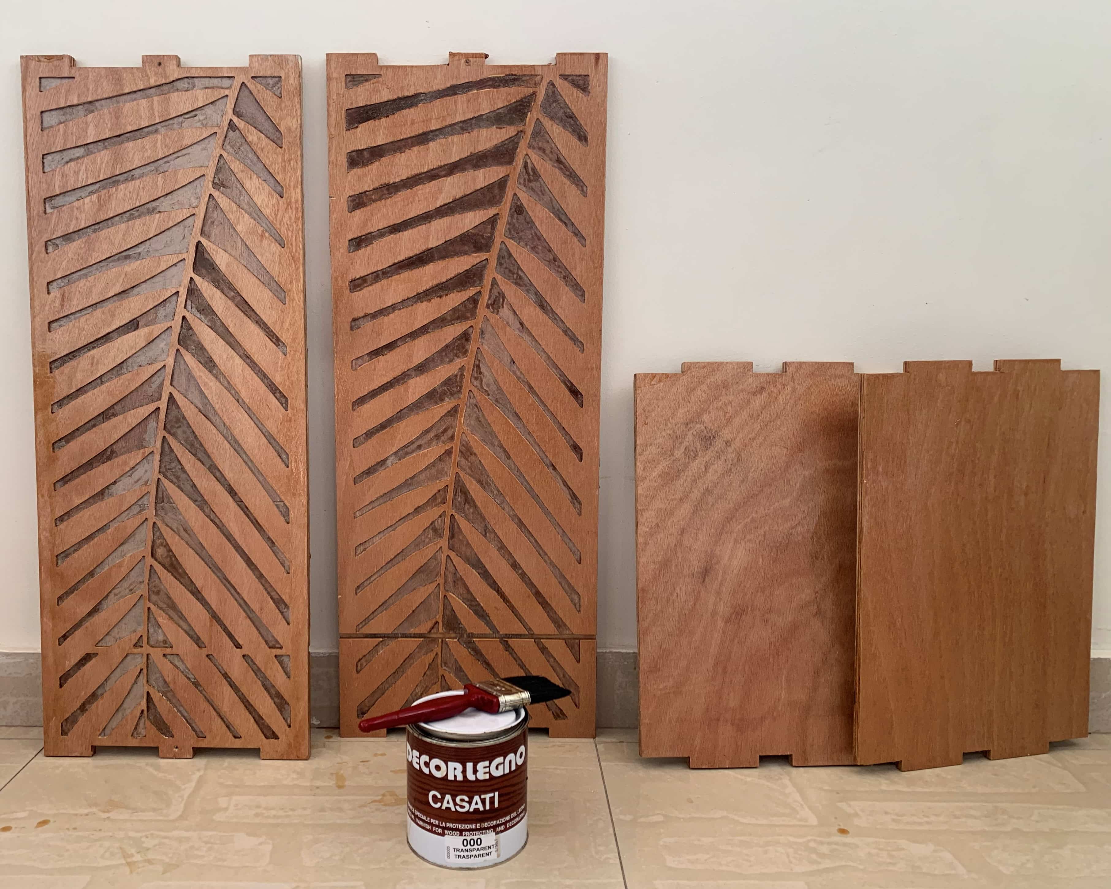
I also wiped the wood with varnish so that the wood does not absorb water and damage it, as the wood will be exposed to water due to the idea of the project.
Result
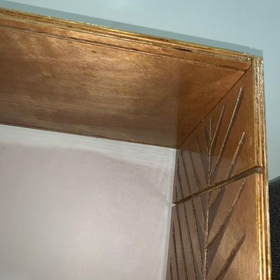
This is what wood looks like after it has been milled, dyed and togethered.
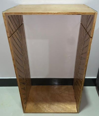
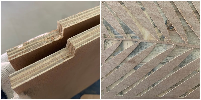
Here is an illustrative picture of the inside pockets I made, which is instead of the joints.
Dog Bones Joints, one of its advantages is that it needs hammering to put together, but dismantling it is difficult.