10. Input Devices
Group Assignment
To view the group assignment click here.
Individual Assignments
Sensors are input devices that record data about the physical environment around it, they do not make judgments, decisions, or control any output devices. This week I am going to use several sensors. I used in that Arduino IDE software.
ATtiny44 PCB with IR Line Tracking Sensor
The requirement in this assignment is to add a sensor to a microcontroller board that we have designed and read it. Recently when I back to the lab, I designed a special board to be used in this assignment to read “IR Module” as well as to use “Vibration Motor” for the Output Device week.
IR Line Tracking Sensor Overview
Before starting the design the PCB, I have to make sure which sensor I am going to use, what were the requirements for it. I think about using the “IR Line Tracking” sensor, the available sensor, and the new to me.
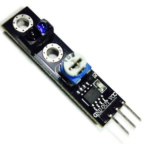
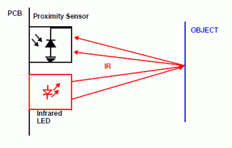
This line tracking sensor has an LED and phototransistor, the LED emits the light and the phototransistor receives the light as an input. The sensor works by detecting reflected light coming from its own infrared LED and by measuring the amount of reflected infrared light.
IR sensor can detect objects directly in front of it, it returns the status of the IR light reflected from a surface as ON or OFF. When the tracking sensor senses detected the LED lights ON, otherwise OFF. IR sensor is useful for detecting something like obstacles that robot walking.
IR Sensor have three Lines
- +5V VCC
- GND
- D0 or OUT (Digital Output)
Sources
- Arduino IR Module Tutorial
- Arduino with IR Sensor
- Arduino lesson – TCRT5000 IR Track Sensor
PCB Design
I started design ATtiny44 PCB with the easy use software EasyEDA, the same software I used to design my final project PCB. To see the steps for using the software, you will find it in the seventh week under “Designing PCB for my Final Project” heading.
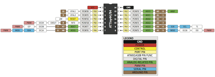
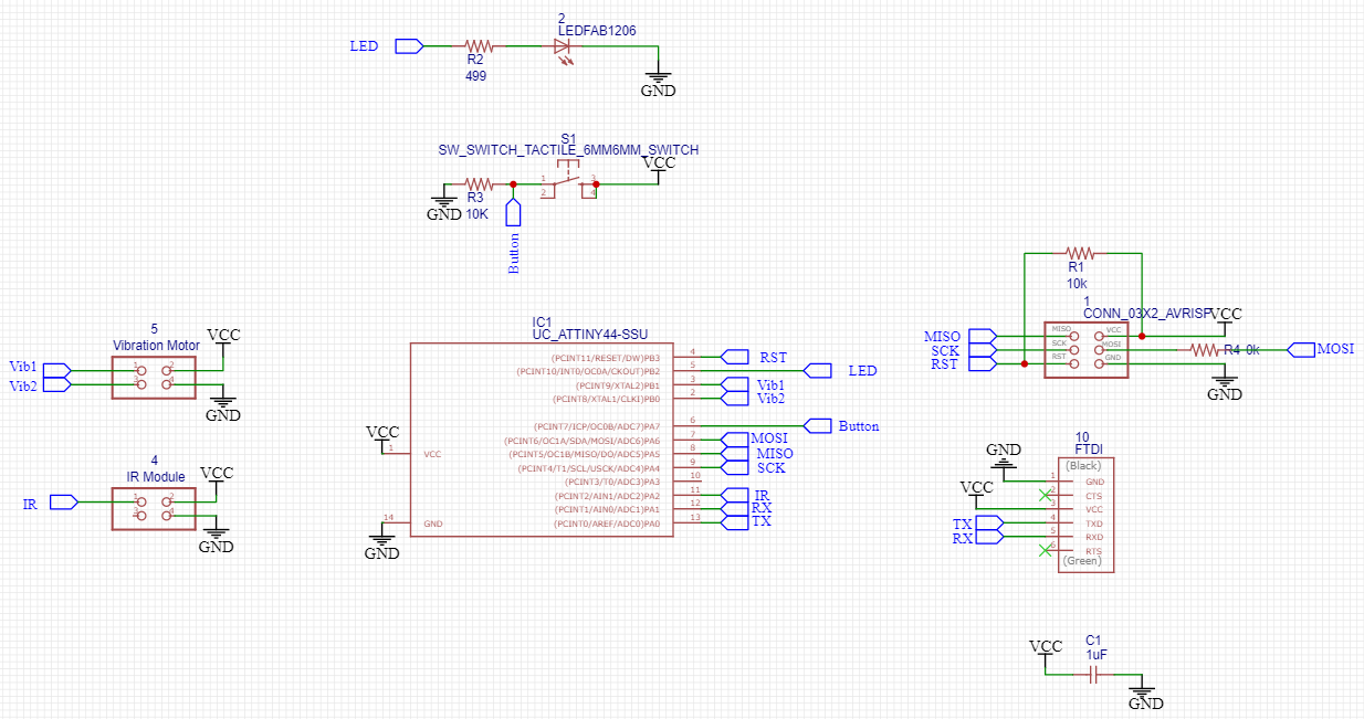
I created a new schematic in EasyEDA and added the components to the schematics editor needed to create the board. For the microcontroller, I decided to chose ATtiny44 because it has enough pins that I need. Also, what I need in the board are the ISP headers which necessary for programming the board, and the FTDI to power the board, as well as to receive and transmit information from and to the microcontroller. I added a button and LED which are very useful in programming. As well as two of four headers, one I will use for the Output Devices Assignment, and the other for this Assignment.
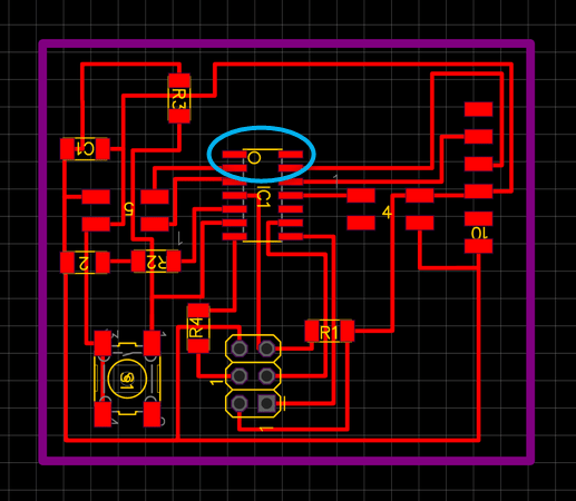
For this input devices assignment, I need to connect three headers for the sensor, GND, and VCC, as well as a digital pin which I choose to connected to the ADC pin “11” of the ATtiny44, which is “2” in Arduino.
This is the schematic circuit shown below.
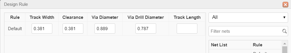
Before start routing the traces, don’t forget to set the appropriate “Design rules”, and also to check the “DRC Errors”.
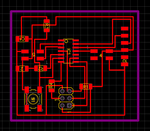
This is the “Design Rule” I set.
Once I had the traces all laid out, I exported them as “.svg” files to start milling, as the “Top layer”, “Holes”, “Outlines” each in a file. That is to prepare for milling.
Milling and Soldering
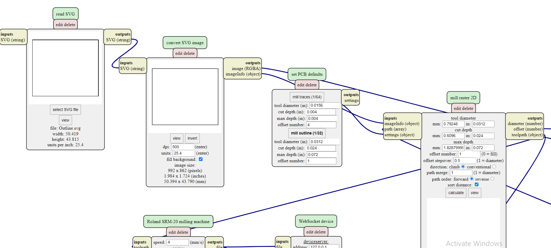
I saved the PCB file as a “.svg” file to open it in MODS, so I could send the job to “VPanel for SRM-20” to start milling. I refer to Electronics production week to recall the steps.
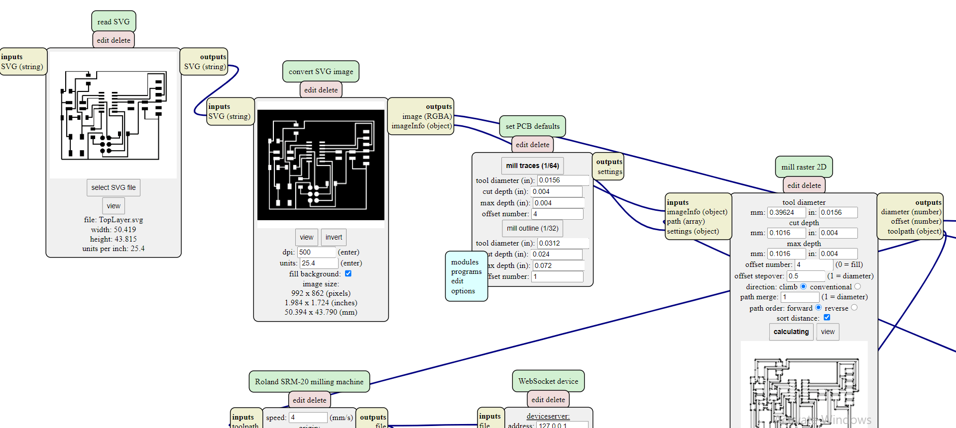
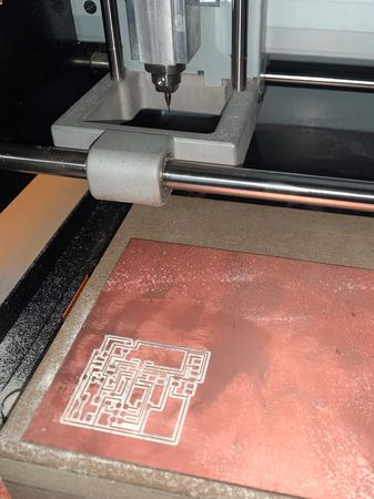
Here shows that when the thickness of the outline is small “0.381 m”, as I set it, the “1/32” milling tool couldn’t see. So we have to set what approximate 1/32 inch which is equal to 0.794mm.
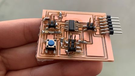
This is a picture after finished milling the top layer, and changing the milling tool from “1/64” to “1/32”.
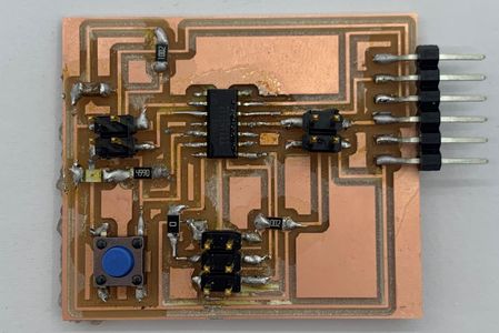
After I soldered each component I check continuity with the multimeter, no apparent shorts. I soldered the components in place.
Programming
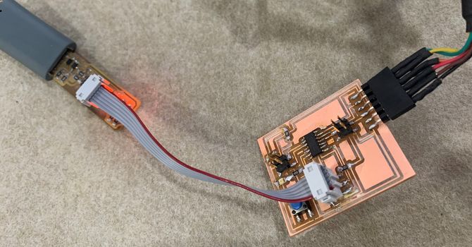
I connected the board ISP header to the FabISP, and connected the board to the FTDI cable to get power.
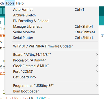
I will use Arduino IDE for programming, and this is my board tools settings. The ATtiny44 has an internal clock that runs at 8 MHz, and I used the “USBtinyISP” to program it.
Problem
At first, I tried to upload the Blink Code to test the board, but it is not uploading, an error! It looks like the defect from the board that I made.
To make sure of this, I used a multimeter, I want to make sure that each of the ISP header for both of the USBtinyISP and the ATtiny44 PCB connected or not. For example MOSI to MOSI, RST to RST, etc. Here the problem appeared, that the GND and Vcc are not connected.
I checked my board and it appears that I didn’t connect ATtiny44 microcontroller GND and Vcc with the other traces, while I connected them in the schematic!
It became clear to me recently that the reason was that I had not used “wire” to connect the VCC and GND to ATtiny44.
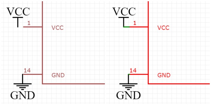
So I solder a jumper wire to connect the VCC and GND to the nearest trace.
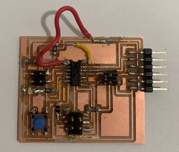
After this was successful, I connected the sensor to the headers on the board.
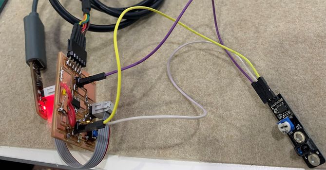
I uploaded a code to the board, which sends “detected!!!!!” to the serial monitor when an object is approaching the sensor, as well as opening the LED for the sensor. As for when there is no object near the sensor, it sends “nothing detected”.
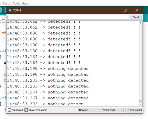
This video demonstrates the code working.
Source Code
int IRSensor = 2; // connect ir sensor to arduino pin 2
int LED = 8; // conect Led to arduino pin 8

#include <SoftwareSerial.h>

SoftwareSerial mySerial(1, 0); // RX, TX


void setup()
{
  mySerial.begin(9600);

  pinMode (IRSensor, INPUT); // sensor pin INPUT
  pinMode (LED, OUTPUT); // Led pin OUTPUT
}

void loop()
{
  int statusSensor = digitalRead (IRSensor);

  if (statusSensor == 1){
    digitalWrite(LED, LOW); // LED LOW
      mySerial.println("nothing detected");
  }
  else
  {
    digitalWrite(LED, HIGH); // LED High
    mySerial.println("detected!!!!!");

  }

}
Files
- I/O ATtiny44 PCB Schematic sch.
- I/O ATtiny44 PCB brd.
- Toplayer for Milling - I/O ATtiny44 svg.
- Hole for Milling - I/O ATtiny44 svg.
- Outline for Milling - I/O ATtiny44 svg.
- IR Module Source Code ino.
Measuring Temperature Using TMP36
Here I will measure the temperature using TMP36 temperature sensor, the sensor will send data to my Attiny44 board I have designed in Electronics Design week to read it.
About TMP36 Sensor
Overview
The TMP36 are low voltage, precision centigrade temperature sensors. They provide a voltage output that is linearly proportional to the Celsius (centigrade) temperature. The TMP36 do not require any external calibration to provide typical accuracies of ±1°C at +25°C and ±2°C ove
r the −40°C to +125°C temperature range.
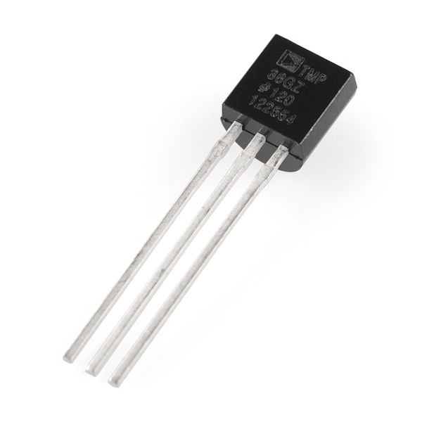
Pin Definitions
The IC has just 3 pins, 2 for the power supply and one for the analog output. The output pin provides a voltage output that is linearly proportional to the celsius (centigrade) temperature. Below is the pinout of the TMP36 IC.

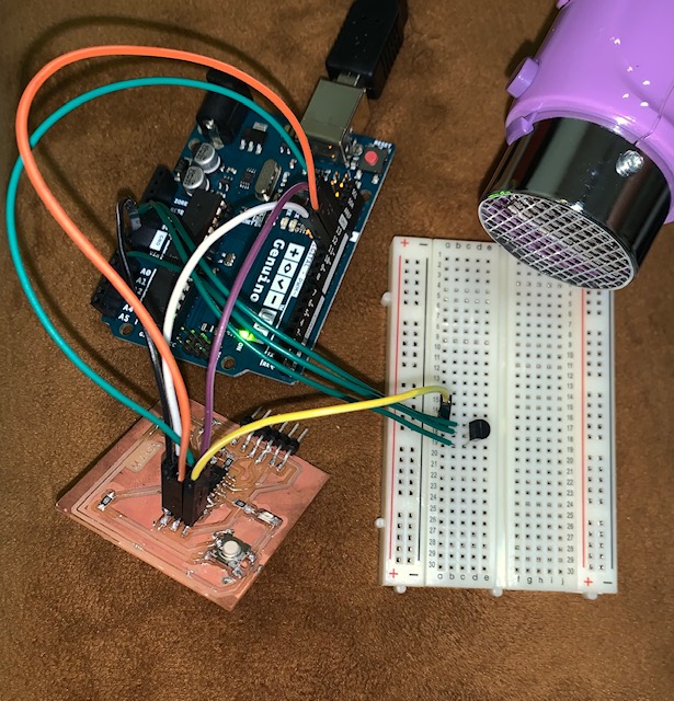
Schematics
I connected the sensor to the Arduino this way, and I added my board the way I connected it to the previous week.

Code
//TMP36 Pin Variables
int sensorPin = 0; //the analog pin the TMP36's Vout (sense) pin is connected to
                        //the resolution is 10 mV / degree centigrade with a
                        //500 mV offset to allow for negative temperatures

/*
 * setup() - this function runs once when you turn your Arduino on
 * We initialize the serial connection with the computer
 */
void setup()
{
  Serial.begin(9600);  //Start the serial connection with the computer
                       //to view the result open the serial monitor
}

void loop()                     // run over and over again
{
 //getting the voltage reading from the temperature sensor
 int reading = analogRead(sensorPin);

 // converting that reading to voltage, for 3.3v arduino use 3.3
 float voltage = reading * 5.0;
 voltage /= 1024.0;

 // print out the voltage
 //Serial.print(voltage); Serial.println(" volts");

 // now print out the temperature
 float temperatureC = (voltage - 0.5) * 100 ;  //converting from 10 mv per degree wit 500 mV offset
                                               //to degrees ((voltage - 500mV) times 100)
 Serial.print(temperatureC); Serial.println(" degrees C");

 // now convert to Fahrenheit
 //float temperatureF = (temperatureC * 9.0 / 5.0) + 32.0;
 //Serial.print(temperatureF); Serial.println(" degrees F");

 delay(2000);                                     //waiting a second
}
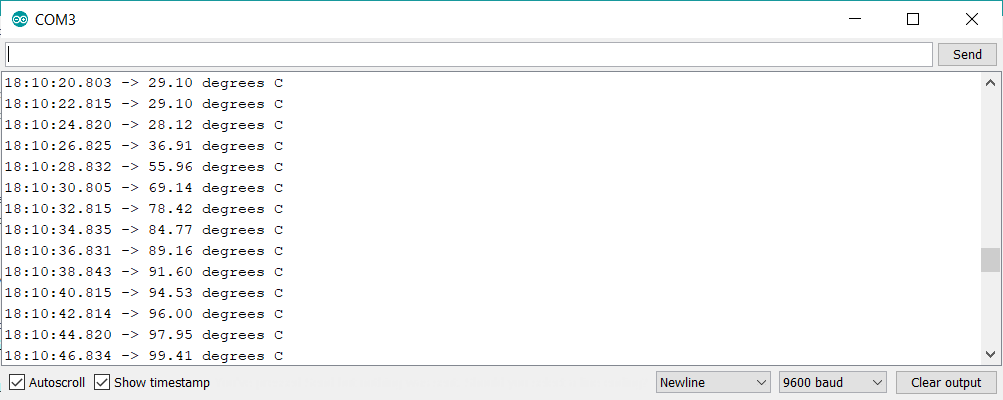
Readings
I expose the sensor to a heat source to see its effect, as well as readings that indicate the sensor’s effectiveness. As I mentioned earlier, this sensor can detect the temperature up to 125°C.
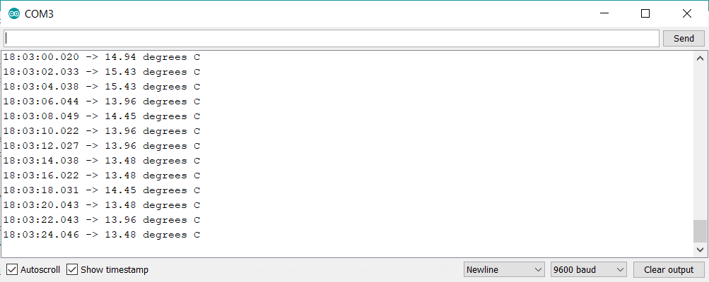
I also put on the sensor an ice cube wrapped in tissue paper, to see the low-temperature effect on the sensor.
Useful links
Measuring Humidity and Temperature Using DHT11
In this part, we will see that DHT11 sensor can measure humidity and temperature at the same time.
About DH11 and DH22 Sensors
Overview
These sensors are very popular for electronics hobbyists because there are very cheap but still providing great performance. Here are the main specifications and differences between these two sensors:
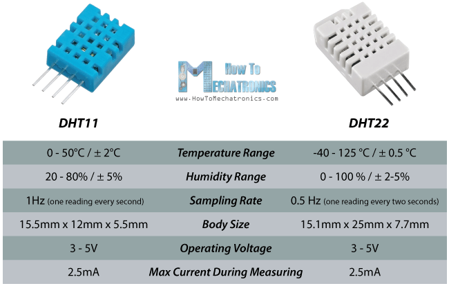
The DHT22 is the more expensive version which has better specifications.
DHT Pinout
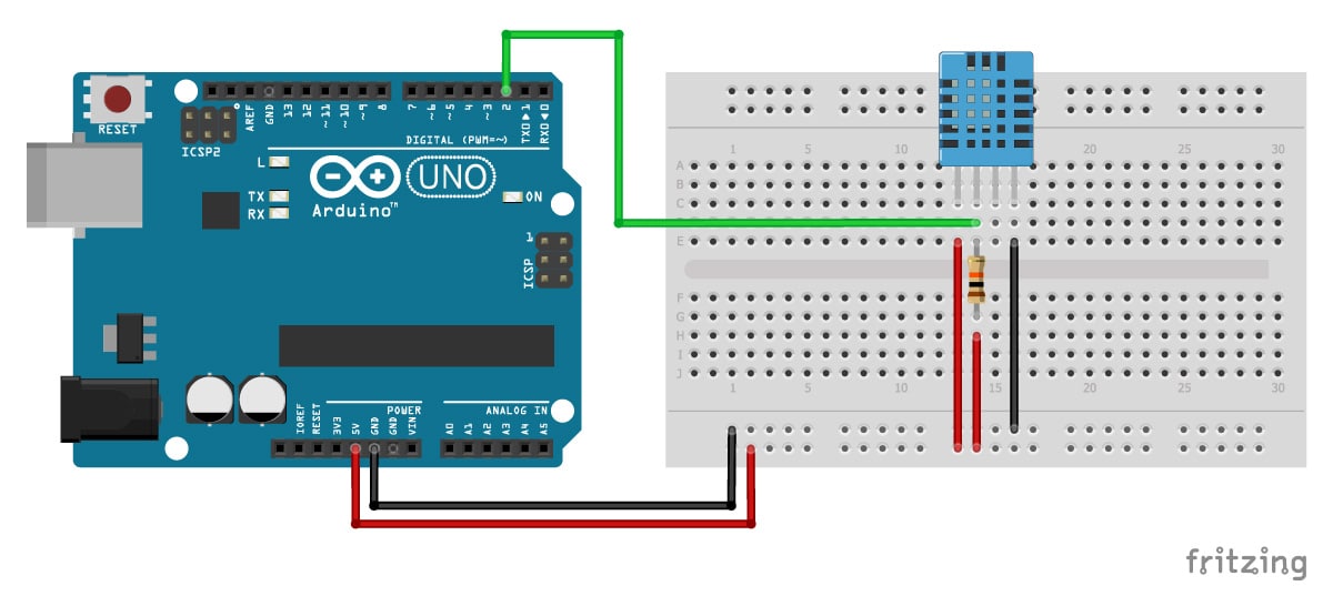
DHT sensors have four pins as shown in the following figure. However, if you get your DHT sensor in a breakout board, it comes with only three pins and with an internal pull-up resistor on pin 2.
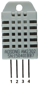
The following table shows the DHT22 and DHT11 pinout. When the sensor is facing you, pin numbering starts at 1 from left to right.
| DHT pin | Description |
|---|---|
| 1 | 5 V |
| 2 | Any digital GPIO; also connect a 10k Ohm pull-up resistor |
| 3 | Don’t connect |
| 4 | GND |
Schematics
I connect the sensor this way:
Library
DHT-sensor-library-master.zip; You can install the library by going to “Sketch” >> “Include Library” >> “Add .ZIP Library” in the Arduino IDE.
Code
/* Arduino example code for DHT11, DHT22/AM2302 and DHT21/AM2301 temperature and humidity sensors. More info: www.makerguides.com */

// Include the libraries:
#include <Adafruit_Sensor.h>
#include <DHT.h>

// Set DHT pin:
#define DHTPIN 2

// Set DHT type, uncomment whatever type you're using!
#define DHTTYPE DHT11   // DHT 11
//#define DHTTYPE DHT22   // DHT 22  (AM2302)
//#define DHTTYPE DHT21   // DHT 21 (AM2301)

// Initialize DHT sensor for normal 16mhz Arduino:
DHT dht = DHT(DHTPIN, DHTTYPE);

void setup() {
  // Begin serial communication at a baud rate of 9600:
  Serial.begin(9600);

  // Setup sensor:
  dht.begin();
}

void loop() {
  // Wait a few seconds between measurements:
  delay(2000);

  // Reading temperature or humidity takes about 250 milliseconds!
  // Sensor readings may also be up to 2 seconds 'old' (its a very slow sensor)

  // Read the humidity in %:
  float h = dht.readHumidity();
  // Read the temperature as Celsius:
  float t = dht.readTemperature();
  // Read the temperature as Fahrenheit:
  float f = dht.readTemperature(true);

  // Check if any reads failed and exit early (to try again):
  if (isnan(h) || isnan(t) || isnan(f)) {
    Serial.println("Failed to read from DHT sensor!");
    return;
  }

  // Compute heat index in Fahrenheit (default):
  float hif = dht.computeHeatIndex(f, h);
  // Compute heat index in Celsius:
  float hic = dht.computeHeatIndex(t, h, false);


  Serial.print("Humidity: ");
  Serial.print(h);
  Serial.print(" % ");
  Serial.print("Temperature: ");
  Serial.print(t);
  Serial.print(" \xC2\xB0");
  Serial.print("C | ");
  Serial.print(f);
  Serial.print(" \xC2\xB0");
  Serial.print("F ");
  Serial.print("Heat index: ");
  Serial.print(hic);
  Serial.print(" \xC2\xB0");
  Serial.print("C | ");
  Serial.print(hif);
  Serial.print(" \xC2\xB0");
  Serial.println("F");
}
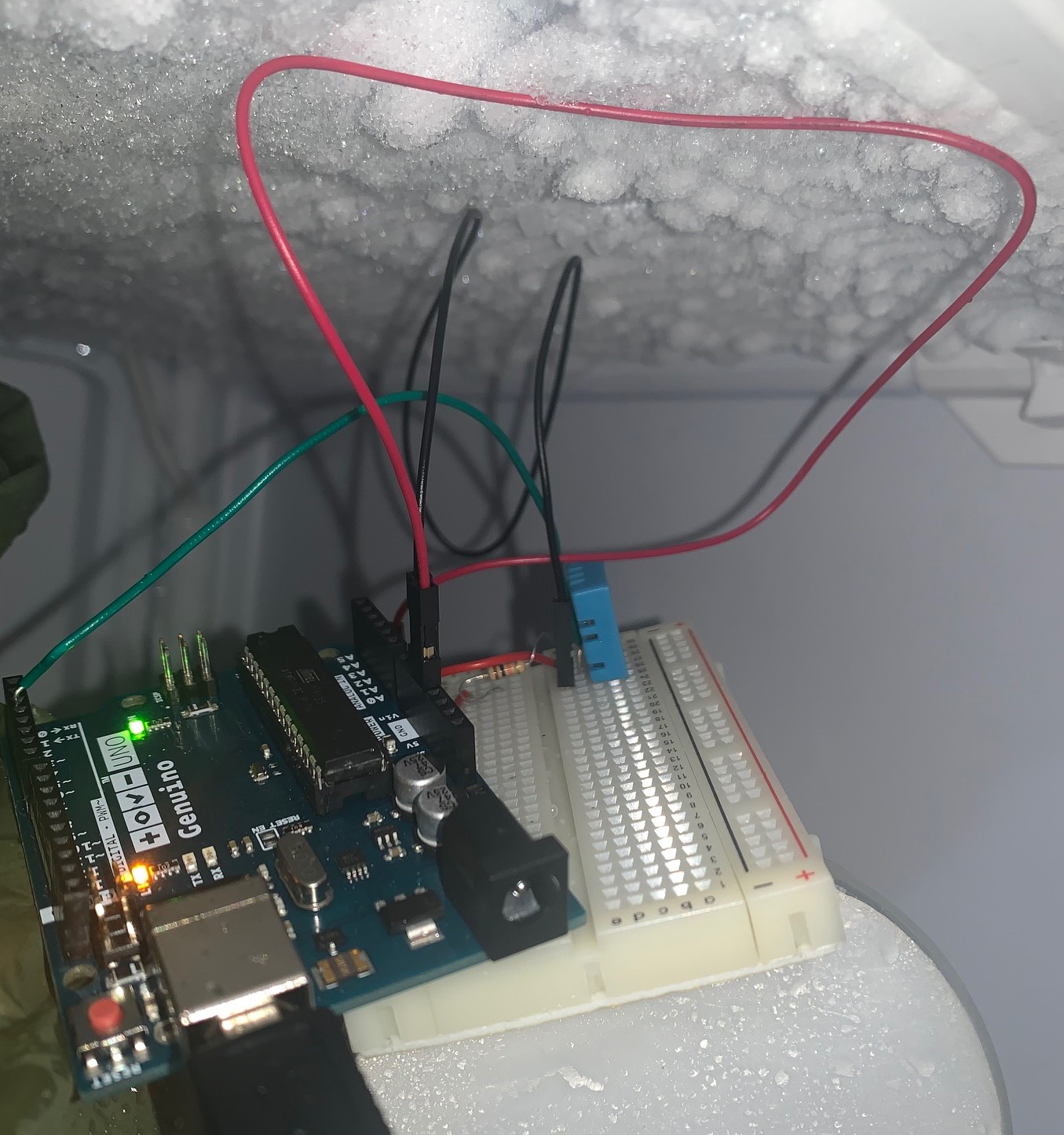
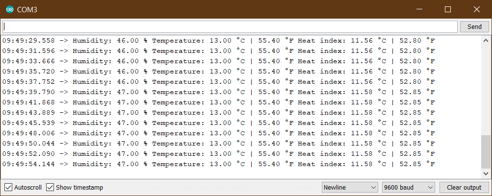
Readings
I put the sensor in the freezer because I think it is an ideal place to test the sensor reading for temperature and humidity together. Humidity is the presence of water vapor in the air (or any other gas). In normal room air, there is typically about 1% water vapor.
Useful links
- How to use DHT11 and DHT22 Sensors with Arduino
- Youssef BOUALI Fabacademy2015
- DHT11 & DHT22 Sensors Temperature and Humidity Tutorial using Arduino
- Complete Guide for DHT11/DHT22 Humidity and Temperature Sensor With Arduino
- Beginner’s guide to humidity measurement
My Final Project Input Sensors
In my project, I used three sensors, each with its own function to operate the system.
- Humidity of Soil
- Water Level “HC-SR04 Ultrasonic”
- Light Sensor
The ultrasound will read the height of the water in the aquarium. If the height of the water is less than the required rate, we will hear a sound from a speaker to alert, and “NO WATER :(” phrase will also appear on an LCD screen, which requires adding more water to the aquarium.
After adding the water, or when the height of the water is appropriate, it will move to the next step, which is spraying the plants from the aquarium water, or in other words, running the pump to spray the plants. The pump will turn on only when the humidity is less than 45% in the plant’s environment.
The third step is to read the light sensor. If the lighting that the plant is exposed to is insufficient, the light will turn on, and if it is sufficient, it will turn off.
Also no matter how low the humidity of the plant’s surroundings is if the water level below normal.
Source Code
This is the section of code for taking sensor readings and displaying them on the LCD screen. To see the code in full, go to the previous week.
//===========================================================================
//  Water Level Sensor
//===========================================================================

  double readDistance(bool display) {
    double temp = 0;

    for(int i=0; i<10; i++) {
      temp += distanceSensor.measureDistanceCm();
      delay(20);
    }

    temp/=10;

    if(display) LCD_PRINT("DISTANCE : CM", String(temp));
    return temp;
  }

//===========================================================================
//  Soil Moisture Sensor
//===========================================================================

  int readMoisture(bool display) {
    int temp = 0;

    for(int i=0; i<10; i++) {
      temp += map(analogRead(SOIL_SENSOR),550,0,0,100);
      delay(20);
    }

    temp/=10;

    if(display) LCD_PRINT("Moisture : %", String(temp));
    return temp;
  }

//===========================================================================
//  Natural Light Sensor
//===========================================================================

  int readLight(bool display) {
    int temp = 0;

    for(int i=0; i<10; i++) {
      temp += analogRead(LIGHT_SENSOR);
      delay(20);
    }

    temp/=10;


    if(display) LCD_PRINT("INTENSITY :", String(temp));
    return temp;
  }