15. Interface and Application Programming
Group Assignment
To view the group assignment click here
Individual Assignments
When we build electronics projects, we need a medium to display output values. For this assignment, I will interface the distance measured by ultrasonic by “Processing”. In the other part of I will interface an LCD in the alarm system.
HC-SR04 Ultrasonic
Here I am going to send data from Arduino to “Processing” over the serial port, to display ultrasonic measurement in new way. Start with downloading Processing by clicking here and follow these steps:
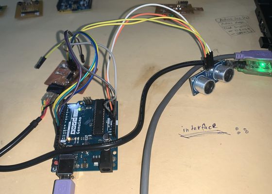
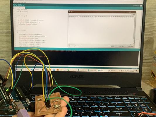
Here I am using Arduino UNO to provide power to the ultrasonic, and to program ATtiny44 board, also I am using here FTDI cable for serial communication as I will explain leter.
Arduino and Source Code
-
Set up the Arduino after connecting it, by uploading the “ArduinoISP” code to it.
-
Connect the ISP headers for the ATtiny44 PCB with Arduino pins, exactly as in Embedded Programming Weeek.
-
Also, follow the same steps in setting the board “tools” in Embedded Programming Weeek and upload the following code :
Arduino Code
“setup()” method where we set up our program. Here, we’re using it to make serial communication from the Arduino to our computer at a baud rate of 9600.
“loop()” method, used to repeat over and over as long as our program is running. In our code it will constantly take the distance reading and send it to the “Serial Monitor”. mySerial.println(distance);
Here is the code, I am going to connect ATtiny44 FTDI “RX” and “TX” to Arduino pins, “PA1” and “PA0” respectively. After uploading the code I am going to connect “Trig” pin to “MISO”, and the “Echo” pin to “MOSI” as I will explain later. It is possible to connect two jumper wires from “RX” and “TX” to the Arduino, and it is also possible to dispense from that by using the FTDI cable.
There is a difference between using jumper wires and the FTDI cable. When uploading the code using the jumper wires “COM3”, we separate the wires from one of the board because it does not accept uploading the code, and when we see the serial monitor, we do not change the port “COM3”. When using the FTDI cable, there is no need to remove it during uploading the code, but we use “COM3” before downloading the code, and “COM5” after downloading it to see the serial monitor.
// defines pins numbers
const int trigPin = PA5; //MISO
const int echoPin = PA6; //MOSI

// defines variables
long duration;
int distance;

#include <SoftwareSerial.h>
#define RXX PA1
#define TXX PA0

SoftwareSerial mySerial(RXX, TXX);


void setup() {
pinMode(trigPin, OUTPUT); // Sets the trigPin as an Output
pinMode(echoPin, INPUT); // Sets the echoPin as an Input
mySerial.begin(9600); // Starts the serial communication
}

void loop() {
// mySerial.println("testing");
// Clears the trigPin
digitalWrite(trigPin, LOW);
delayMicroseconds(2);

// Sets the trigPin on HIGH state for 10 micro seconds
digitalWrite(trigPin, HIGH);
delayMicroseconds(10);
digitalWrite(trigPin, LOW);

// Reads the echoPin, returns the sound wave travel time in microseconds
duration = pulseIn(echoPin, HIGH);

// Calculating the distance
distance= duration*0.034/2;

// Prints the distance on the Serial Monitor
mySerial.println(distance);

}
-
After the code is uploaded, disconnect the wires connected to “MISO” and “MOSI” of the ATtiny44 ISP headers. Now connect the ultrasonic as follow:
- UL GND - - ARDUINO GND
- UL VCC - - ARDUINO 3.3 V
- UL TRIG - - ISP MISO
- UL ECHO - - ISP MOSI
-
Here is the “Serial Monitor” showing the measured distance values.
Processing 3
Now, move on to the “Processing” program. Processing uses the Java language to write the code, and since it is new to me, I read several pre-written codes, compared them, and searched for how to write a text and import images. This method is practical for learning how to code. Introduction to Processing is very useful.
First, import the “Serial” library from the “Sketch” menu > “Import Library”, which is to receipt what Arduino serial monitor is sending. import processing.serial.*; will be printed at the top of the sketch.
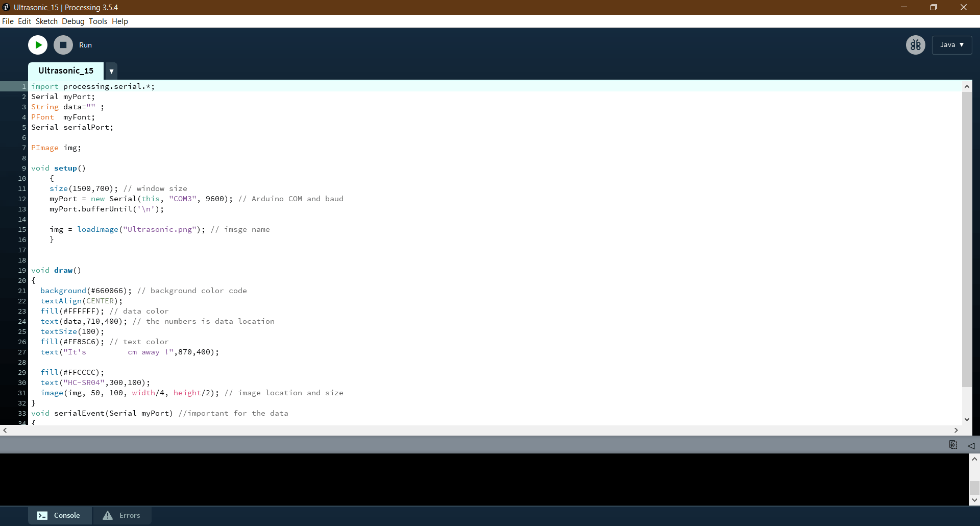
Processing Code
Serial myPort; listen to any serial communication, and for as to Arduino incoming data. String data="" ; is the data received from the serial port.
Just like Arduino has “setup()” and “loop()”, Processing has “setup()” and “draw()”.
setup() method, to set the serial port “COM” for which Arduino is connected, so Arduino and Processing are communicating at the same rate.
draw(), to take the data and display it, either in the black area at the bottom of the sketch, or in the window I chose for that. In this loop, I have specified the colors for the background and the size for the text, as well as the image.
Here I put several notes in the code, I know them by removing them and noting the comparison that occurs when viewing the result.
import processing.serial.*;
Serial myPort;
String data="" ;
PFont  myFont;
Serial serialPort;

PImage img;

void setup()
    {
    size(1500,700); // window size
    myPort = new Serial(this, "COM5", 9600); // Arduino COM and baud
    myPort.bufferUntil('\n');

    img = loadImage("Ultrasonic.png"); // imsge name
    }


void draw()
{
  background(#660066); // background color code
  textAlign(CENTER);
  fill(#FFFFFF); // data color
  text(data,710,400); // the numbers is data location
  textSize(100);
  fill(#FF85C6); // text color
  text("It's         cm away !",870,400);

  fill(#FFCCCC);
  text("HC-SR04",300,100);
  image(img, 50, 100, width/4, height/2); // image location and size
}
void serialEvent(Serial myPort) //important for the data
{
   data=myPort.readStringUntil('\n'); //important to display the data
}
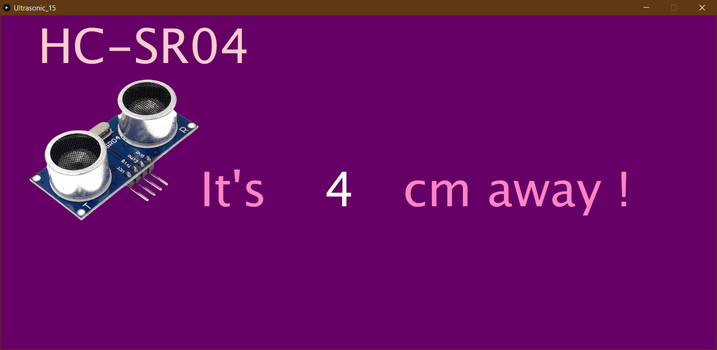
Click on the “Run” button, the circle in the top left of the screen to display the created window.
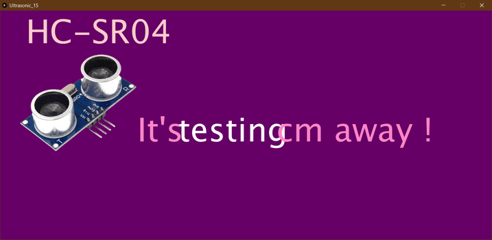
This is a screenshot of the window when displaying the readings.
This video shows the use of the ATtiny44 board to receive the ultrasonic readings and take them by the RX and TX to the Arduino that works as an ISP to deliver them to the Processing.
Problems
The same way I used it before, the result was on the serial monitor that only shows me question marks, I did “Burn Bootloader” but the same result.
After trying many times, finally, the result appeared in the serial monitor, which is the measurement of distance, as well as the word “testing” that I put to make sure the work of the serial monitor.

After the data appeared on the serial monitor, I moved to the processing program, but the result was that the data as well as the word “testing” appeared on the display window.
Files
Useful Links
- Processing Text Size
- Processing Importing Image
- Scaling an Image in Processing with Ultrasonic Sensor
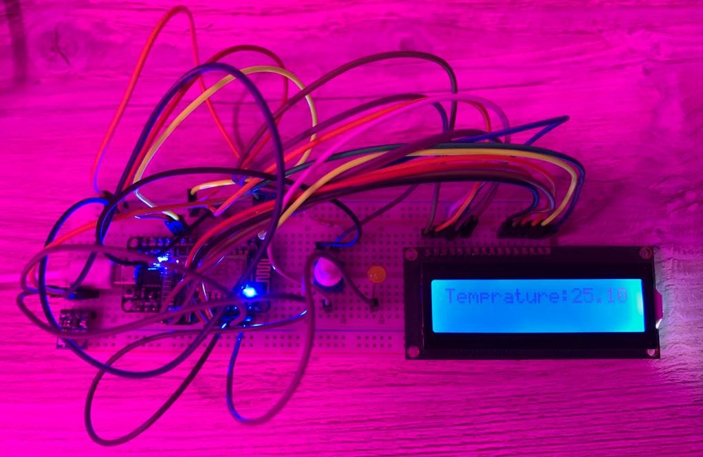
Liquid-crystal Display “LCD”
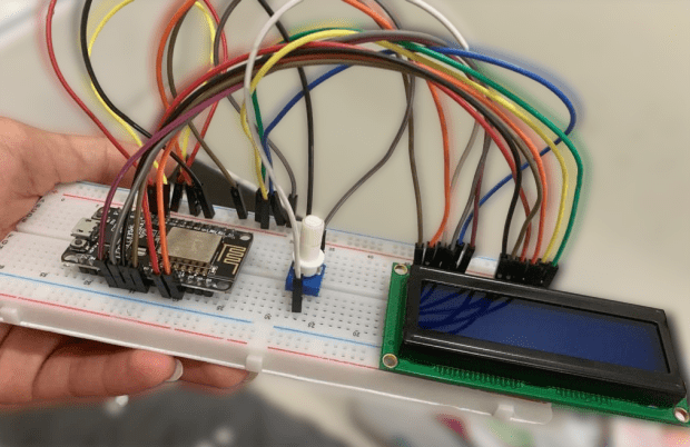
A Liquid Crystal Display is a display unit built using Liquid Crystal technology, and I used it to display text shows the temperature reading on the screen.
Connection
Source Code
I used this code to write my code. To see the code and the rest of the system details, open Networking and Communications week.
/*
 LiquidCrystal Library - Hello World


 Demonstrates the use a 16x2 LCD display. The LiquidCrystal
 library works with all LCD displays that are compatible with the
 Hitachi HD44780 driver. There are many of them out there, and you
 can usually tell them by the 16-pin interface.


 This sketch prints "Hello World!" to the LCD
 and shows the time.


 The circuit:
 * LCD RS pin to digital pin 12
 * LCD Enable pin to digital pin 11
 * LCD D4 pin to digital pin 5
 * LCD D5 pin to digital pin 4
 * LCD D6 pin to digital pin 3
 * LCD D7 pin to digital pin 2
 * LCD R/W pin to ground
 * LCD VSS pin to ground
 * LCD VCC pin to 5V
 * 10K resistor:
 * ends to +5V and ground
 * wiper to LCD VO pin (pin 3)


 Library originally added 18 Apr 2008
 by David A. Mellis
 library modified 5 Jul 2009
 by Limor Fried (http://www.ladyada.net)
 example added 9 Jul 2009
 by Tom Igoe
 modified 22 Nov 2010
 by Tom Igoe
 modified 7 Nov 2016
 by Arturo Guadalupi


 This example code is in the public domain.


 http://www.arduino.cc/en/Tutorial/LiquidCrystalHelloWorld


*/


// include the library code:
#include /search/%23include


// initialize the library by associating any needed LCD interface pin
// with the arduino pin number it is connected to
const int rs = D7, en = D8, d4 = D6 , d5 = D5, d6 = D4, d7 = D3;
LiquidCrystal lcd(rs, en, d4, d5, d6, d7);


void setup() {


 // set up the LCD's number of columns and rows:
 //lcd.begin(16, 2);
 // Print a message to the LCD.

}


void loop() {
 // set the cursor to column 0, line 1
 lcd.print("Good luck");
 delay(2000);
 lcd.clear();
 lcd.print("on the project");
  delay(2000);
 lcd.clear();
 delay(1000);


}
Result
This is the end result that will display the value of the temperature measured through BMP180 temperature sensor.