5. Electronics Production
Group assignment
To view the group assignment click here
Individual assignments
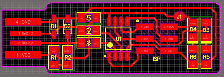
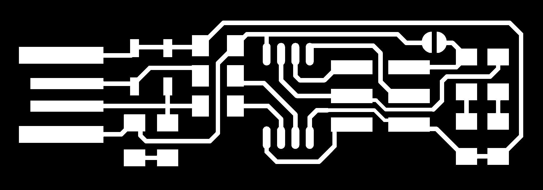
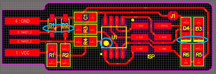
The required in this individual assignment is to make an in-circuit programmer by milling, stuffing, soldering and testing it. This is the Printed Circuit Board “PCB” I chose:
Milling
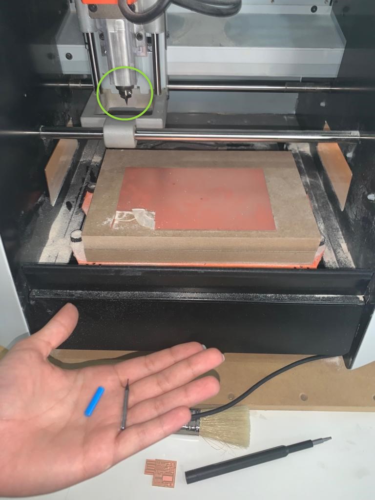
To mill the PCB we used a small milling machine “SRM-20”; It offers compact size and powerful functionality with no need for expert operating skills.

Prepare the Machine
- Fix the copper piece with a duct tape to ensure that the piece does not move while milling.
- Set the milling bits, 1/64 or 1/32 according to use.
Prepare the Milling
-
Download the PNG files for the traces and the board outline:
Traces (1000 dpi)
 Outline Cutout (1000 dpi)

-
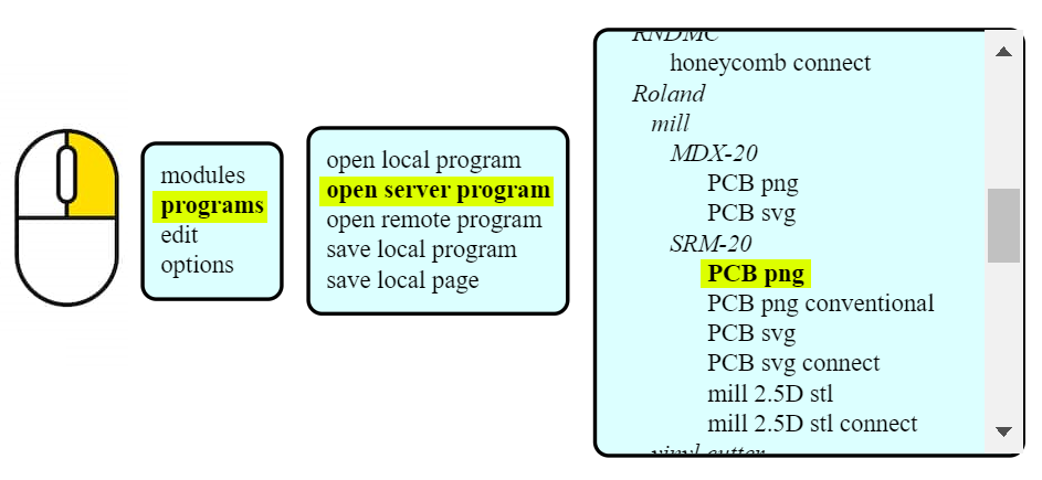
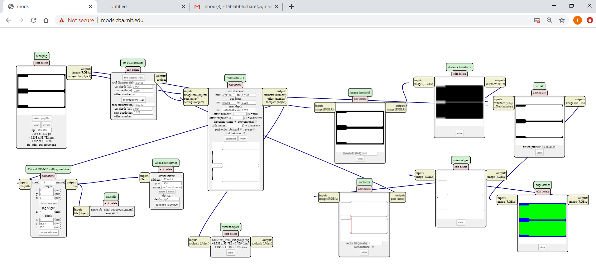
Open this website “http://mods.cba.mit.edu/”, “Right click” >> “program” >> “open server program” >> under “SRM-20” click on “PCB png”, We may also choose to use SVG files.
 And follow these steps:
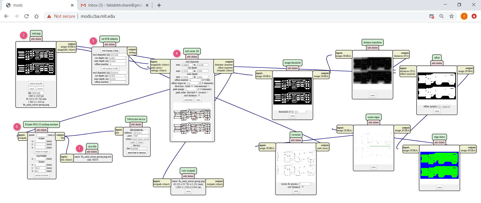
- “Right click” near “Roland SRM-20 milling machine”, “modules” » “open server module”, under “file” choose “save”. Match between the “outputs file” and the “inputs file(object)”.
- From “read png”, select your png file you want to mill. The machine understands that black color is what it mill it, and white is what it wil keep. Therefore, when we want to mill the outline board, we usually click on “invert” to switch the colors.
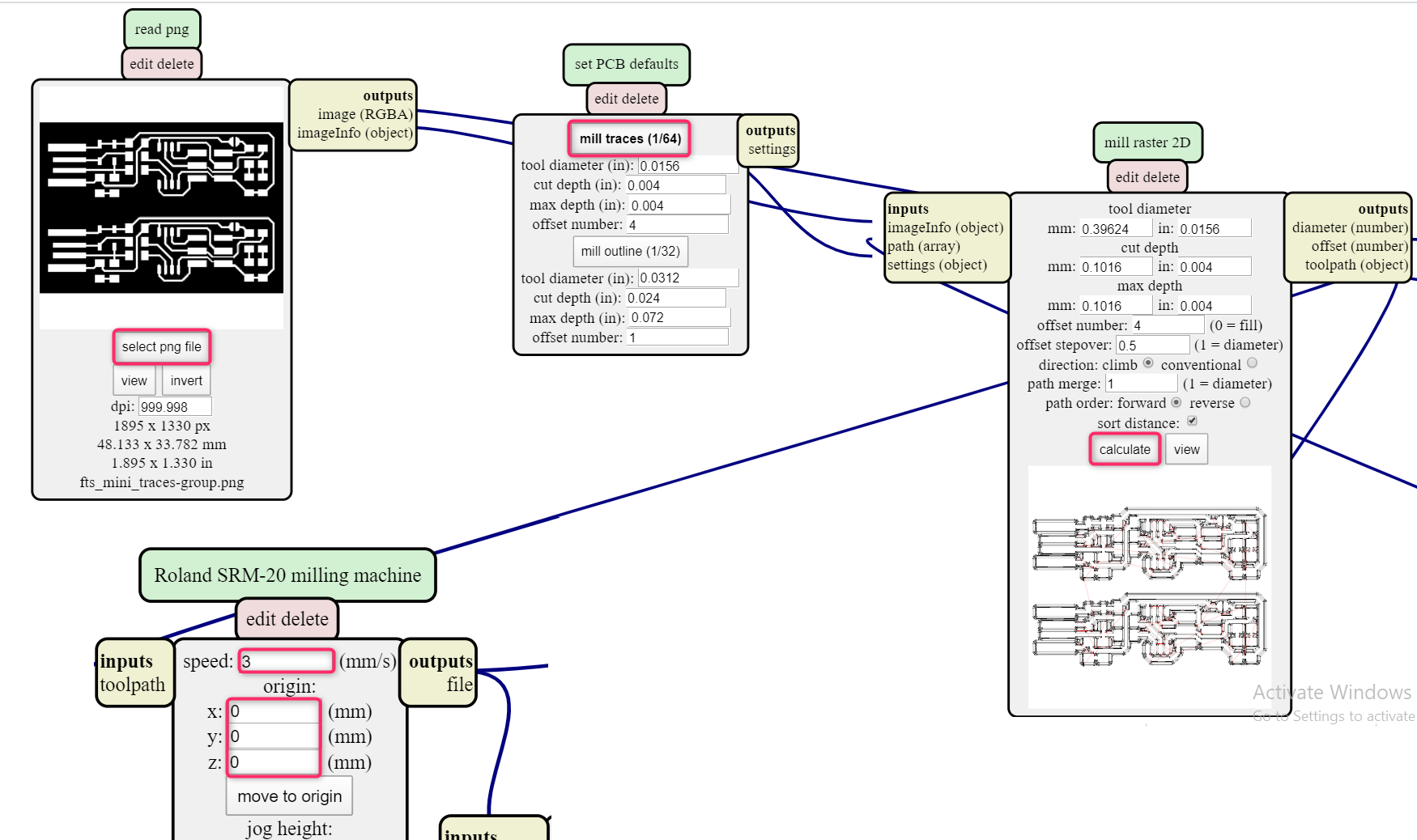
- From “set PCB defaults”, click on “mill traces (1/64)” for the inner design, if you want to mill border choose “mill outline (1/32)”.
- To download the .rml file, click on “calculate” from “mill raster 2D”. You can view your milling png, black lines are the direction of milling the copper while the red lines are the movement of the milling tool from one place to another.
- You can change the milling speed and the origin from “Roland SRM-20 milling machine”. Set the origin to zero, I once did not change the origin and they remained as they are on number “10” and the machine tried to mill on a height from the copper plate.
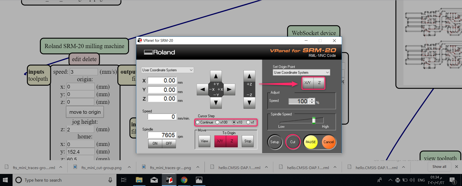
Prepare the Multi-axis milling From the Site to the Machine
1. Open “VPanel for SRM-20” and Set the X/Y axis by pressing the arrows first, “Cursor Step” can be used to control the movement speed of the milling tool, and it is not recommended to use a high speed when moving the Z axis. The origin is always the lower left.
2. Click on “cut” >> “delete all” to delete all the previous files >> “add” to add your .rml file >> “output” to start milling.
Note: If you want to mill again on the same X/Y or Z axis, click on “To Origin” “X/Y” or “Z”.
To mill the border* do the same stepss
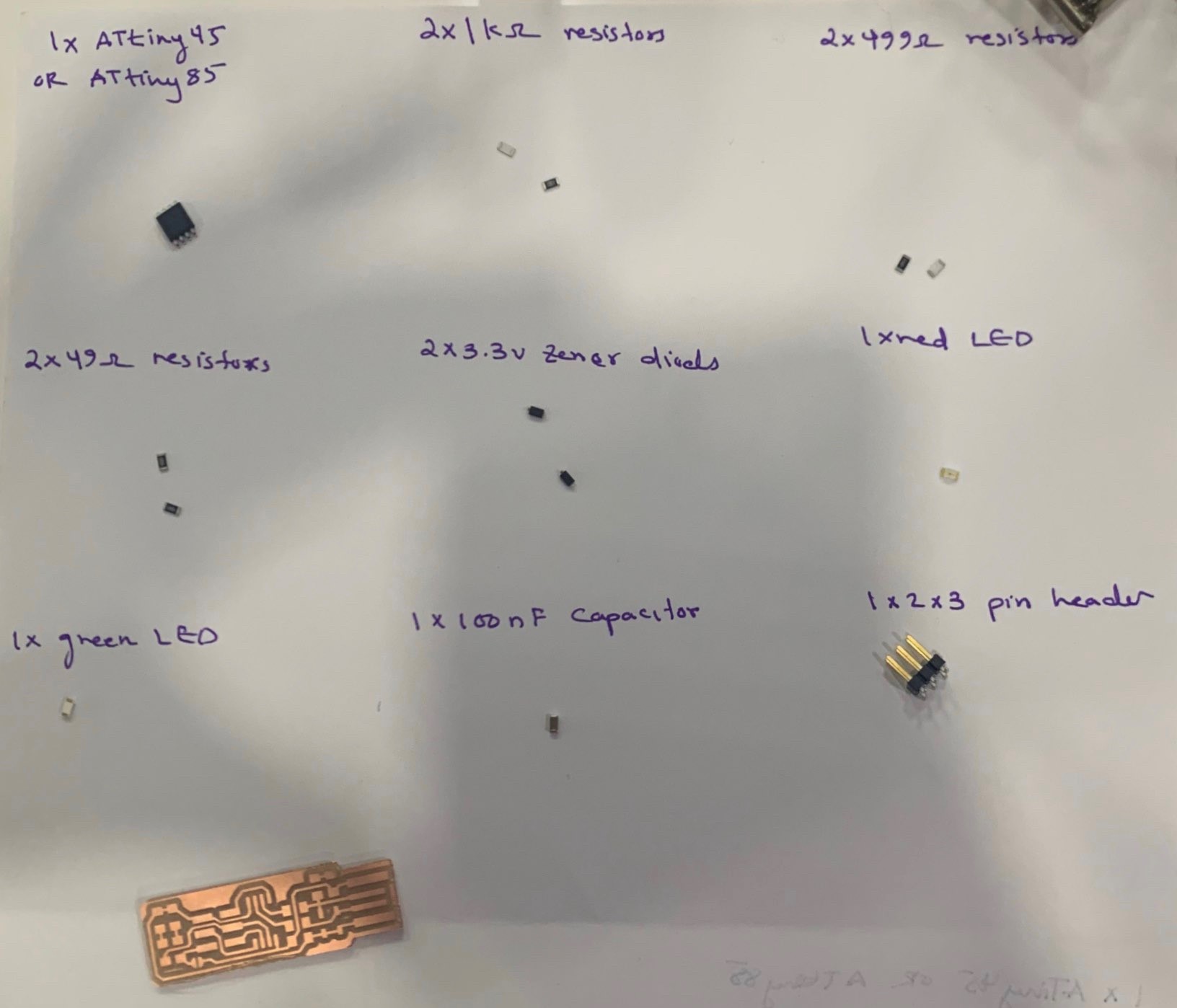
These are the components and the board ready for soldering:
Soldering
In the soldering process, the direction of the Atiny45, zener diodes and LED, should be observed.
With these tools I soldereed the component on the board:
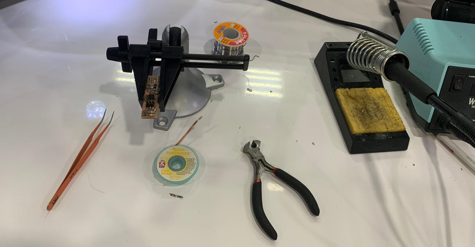
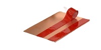
After I finished soldering, there were appendages of the molten which are difficult to remove with the soldering tool. I used a desoldering wick for that. Fine Braid “Super Wick” is a tightly woven, oxide-free copper braid coated with RMA flux. Its high purity and tight weave make it fast-wicking, quickly removing solder and minimizing dwell time.
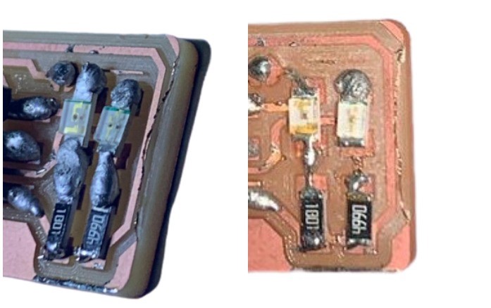
Place the desoldering wick directly on the excess material, then put the solder on it, so the excess material sticks to the wick. This is a picture of before and after using “SUPERWICK”.
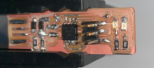
The Final Result:
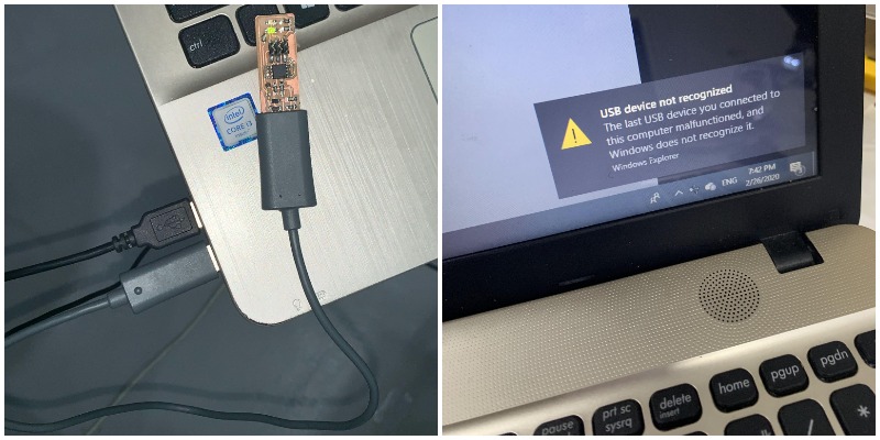
Testing
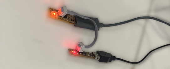
The “USB device not recognized” message when the programmer is first plugged into the computer does not mean that the device is functional, it just means that its detecting something connected to the PC.
I followed the same steps written on Building the FabTinyISP site.
- Download “Terminal” Program and open it.
- Enter the following command, followed by your password when prompted:
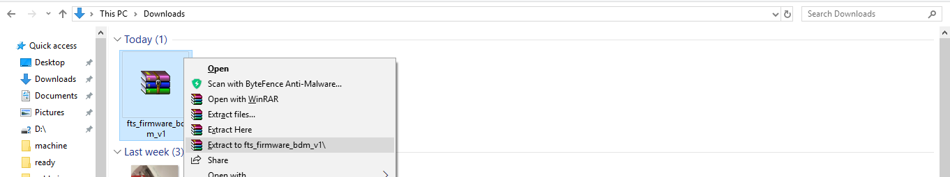
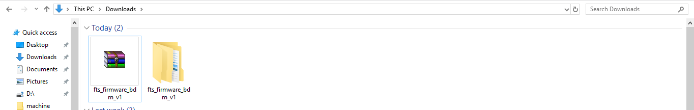
sudo apt install avrdude gcc-avr avr-libc make - Download the firmware source code and extract the zip file (on Linux, unzip fts_firmware_bdm_v1.zip).
- Run
make, to build the hex file that will get programmed onto the ATtiny45. - Figure out what avrdude (the programming software) calls it. For this ATtiny board
usbtiny. - Run the
make fusescommand. This will set up all of the fuses except the one that disables the reset pin.
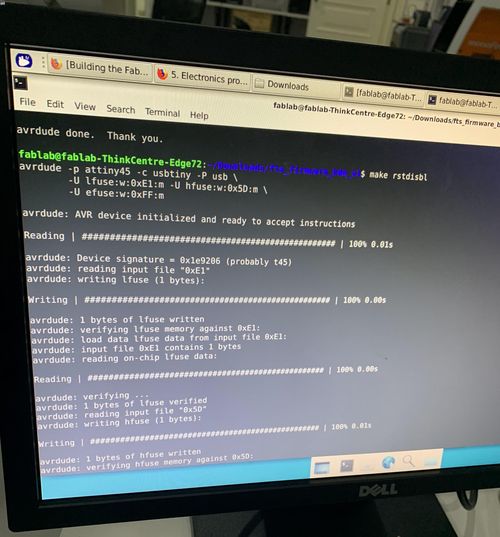
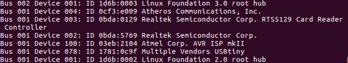
Here it shows that the laptop has recognized the programmer.